Chapter 12: Basic Diagrams and Systems
This page provides the chapter on basic fluid power diagrams and fluid power systems from the U.S. Navy's fluid power training course, NAVEDTRA 14105A, "Fluid Power," Naval Education and Training Professional Development and Technology Center, July 2015.
Other related chapters from the Navy's fluid power training course can be seen to the right.
Basic Diagrams and Systems
In the preceding chapters, you learned about hydraulic and pneumatic fluids and components of fluid power systems. While having knowledge of system components is essential, it is difficult to understand the interrelationships of these components by simply watching the system operate. The knowledge of system interrelation is required to effectively troubleshoot and maintain a fluid power system. Diagrams provided in applicable technical publications or drawings are a valuable aid in understanding the operation of the system and in diagnosing the causes of malfunctions.
This chapter explains the different types of diagrams used to illustrate fluid power circuits, including some of the symbols that depict fluid power components. Included in this chapter are descriptions and illustrations denoting the differences between open-center and closed-center fluid power systems. The last part of the chapter describes and illustrates some applications of basic fluid power systems.
Learning Objectives
When you have completed this chapter, you will be able to do the following:
- Recognize the importance of diagrams and symbols.
- Identify symbols used in diagrams.
- Identify the types of diagrams.
- Recognize Navy applications and component functions of hydraulic power drive systems.
- Recognize the construction features of hydraulic power drive systems.
- Recognize the operating characteristics of hydraulic power drive systems.
Diagrams
As mentioned in this chapter's introduction, to troubleshoot fluid power systems intelligently, a mechanic or technician must be familiar with the system on which he or she is working. The mechanic must know the function of each component in the system and have a mental picture of its location in relation to other components. The mental picture can be attained by studying the diagrams of the system.
A diagram may be defined as a graphic representation of an assembly or system that indicates the various parts and expresses the methods or principles of operations. The ability to read diagrams is a basic requirement for understanding the operation of fluid power systems. Understanding the diagrams of a system requires having knowledge of the symbols used in the schematic diagrams.
The standards and procedures prescribed for military drawings and blueprints are stated in military standards (MIL-STDs), military handbooks (MIL-HDBKs), American National Standards Institute (ANSI) standards, American Society of Mechanical Engineers (ASME), and the Institute of Electrical and Electronics Engineers (IEEE). The Acquisition Streamlining and Standardization Information System (ASSIST) Web site lists these standards. A list containing common standards, listed by number and title, that concern engineering drawings and blueprints are illustrated in Table 12-1.
| Number | Title |
|---|---|
| ASME Y14.100-2013 | Engineering Drawing Practices |
| ANSI Y14.5M-2009 | Dimensioning and Tolerancing |
| ANSI Y14.6-2001 | Screw Thread Representation |
| ASME B46.1-2009 | Surface Texture (Surface Roughness, Waviness, and Lay) |
| ASME Y14.38-2007 | Abbreviations and Acronyms for Use on Drawings and Related Documents |
| IEEE-315-1975 | Graphic Symbols for Electrical and Electronic Diagrams (Including Reference Designation Letters) |
| ANSI Y32.9 | Electrical Wiring Symbols for Architectural and Electrical Layout Drawings |
| ANSI Y32.16-1965 | Electrical and Electronic Reference Designations |
| ASTM F1000-13 | Standard Practice for Piping Systems Drawing Symbols |
| MIL-HDBK-21 | Welded-Joint Designs, Armored-Tank Type |
| MIL-STD-22D | Welded Joint Designs |
| MIL-STD-25B | Ship Structural Symbols for Use on Ship Drawings |
Symbols
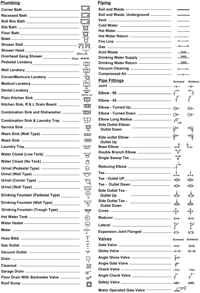
The American Society for Testing and Materials (ASTM) Standard F1000-13 lists mechanical symbols used on piping prints other than those for aeronautical, aerospacecraft, and spacecraft. Many of these symbols are also listed in the Organizational, Intermediate and Depot Maintenance Aviation Hydraulics Manual, Naval Air Systems Command (NAVAIR) 01-1A-17. A few of the common plumbing and piping symbols from the ASTM Standard F1000-13 and the Symbols, Piping Systems, Naval Sea Systems Command (NAVSEA) Standard Drawing 803-5001049 are illustrated in Figure 12-1.
Notice that the symbols may show the type of connections (screwed, flanged, welded, and so forth) including fittings, valves, gauges, and items of the equipment. When an item is not covered in the standards, the responsible activity designs a suitable symbol and provides an explanation in a note.
When a print shows more than one piping system of the same kind, additional letters are added to the symbols to differentiate between the systems. Notice the letters on the drinking water supply and drinking water return lines in Figure 12-1.
Some rules applicable to graphical symbols for fluid diagrams are as follows:
- Symbols show connections, flow paths, and the function of the component represented only. They do not indicate conditions occurring during transition from one flow path to another, nor do they indicate component construction or values, such as pressure or flow rate
- Symbols do not indicate the location of ports, direction of shifting of spools, or position of control elements on actual components
- Symbols may be rotated or reversed without altering their meaning except in cases of lines to reservoirs and vented manifolds
- Symbols may be drawn in any size
- Each symbol is drawn to show the normal or neutral condition of each component unless multiple circuit diagrams are furnished showing various phases of circuit operation
For more detailed information concerning the symbols used in fluid power diagrams, consult the above-mentioned military standards.
Color Coding for Safety
Color warnings mark physical hazards, indicate the location of safety equipment, and identify fire and other protective equipment.
The MIL-STD-101 establishes the color code used to identify piping carrying hazardous fluids. It applies to all piping installations in naval industrial plants and shore stations where color coding is used.
Five classes of materials have been selected to represent the general hazards for all dangerous materials, while a sixth class has been reserved for fire protection materials. A standard color represents each of these classes, as shown in Table 12-2. In some instances, piping systems that do not require warning colors may be painted to match surroundings; in other instances, such systems may be painted aluminum or black or remain unpainted.
| Class | Standard Color | Identification Marking | Class of Material |
|---|---|---|---|
| A | Yellow | FLAM | FLAMMABLE MATERIALS. All materials known ordinarily as flammables or combustibles. Of the chromatic colors, yellow has the highest coefficient of reflection under white light and can be recognized under the poorest conditions of illumination. |
| B | Brown | TOXIC | TOXIC AND POISONOUS MATERIALS. All materials extremely hazardous to life or health under normal conditions as toxics or poisons. |
| C | Blue | AAHM | ANESTHETICS AND HARMFUL MATERIALS. All materials productive of anesthetic vapors and all liquid chemicals and compounds hazardous to life and property but not normally productive of dangerous quantities of fumes or vapors. |
| D | Green | OXYM | OXIDIZING MATERIALS. All materials which readily furnish oxygen for combustion, and fire producers which react explosively or with the evolution of heat in contact with many other materials. |
| E | Gray | PHDAN | PHYSICALLY DANGEROUS MATERIALS. All materials not dangerous in themselves, but which are asphyxiating in confined areas or which are generally handled in a dangerous physical state of pressure or temperature. |
| F | Red | FPM | FIRE PROTECTION MATERIALS. Materials provided in piping systems or in compressed gas cylinders for use in fire protection. |
Types of Diagrams
There are many types of diagrams. Those that are most pertinent to fluid power systems are discussed in this section.
Pictorial Diagrams
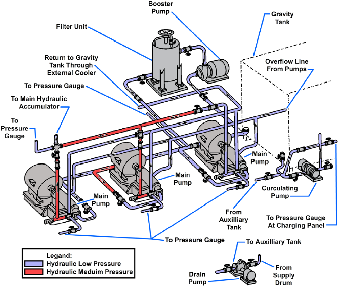
Pictorial diagrams (Figure 12-2) show the general location and actual appearance of each component, all interconnecting piping, and the general piping arrangement. This type of diagram is sometimes referred to as an installation diagram. Diagrams of this type are invaluable to maintenance personnel in identifying and locating components of a system.
Cutaway Diagrams
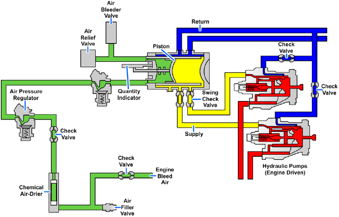
Cutaway diagrams (Figure 12-3) show the internal working parts of all fluid power components in a system. The diagrams include controls and actuating mechanisms and all interconnecting piping. Cutaway diagrams do not normally use symbols.
Graphic Diagrams
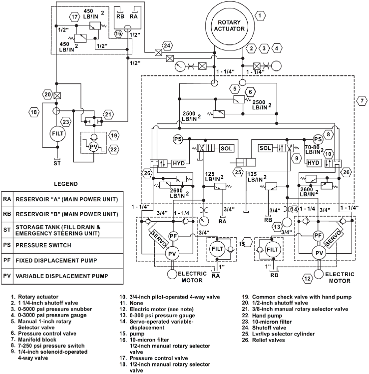
The primary purpose of a graphic (schematic) diagram is to enable the maintenance person to trace the flow of fluid from component to component within the system. This type of diagram uses standard symbols to show each component and includes all interconnecting piping. Additionally, the diagram contains a component list, pipe size, data on the sequence of operation, and other pertinent information. The graphic diagram (Figure 12-4) does not indicate the physical location of the various components, but it does show the relationship of each component to the other components within the system.
Fluid Power Systems
One type of system that is sometimes used in hydraulically operated equipment is the open-center system. An open-center system is one having fluid flow, but no pressure in the system when the actuating mechanisms are idle.
Another fluid power system used in hydraulically operated equipment is the closed-center system. In a closed-center system, the fluid in the system remains pressurized from the pump (or regulator) to the directional control valve while the pump is operating. In this type of system, any number of subsystems may be incorporated, with a separate directional control valve for each subsystem. The directional control valves are arranged in parallel so that system pressure acts equally on all control valves.
Open-Center System
In an open-center system, the pump circulates the fluid from the reservoir, through the selector valves, and back to the reservoir (Figure 12-5, view A). The open-center system may employ any number of subsystems, with a selector valve for each subsystem. Unlike the closed-center system, the selector valves of the open-center system are always connected in series with each other. In this arrangement, the system pressure line goes through each selector valve. Fluid is always allowed free passage through each selector valve and back to the reservoir until one of the selector valves is positioned to operate a mechanism.
When one of the selector valves is positioned to operate an actuating device, fluid is directed from the pump through one of the working lines to the actuator (Figure 12-5, view B). With the selector valve in this position, the flow of fluid through the valve to the reservoir is blocked. The pressure builds up in the system to overcome the resistance and moves the piston of the actuating cylinder. The fluid from the opposite end of the actuator returns to the selector valve and flows back to the reservoir. Operation of the system following actuation of the component depends on the type of selector valve being used.
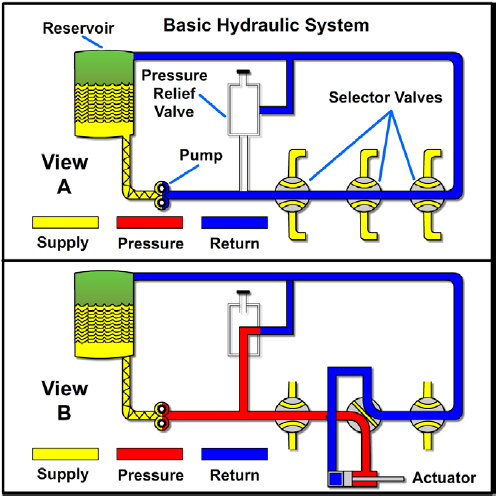
Several types of selector valves are used in conjunction with the open-center system. One type is both manually engaged and manually disengaged. First, the valve is manually moved to an operating position. Then, the actuating mechanism reaches the end of its operating cycle, and the pump output continues until the system relief valve relieves the pressure. The relief valve unseats and allows the fluid to flow back to the reservoir. The system pressure remains at the relief valve set pressure until the selector valve is manually returned to the neutral position. This action reopens the open-center flow and allows the system pressure to drop to line resistance pressure. The manually engaged and pressure disengaged type of selector valve is similar to the valve previously discussed. When the actuating mechanism reaches the end of its cycle, the pressure continues to rise to a predetermined pressure. The valve automatically returns to the neutral position and to open-center flow.
Closed-Center System
In the closed-center system, the fluid is under pressure whenever the power pump is operating. Figure 12-6 shows a complex closed-center system. The power pump may be one used with a separate pressure regulator control. The power pump may also be used with an integral pressure control valve that eliminates the need for a pressure regulator. This system differs from the open-center system in that the selector or directional control valves are arranged in parallel and not in series. The means of controlling pump pressure will vary in the closed-center system. If a constant delivery pump is used, the system pressure will be regulated by a pressure regulator. A relief valve acts as a backup safety device in case the regulator fails. If a variable displacement pump is used, system pressure is controlled by the pump's integral pressure mechanism compensator. The compensator automatically varies the volume output. When pressure approaches normal system pressure, the compensator begins to reduce the flow output of the pump. The pump is fully compensated (near zero flow) when normal system pressure is attained. When the pump is in this fully compensated condition, its internal bypass mechanism provides fluid circulation through the pump for cooling and lubrication. A relief valve is installed in the system as a safety backup.
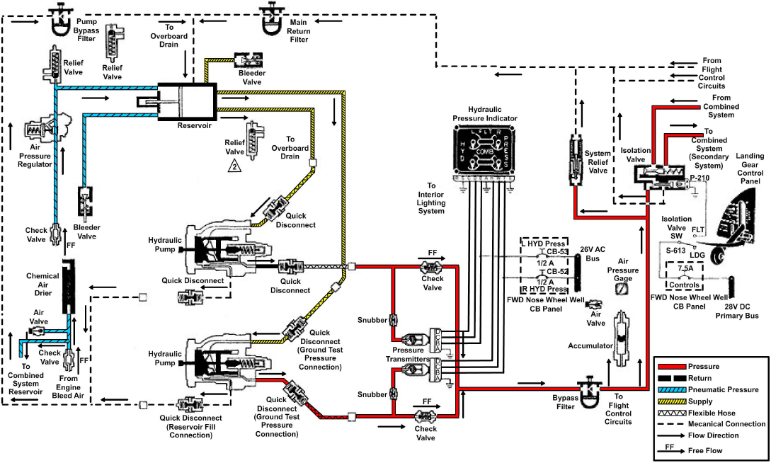
An advantage of the open-center system over the closed-center system is that the continuous pressurization of the system is eliminated. Since the pressure is built up gradually after the selector valve is moved to an operating position, there is very little shock from pressure surges. This action provides a smoother operation of the actuating mechanisms. However, the operation is slower than the closed-center system, in which the pressure is available the moment the selector valve is positioned. Since most aircraft applications require instantaneous operation, closed-center systems are the most widely used.
Hydraulic Power Drive System
The hydraulic power drive has been used in the Navy for many years. Proof of its effectiveness is that it has been used to train and elevate nearly all caliber guns, from the 40 mm gun mount to the 16-inch turret. In addition to gun mounts and turrets, hydraulic power drives are used to position rocket launchers and missile launchers, and to drive and control such equipment as windlasses, capstans, and winches.
In its simplest form, the hydraulic power drive consists of the following:
- The prime mover, which is the outside source of power used to drive the hydraulic pump
- A variable-displacement hydraulic pump
- A hydraulic motor
- A means of introducing a signal to the hydraulic pump to control its output
- Mechanical shafting and gearing that transmits the output of the hydraulic motor to the equipment being operated
Hydraulic power drives differ in some respects, such as size, method of control, and so forth. However, the fundamental operating principles are similar. The following paragraphs discuss the fundamental operating principles of a hydraulic power drive that is representative of those used to operate the 5-inch/54-caliber gun mount.
Figure 12-7 shows the basic components of the train power drive. The electric motor is constructed with drive shafts at both ends. The forward shaft drives the A-end pump through reduction gears, and the after shaft drives the auxiliary pumps through the auxiliary reduction gears. The reduction gears are installed because the pumps are designed to operate at a speed much slower than that of the motor.
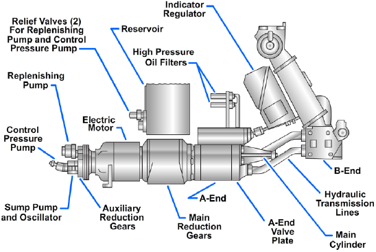
The replenishing pump is a spur gear pump. Its purpose is to replenish fluid to the active system of the power drive. It receives its supply of fluid from the reservoir and discharges it to the B-end valve plate. This discharge of fluid from the pump is held at a constant pressure by the action of a pressure relief valve. (Because the capacity of the pump exceeds replenishing demands, the relief valve is continuously allowing some of the fluid to flow back to the reservoir.)
The sump pump and oscillator unit has a twofold purpose. It pumps leakage, which collects in the sump of the indicator regulator, to the expansion tank. Additionally, it transmits a pulsating effect to the fluid in the response pressure system. Oscillations in the hydraulic response system help eliminate static friction of valves, allowing hydraulic control to respond faster.
The control pressure pump supplies high-pressure fluid for the hydraulic control system, brake pistons, lock piston, and the hand-controlled clutch operating piston. The control pressure pump is a fixed-displacement, axial piston type. An adjustable relief valve is used to limit the operating pressure at the outlet of the pump.
Control
For the purpose of this text, control constitutes the relationship between the stroke control shaft and the tilting box. The stroke control shaft is one of the piston rods of a double-acting piston-type actuating cylinder. This actuating cylinder and its direct means of control are referred to as the main cylinder assembly (Figure 12-8). It is the link between the hydraulic followup system and the power drive itself.

In hand control, the tilting box is mechanically positioned by gearing from the handwheel through the A-end control unit. In local and automatic control, the tilting box is positioned by the stroke control shaft. As shown in Figure 12-8, the extended end of the control shaft is connected to the tilting box. Movement of the shaft will pivot the tilting box one way or the other, which, in turn, controls the output of the A-end of the transmission. The other end of the shaft is attached to the main piston. A shorter shaft is attached to the opposite side of the piston. This shaft is also smaller in diameter. Thus, the working area of the left side of the piston is twice that of the area of the right side, as it appears in Figure 12-8.
Intermediate high-pressure (IHP) fluid is transmitted to the left side of the piston, while the high-pressure control (HPC) system fluid is transmitted to the right side. The HPC is held constant at 1,000 pounds per square inch (psi). Since the area of the piston upon which HPC acts is exactly one-half the area upon which IHP acts, the main piston is maintained in a fixed position when IHP is one-half HPC (500 psi). Whenever IHP varies from its normal value of 500 psi, the main piston will move, thus moving the tilting box.
Operation
Assume that a right train order signal is received. This signal will cause the pilot valve to be pulled upward. The fluid in the upper chamber of the amplifier piston can now flow through the lower land chamber of the fine pilot to exhaust. The fluid will cause the amplifier piston to move upward, and the fluid in the right-hand chamber of the main control valve can flow into the lower chamber of the amplifier valve.
The main control valve will now move to the right, IHP will drop below 500 psi, and the stroke piston will move to the left. Movement of the stroke piston will cause tilt to be put on the tilt plate, and the A-end will cause the mount to train right.
Figure 12-9 is a simplified block diagram showing the main element of the hydraulic power drive system under automatic control for clockwise and counterclockwise rotation.
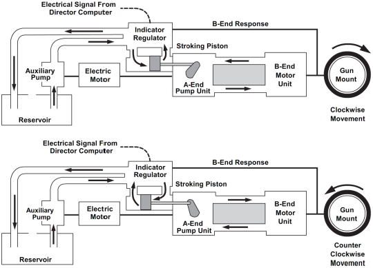
There are two principal problems in positioning a gun to fire. One is to get an accurate gun-order signal. This problem is solved by the director-computer combination. The other problem is to transmit the director signal promptly to the gun so that the position and movements of the gun will be synchronized with the signals from the director.
The problem of transforming gun-order signals to mount movements is solved by the power drive and its control — the indicator regulator. The indicator regulator controls the power drive, which controls the movement of the gun.
The indicator regulator receives an initial electrical gun-order from the director-computer, compares it to the existing mount position, and sends an error signal to the hydraulic control mechanism in the regulator. The hydraulic control mechanism controls the flow to the stroke control shaft, which positions the tilting box in the A-end of the transmission. Its tilt controls the volume and direction of fluid pumped to the B-end and, therefore, the speed and direction of the drive shaft of the B-end. Through mechanical linkage, the B-end output shaft moves the gun in the direction determined by the signal. At the same time, B-end response is transmitted to the indicator regulator and is continuously combined with incoming gun-order signals to give the error between the two. This error is modified hydraulically, according to the system of mechanical linkages and valves in the regulator. When the gun is lagging behind the signal, its movement is accelerated; and when it begins to catch up, its movement is slowed down so that it will not overrun excessively.
Landing Gear Emergency System
If the landing gear fails to extend to the down and locked position, each naval aircraft has an emergency method to extend the landing gear. Emergency extension systems may vary from one aircraft to another. The methods used may be the auxiliary/emergency hydraulic system, the air or nitrogen system, or the mechanical free-fall system. An aircraft may contain a combination of these systems. For example, the main landing gear and the nose gear emergency extension may be operated by the auxiliary/hydraulic system method.
The nitrogen storage bottle system is a one-shot system powered by nitrogen pressure stored in compressed nitrogen bottles (Figure 12-10). When the EMER LG PULL handle is disengaged from the LDG GEAR handle and moved aft to EMER DOWN, a crank linked to the handle is raised. The raised crank pulls an actuating cable that operates a lever, opening the spring-loaded emergency release valve. When the release valve opens, nitrogen pressure goes from the CYL port to shuttle valves on the nose gear, main gear, main gear door, and tail skid actuating cylinders. Pressure also goes to the landing gear and tail skid dump valves.
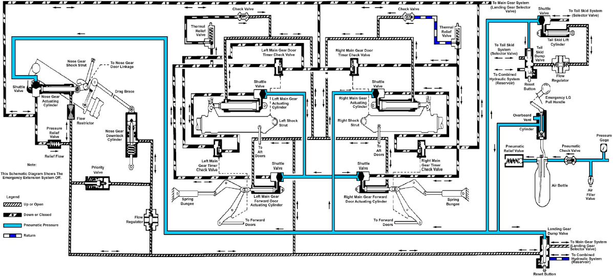
Pneumatic pressure actuates the dump valves to the emergency position. The valves are held in position by a spring-loaded detent. In this position, the uplines between the dump valves and the respective selector valves are blocked off. All landing gear and tail skid system uplines are ported to the combined system reservoir through the respective dump valves. (With the selector valves bypassed, a malfunction in either selector valve cannot prevent emergency extension.) Hydraulic fluid on the up side of each actuating cylinder flows back to the reservoir and allows pneumatic pressure to enter the down side and extend the gear and the tail skid.
Pneumatic pressure applied to each shuttle valve shifts a spool over to block off the hydraulic port. Pressure enters the down port and extends the actuating cylinder, displacing hydraulic fluid on the up side back to the reservoir through the landing gear or tail skid dump valve. (The main gear doors and the main gear shock struts begin to lower at the same time since the hydraulic door timer check valves are bypassed during pneumatic operation; however, the doors open fast enough to clear the shock struts since the door cylinders have approximately one-half the stroke of the gear actuating cylinders.)
Once the emergency extension system has been used, the system must be reset before the gear and tail skid can be extended again by either normal or emergency means. With the aircraft on jacks, the EMER LG PULL handle is moved from EMER DOWN and is engaged with the LDG GEAR handle. This seats the emergency release valve and opens the pneumatic extension lines to the atmosphere through the OVBD port of the release valve. Most of the pressurized nitrogen in the lines then flows back through the emergency release valve and is discharged overboard. The reset buttons on the dump valves are then manually pressed, resetting the dump valves to their normal position. In the normal position, the selector valves are connected to the landing gear and tail skid lines.
Jet Blast Deflectors
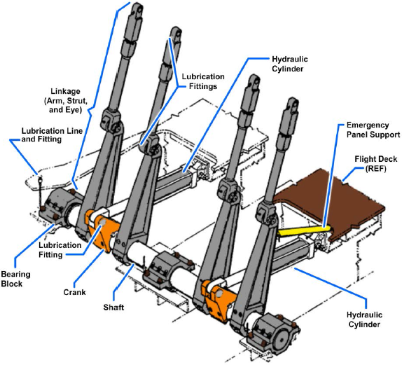
Jet blast deflectors (JBDs) onboard aircraft carriers are raised and lowered by hydraulic cylinders through mechanical linkage. Two hydraulic cylinders are attached to each JBD panel shaft by crank assemblies (Figure 12-11). The shaft is rotated by the push and pull operation of the hydraulic cylinders. Shaft rotation extends or retracts the linkage to raise or lower the JBD panels. This operation is designed so that in the event of a failure of one of the hydraulic cylinders, the other one will raise or lower the panels.
Hydraulic fluid from the catapult hydraulic supply system is supplied to the JBD hydraulic system through an isolation valve and a filter to the four-way control valve (stack valve) assembly (Figure 12-12).
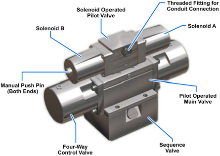
The four-way control valve assembly consists of the following:
- Pilot-operated pilot valve — small valve that controls a limited flow of fluid and is often used in critical applications such as emergency or safety controls
- Solenoid-operated pilot valve — electromechanically operated valve controlled by an electrical current (110 volts) through a solenoid
- Sequence valve — used to control the sequence of two or more hydraulic actuators
All three valves are secured together to conserve space and simplify connection to a subplate or manifold as shown in Figure 12-12. One stack valve controls fluid flow for a pair of panel assemblies. Three stack valves are required for Mk 7 Mod 0/2 and two stack valves for Mk 7 Mod 1 JBDs. Hydraulic fluid at 2,500 psi from the associated catapult is supplied to the stack valve, with all fluid return lines going to that catapult gravity tank.
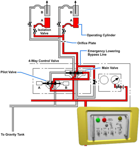
With hydraulic fluid at normal operating pressure and neither solenoid B (raise) nor solenoid A (lower) energized, fluid flows through the sequence valve and pilot valve to both sides of the slide in the main valve. This pressure to both sides of the slide keeps it centered and blocks fluid flow into and out of both ends of the hydraulic cylinders.
Electrical shock can cause injury or death. Verify that power is off by using an electrical power indicator device such as a voltmeter prior to performing any work.
JBD Raising Operation
When a raise switch is actuated (Figure 12-13), solenoid B in the pilot valve energizes, shifting the spool and directing pressure to a pilot port at the main valve slide. The slide shifts and directs fluid to port A of both hydraulic cylinders. The hydraulic cylinder pistons extend, pushing the crank assembly of the operating gear aft and rotating the shaft. Rotation of the shaft extends the operating gear linkage and raises the associated panel assemblies. During the raise cycle, fluid in the cylinder lower port B vents to the gravity tank through the main valve. If the raise switch is released during the raise cycle, solenoid B de-energizes, a spring returns the solenoid spool to the centered position, and panel movement will stop.
Switches on the control panel, auxiliary panel, and portable panel assembly (chest pack) are momentary-contact "dead man" switches. They must be pressed until the panels are fully raised or fully lowered.
JBD Lowering Operation
When a lower switch is actuated (Figure 12-14), solenoid A in the pilot valve energizes, shifting the spool and directing pressure to a pilot port at the main valve slide. The slide shifts in the opposite direction (from rising) and directs fluid to port B of both hydraulic cylinders. The pistons retract, pulling the crank assembly of the operating gear forward and rotating the shaft. The rotation of the shaft retracts the operating gear linkage and lowers the panels. During the lower cycle, fluid in the raise port A vents to the gravity tank through the main valve. If the lower switch is released during the lower cycle, solenoid A de-energizes, a spring returns the solenoid spool to the centered position, and panel movement will stop.
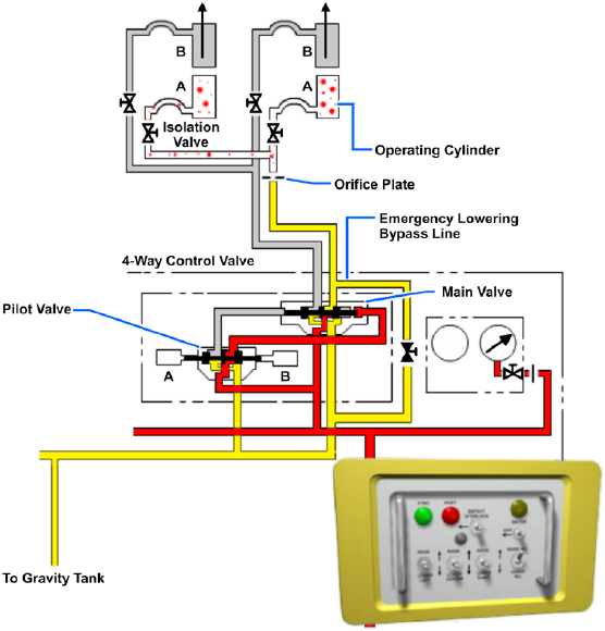
Momentary contact switches light up in the down and up positions. With the JBD panels down, the DOWN light switches are GREEN. When the panels are raised, the green lights go out, and when fully raised the UP light switches turn AMBER. When the panels are lowered, the UP light switches' amber lights go out, and when fully down the DOWN light switches turn green.
PDH Classroom offers a continuing education course based on this basic diagrams and systems reference page. This course can be used to fulfill PDH credit requirements for maintaining your PE license.
Now that you've read this reference page, earn credit for it!
