Chapter 2: Forces in Liquids
This page provides the chapter on forces in liquids from the U.S. Navy's fluid power training course, NAVEDTRA 14105A, "Fluid Power," Naval Education and Training Professional Development and Technology Center, July 2015.
Other related chapters from the Navy's fluid power training course can be seen to the right.
Forces in Liquids
The study of liquids is divided into two main parts: liquids at rest (hydrostatics) and liquids in motion (hydraulics).
The effects of liquids at rest can often be expressed by simple formulas. The effects of liquids in motion are more difficult to express due to frictional and other factors whose actions cannot be expressed by simple mathematics.
In chapter 1 we learned that liquids have a definite volume but take the shape of their containing vessel. There are two additional characteristics we must explore prior to proceeding.
Liquids are almost incompressible. For example, if a pressure of 100 pounds per square inch (psi) is applied to a given volume of water that is at atmospheric pressure, the volume will decrease by only 0.03 percent. It would take a force of approximately 32 tons to reduce its volume by 10 percent; however, when this force is removed, the water immediately returns to its original volume. Other liquids behave in about the same manner as water.
Another characteristic of a liquid is the tendency to keep its free surface level. If the surface is not level, liquids will flow in the direction that will tend to make the surface level.
Learning Objectives
When you have completed this chapter, you will be able to do the following:
- Recognize the pressure characteristics of liquids.
- Describe how pressure is caused by the weight of the atmosphere.
- Explain how pressures are measured.
- Identify terms and facts applicable to the physics of fluids.
- Solve problems pertaining to density and specific gravity.
- Recognize the principles and equations involved with the transmission of forces.
- Solve problems and equations involved with the transmission of forces.
- Recognize the characteristics and behavior of fluids in motion.
- Explain the methods for measuring volume and velocity.
- Relate the dynamic and static factors involved with fluid flow.
- Describe the operating characteristics and component functions of basic fluid power systems.
Liquids at Rest
In studying fluids at rest, we are concerned with the transmission of force and the factors that affect the forces in liquids. Additionally, pressure in and on liquids and factors affecting pressure are of great importance.
Pressure and Force
The terms force and pressure are used extensively in the study of fluid power. It is essential that we distinguish between the terms. Force means a total push or pull. It is the push or pull exerted against the total area of a particular surface and is expressed in pounds or grams. Pressure means the amount of push or pull (force) applied to each unit area of the surface and is expressed in pounds per square inch (lb/in2) or grams per square centimeter (g/cm2). Pressure may be exerted in one direction, in several directions, or in all directions.
Computing Force, Pressure, and Area
A formula is used in computing force, pressure, and area in fluid power systems. In these formulas, P refers to pressure, F indicates force, and A represents area.
Force equals pressure times area. Thus, the formula is written:
Pressure equals force divided by area. By rearranging the formula, this statement may be condensed into:
Since area equals force divided by pressure, the formula is written:
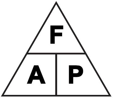
A memory device for recalling the different variations of this formula is shown in Figure 2-1. Any letter in the triangle may be expressed as the product or quotient of the other two, depending on its position within the triangle.
To determine the area, use the formula for finding the area of a circle. This is written A = π r2 where A is the area, 3.1416 (3.14 or 3 1/7 for most calculations), and r2 indicates the radius squared.
Sometimes the area may not be expressed in square units. If the surface is rectangular, you can determine its area by multiplying its length (say, in inches) by its width (also in inches). The majority of areas you will consider in these calculations are circular in shape. Either the radius or the diameter may be given, but you must know the radius in inches to find the area. The radius is one-half the diameter.
Atmospheric Pressure
The atmosphere is the entire mass of air that surrounds the earth. While it extends upward for about 500 miles, the section of primary interest is the portion that rests on the earth's surface and extends upward for about 7 1/2 miles. This layer is called the troposphere.
If a column of air 1-inch square extending all the way to the "top" of the atmosphere could be weighed, this column of air would weigh approximately 14.7 pounds at sea level. Thus, atmospheric pressure at sea level is approximately 14.7 psi.
As one ascends, the atmospheric pressure decreases by approximately 1.0 psi for every 2,343 feet. However, below sea level, in excavations and depressions, atmospheric pressure increases. Pressures under water differ from those under air only because the weight of the water must be added to the pressure of the air.
Atmospheric pressure can be measured by any of several methods. The common laboratory method uses the mercury column barometer. The height of the mercury column serves as an indicator of atmospheric pressure. At sea level and at a temperature of 0 degrees Celsius (°C), the height of the mercury column is approximately 30 inches, or 76 centimeters. This represents a pressure of approximately 14.7 psi. The 30-inch column is used as a reference standard.
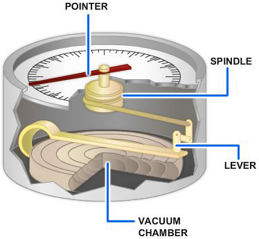
Another device used to measure atmospheric pressure is the aneroid barometer. The aneroid barometer uses the change in shape of an evacuated metal cell to measure variations in atmospheric pressure (Figure 2-2). The thin metal of the aneroid cell moves in or out with the variation of pressure on its external surface. This movement is transmitted through a system of levers to a pointer, which indicates the pressure.
The atmospheric pressure does not vary uniformly with altitude. It changes more rapidly at lower altitudes because of the compressibility of the air, which causes the air layers close to the earth's surface to be compressed by the air masses above them. This effect, however, is partially counteracted by the contraction of the upper layers due to cooling. The cooling tends to increase the density of the air.
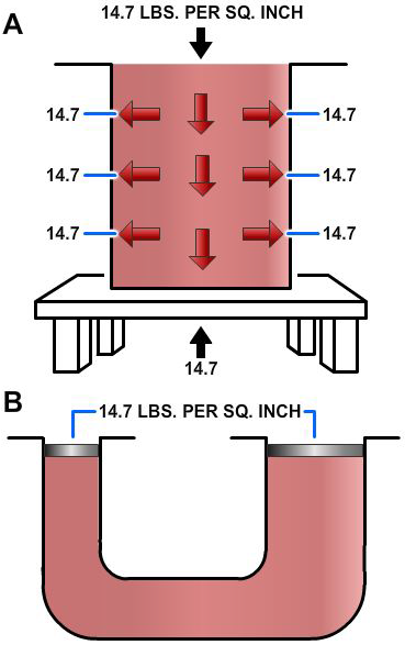
Atmospheric pressures are quite large, but in most instances practically the same pressure is present on all sides of objects so that no single surface is subjected to a great load.
Atmospheric pressure acting on the surface of a liquid (Figure 2-3, view A) is transmitted equally throughout the liquid to the walls of the container, but is balanced by the same atmospheric pressure acting on the outer walls of the container. Atmospheric pressure acting on the surface of one piston is balanced (Figure 2-3, view B) by the same pressure acting on the surface of the other piston. The different areas of the two surfaces make no difference, since for a unit of area, pressures are balanced.
Transmission of Forces Through Liquids
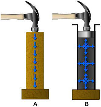
When the end of a solid bar is struck, the main force of the blow is carried straight through the bar to the other end (Figure 2-4, view A). This happens because the bar is rigid. The direction of the blow almost entirely determines the direction of the transmitted force. The more rigid the bar, the less force is lost inside the bar or transmitted outward at right angles to the direction of the blow.
When a force is applied to the end of a column of confined liquid (Figure 2-4, view B), it is transmitted straight through to the other end and also equally and undiminished in every direction throughout the column — forward, backward, and sideways — so that the containing vessel is literally filled with pressure.
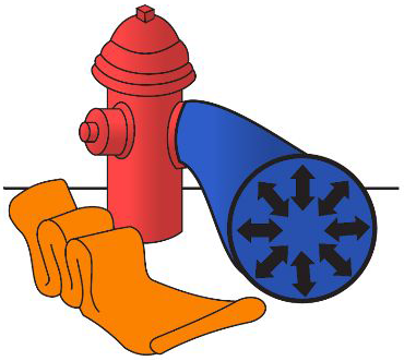
An example of this distribution of force is illustrated in Figure 2-5. The flat hose takes on a circular cross section when it is filled with water under pressure. The outward push of the water is equal in every direction.
So far we have explained the effects of atmospheric pressure on liquids and how external forces are distributed through liquids. Let us now focus our attention on forces generated by the weight of liquids themselves. To do this, we must first discuss density, specific gravity, and Pascal's law.
Density and Specific Gravity
The density of a substance is its weight per unit volume. The unit volume in the English system of measurement is 1 cubic foot. In the metric system it is the cubic centimeter; therefore, density is expressed in pounds per cubic foot or in grams per cubic centimeter.
To find the density (D) of a substance, you must know its weight (W) and volume (V). You then divide its weight by its volume to find the weight per unit volume. In equation form, this is written as:
EXAMPLE: The liquid that fills a certain container weighs 1,497.6 pounds. The container is 4 feet long, 3 feet wide, and 2 feet deep. Its volume is 24 cubic feet (4 ft x 3 ft x 2 ft). If 24 cubic feet of this liquid weighs 1,497.6 pounds, then 1 cubic foot weighs 62.4.
Therefore, the density of the liquid is 62.4 pounds per cubic foot.
This is the density of water at 4 °C and is usually used as the standard for comparing densities of other substances. The temperature of 4 °C was selected because water has its maximum density at this temperature. In the metric system, the density of water is 1 gram per cubic centimeter. The standard temperature of 4 °C is used whenever the density of liquids and solids is measured. Changes in temperature will not change the weight of a substance but will change the volume of the substance by expansion or contraction, thus changing the weight per unit volume.
In physics, the word specific implies a ratio. Weight is the measure of the earth's attraction for a body. The earth's attraction for a body is called gravity. Thus, the ratio of the weight of a unit volume of some substance to the weight of an equal volume of a standard substance, measured under standard pressure and temperature conditions, is called specific gravity. The terms specific weight and specific density are sometimes used to express this ratio.
The following formulas are used to find the specific gravity (sp gr) of solids and liquids, with water used as the standard substance.
$$ \text{sp gr} = { \text{Weight of the substance} \over \text{Weight of an equal volume of water} } $$or,
$$ \text{sp gr} = { \text{Density of the substance} \over \text{Density of water} } $$The same formulas are used to find the specific gravity of gases by substituting air, oxygen, or hydrogen for water.
The specific gravity of water is 1 (62.4 / 62.4).
If a cubic foot of a certain liquid weighs 68.64 pounds, then its specific gravity is 1.1, (68.64 / 62.4).
Thus, the specific gravity of the liquid is the ratio of its density to the density of water. If the specific gravity of a liquid or solid is known, the density of the liquid or solid may be obtained by multiplying its specific gravity by the density of water. For example, if a certain hydraulic liquid has a specific gravity of 0.8, 1 cubic foot of the liquid weighs 0.8 times as much as a cubic foot of water — 0.8 times 62.4, or 49.92 pounds. In the metric system, 1 cubic centimeter of a substance with a specific gravity of 0.8 weighs 1 times 0.8, or 0.8 grams. (Note that in the metric system the specific gravity of a liquid or solid has the same numerical value as its density, because water weighs 1 gram per cubic centimeter.)
Specific gravity and density are independent of the size of the sample under consideration and depend only on the substance of which it is made.
A device called a hydrometer is used for measuring the specific gravity of liquids.
Pascal's Law
Recall from chapter 1 that the foundation of modern hydraulics was established when Pascal discovered that pressure in a fluid acts equally in all directions. This pressure acts at right angles to the containing surfaces. If some type of pressure gauge, with an exposed face, is placed beneath the surface of a liquid (Figure 2-6) at a specific depth and pointed in different directions, the pressure will read the same. Thus, we can say that pressure in a liquid is independent of direction.
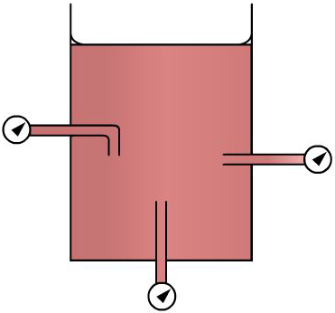
Pressure due to the weight of a liquid, at any level, depends on the depth of the fluid from the surface. If the exposed face of the pressure gauges (Figure 2-6) is moved closer to the surface of the liquid, the indicated pressure will be less. When the depth is doubled, the indicated pressure is doubled. Thus the pressure in a liquid is directly proportional to the depth.
Consider a container with vertical sides (Figure 2-7) that is 1 foot long and 1 foot wide. Let it be filled with water 1 foot deep, providing 1 cubic foot of water. We learned earlier in this chapter that 1 cubic foot of water weighs 62.4 pounds. Using this information and equation 2-2, P = F/A, we can calculate the pressure on the bottom of the container.
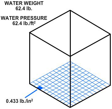
P = F / A
= 62.4 lbs / 1 ft2
= 62.4 lb/ft2
Since there are 144 square inches in 1 square foot,
P(psi) = 62.4 lbs / 144 in2 = 0.433 psi
This equation can be stated as follows: the weight of a column of water 1 foot high, having a cross-sectional area of 1 square inch, is 0.433 pound.
If the depth of the column is tripled, the weight of the column will be 3 x 0.433, or 1.299 pounds, and the pressure at the bottom will be 1.299 (psi), since pressure equals the force divided by the area. Thus, the pressure at any depth in a liquid is equal to the weight of the column of liquid at that depth divided by the cross-sectional area of the column at that depth. The volume of a liquid that produces the pressure is referred to as the fluid head of the liquid. The pressure of a liquid due to its fluid head is also dependent on the density of the liquid.
If we let A equal any cross-sectional area of a liquid column and h equal the depth of the column, the volume becomes Ah. Using equation 2-4, D = W/V, the weight of the liquid above area A is equal to AhD.
Since pressure is equal to the force per unit area, set A equal to 1. Then the formula pressure becomes
It is essential that h and D be expressed in similar units. That is, if D is expressed in pounds per cubic foot, the value of h must be expressed in feet. If the desired pressure is to be expressed in pounds per square inch, the pressure formula, equation 2-5, becomes
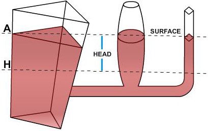
Pascal was also the first to prove by experiment that the shape and volume of a container in no way alters pressure. Thus in Figure 2-8, if the pressure due to the weight of the liquid at a point on horizontal line H is 8 psi, the pressure is 8 psi everywhere at level H in the system. Equation 2-5 also shows that the pressure is independent of the shape and volume of a container.
Pressure and Force in Fluid Power Systems
Recall that, according to Pascal's law, any force applied to a confined fluid is transmitted in all directions throughout the fluid regardless of the shape of the container. Consider the effect of this in the system shown in Figure 2-9. If there is a resistance on the output piston and the input piston is pushed downward, a pressure is created through the fluid, which acts equally at right angles to surfaces in all parts of the container.
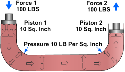
If force 1 is 100 pounds and the area of the input piston is 10 square inches, then the pressure in the fluid is 10 psi:
Fluid pressure cannot be created without resistance to flow. In this case, resistance is provided by the equipment to which the output piston is attached. The force of resistance acts against the top of the output piston. The pressure created in the system by the input piston pushes on the underside of the output piston with a force of 10 pounds on each square inch.
In this case, the fluid column has a uniform cross section, so the area of the output piston is the same as the area of the input piston, or 10 square inches. Therefore, the upward force on the output piston is 100 pounds (10 psi x 10 in2), the same as the force applied to the input piston. All that was accomplished in this system was to transmit the 100-pound force around the bend. However, this principle underlies practically all mechanical applications of fluid power.
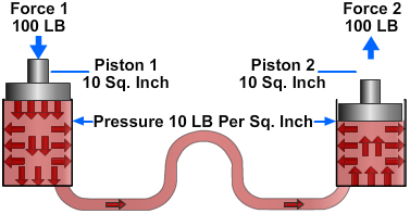
At this point you should note that since Pascal's law is independent of the shape of the container, it is not necessary that the tube connecting the two pistons have the same cross-sectional area of the pistons. A connection of any size, shape, or length will do, as long as an unobstructed passage is provided. Therefore, the system shown in Figure 2-10, with a relatively small, bent pipe connecting two cylinders, will act exactly the same as the system shown in Figure 2-9.
Multiplication of Forces
Consider the situation in Figure 2-11, where the input piston is much smaller than the output piston. Assume that the area of the input piston is 2 square inches. With a resistant force on the output piston, a downward force of 20 pounds acting on the input piston creates a pressure of 10 psi in the fluid. Although this force is much smaller than the force applied in Figures 2-9 and 2-10, the pressure is the same. This is because the force is applied to a smaller area.
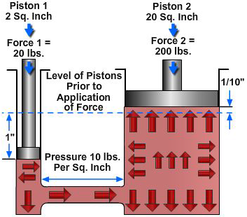
This pressure of 10 psi acts on all parts of the fluid container, including the bottom of the output piston. The upward force on the output piston is 200 pounds (10 pounds of pressure on each square inch). In this case, the original force has been multiplied tenfold while using the same pressure in the fluid as before. In any system with these dimensions, the ratio of output force to input force is always 10 to 1, regardless of the applied force. For example, if the applied force of the input piston is 50 pounds, the pressure in the system will be 25 psi. This will support a resistant force of 500 pounds on the output piston.
The system works the same in reverse. If we change the applied force and place a 200-pound force on the output piston (Figure 2-11), making it the input piston, the output force on the input piston will be one-tenth the input force, or 20 pounds. (Sometimes such results are desired.) Therefore, if two pistons are used in a fluid power system, the force acting on each piston is directly proportional to its area, and the magnitude of each force is the product of the pressure and the area of each piston.
Differential Areas
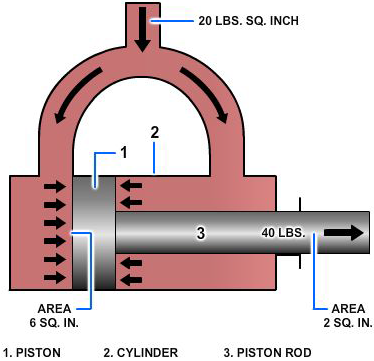
Consider the special situation shown in Figure 2-12. Here, a single piston (1) in a cylinder (2) has a piston rod (3) attached to one of its sides. The piston rod extends out of one end of the cylinder. Fluid under pressure is admitted equally to both ends of the cylinder. The opposed faces of the piston (1) behave like two pistons acting against each other. The area of one face is the full cross-sectional area of the cylinder, say 6 square inches, while the area of the other face is the area of the cylinder minus the area of the piston rod, which is 2 square inches. This leaves an effective area of 4 square inches on the right face of the piston. The pressure on both faces is the same, in this case, 20 psi. Recall that, according to Pascal's Law, a pressure exerted on a piston produces an equal increase in pressure on another piston in the system. If the second piston has an area 10 times that of the first, the force on the second piston is 10 times greater, though the pressure is the same as that on the first piston. This rule is shown in Figure 2-12, as the force pushing the piston to the right is its area times the pressure, or 120 pounds (20 x 6). Likewise, the force pushing the piston to the left is its area times the pressure, or 80 pounds (20 x 4). Therefore, there is a net unbalanced force of 40 pounds acting to the right, and the piston will move in that direction. The net effect is the same as if the piston and the cylinder had the same cross-sectional area as the piston rod.
Volume and Distance Factors
You have learned that if a force is applied to a system and the cross-sectional areas of the input and output pistons are equal, as in Figures 2-9 and 2-10, the force on the input piston will support an equal resistant force on the output piston. The pressure of the liquid at this point is equal to the force applied to the input piston divided by the piston's area. Let us now look at what happens when a force greater than the resistance is applied to the input piston.
In the system illustrated in Figure 2-9, assume that the resistance force on the output piston is 100 psi. If a force slightly greater than 100 pounds is applied to the input piston, the pressure in the system will be slightly greater than 10 psi. This increase in pressure will overcome the resistance force on the output piston. Assume that the input piston is forced downward 1 inch. The movement displaces 10 cubic inches of fluid. The fluid must go somewhere. Since the system is closed and the fluid is practically incompressible, the fluid will move to the right side of the system. Because the output piston also has a cross-sectional area of 10 square inches, it will move 1 inch upward to accommodate the 10 cubic inches of fluid. You may generalize this by saying that if two pistons in a closed system have equal cross-sectional areas and one piston is pushed and moved, the other piston will move the same distance, though in the opposite direction. This is because a decrease in volume in one part of the system is balanced by one equal increase in volume in another part of the system.
Apply this reasoning to the system in Figure 2-11. If the input piston is pushed down a distance of 1 inch, the volume of fluid in the left cylinder will decrease by 2 cubic inches. At the same time, the volume in the right cylinder will increase by 2 cubic inches. Since the diameter of the right cylinder cannot change, the piston must move upward to allow the volume to increase. The piston will move a distance equal to the volume increase divided by the surface area of the piston (equal to the surface area of the cylinder). In this example, the piston will move one-tenth of an inch (2 cu in ÷ 20 in2). This leads to the second basic rule for a fluid power system that contains two pistons: The distances the pistons move are inversely proportional to the areas of the pistons. Or more simply, if one piston is smaller than the other, the smaller piston must move a greater distance than the larger piston any time the pistons move.
Liquids in Motion
In the operation of fluid power systems, there must be a flow of fluid. The amount of flow will vary from system to system. To understand fluid power systems in action, it is necessary to understand some of the characteristics of liquids in motion.
Liquids in motion have characteristics different from liquids at rest. Frictional resistances within a fluid (viscosity) and inertia contribute to these differences. (Viscosity is discussed in chapter 3.) Inertia, which means the resistance a mass offers to being set in motion, will be discussed later in this section. There are other relationships of liquids in motion with which you must become familiar. Among these is volume of flow (flow rate), velocity of flow (velocity of fluid), streamline (laminar) and, turbulent flow that occur in flow.
Volume and Velocity of Flow
The volume of a liquid passing a point in a given time is known as its volume of flow or flow rate. The volume of flow is usually expressed in gallons per minute (gpm) and is associated with relative pressures of the liquid, such as 5 gpm at 40 psi.
The velocity of flow or velocity of the fluid is defined as the average speed at which the fluid moves past a given point. It is usually expressed in feet per second (fps) or feet per minute (fpm). Velocity of flow is an important consideration in sizing the hydraulic lines.
Volume and velocity of flow are often considered together. With other conditions unaltered — that is, with volume of input unchanged — the velocity of flow increases as the cross section or size of the pipe decreases, and the velocity of flow decreases as the cross section increases. For example, the velocity of flow is slow at wide parts of a stream and rapid at narrow parts, yet the volume of water passing each part of the stream is the same.
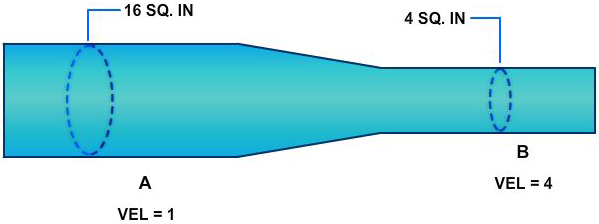
In Figure 2-13, if the cross-sectional area of the pipe is 16 square inches at point A and 4 square inches at point B, we can calculate the relative velocity of flow using the flow equation
where Q is the volume of flow, v is the velocity of flow, and A is the cross-sectional area of the liquid. Since the volume of flow at point A, Q1, is equal to the volume of flow at point B, Q2, we can use equation 2-7 to determine the ratio of the velocity of flow at point A, v1, to the velocity of flow at point B, v2.
Since Q1 = Q2, A1v1 = A2v2
From Figure 2-13; A1 = 16 in2, A2 = 4 in2
Substituting: 16v1 = 4v2 or v2 = 4v1
Therefore, the velocity of flow at point B is four times the velocity of flow at point A.
Volume of Flow and Speed
If you consider the cylinder volume you must fill and the distance the piston must travel, you can relate the volume of flow to the speed of the piston. The volume of the cylinder is found by multiplying the piston area by the length the piston must travel (stroke).
Suppose you have determined that two cylinders have the same volume and that one cylinder is twice as long as the other. In this case, the cross-sectional area of the longer tube will be half of the cross-sectional area of the other tube. If fluid is pumped into each cylinder at the same rate, both pistons will reach their full travel at the same time. However, the piston in the longer cylinder must travel twice as fast because it has twice as far to go.
There are two ways of controlling the speed of the piston: (1) by varying the size of the cylinder and (2) by varying the volume of flow (gpm) to the cylinders. (Hydraulic cylinders are discussed in detail in chapter 10.)
Streamline and Turbulent Flow
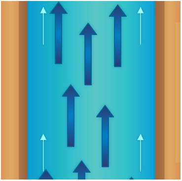
At low velocities or in tubes of small diameter, flow is streamlined. This means that a given particle of fluid moves straight forward without bumping into other particles and without crossing their paths. Streamline flow is often referred to as laminar flow, which is defined as a flow situation in which fluid moves in parallel laminae or layers. As an example of streamline flow, consider Figure 2-14, which illustrates an open stream flowing at a slow, uniform rate.
If the stream narrows, however, and the volume of flow remains the same, the velocity of flow increases. If the velocity increases sufficiently, the water becomes turbulent (Figure 2-15). Swirls, eddies, and cross-motions are set up in the water.
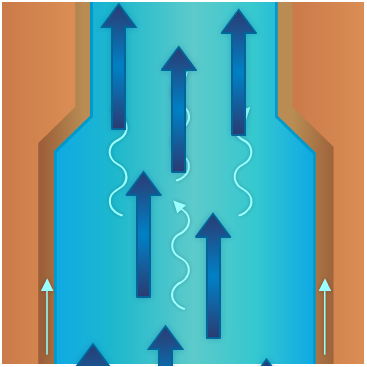
Particles of fluid flowing in pipes act in the same manner. The flow is streamlined if the fluid flows slowly enough, and remains streamlined at greater velocities if the diameter of the pipe is small. The flow of a fluid is turbulent as velocity is increased and the center of flow shifts from the center to the walls of the pipe. Turbulent flow will occur when its velocity is greater than critical velocity. Critical velocity of a fluid is that velocity up to which the fluid flow is streamlined and above which its flow becomes turbulent. When the velocity of a fluid exceeds the critical velocity, the paths and velocities of the fluid particles begin to change continuously and randomly. The flow loses all its orderliness and is called turbulent flow.
While a high velocity of flow will produce turbulence in any pipe, other factors contribute to turbulence. Among these are the roughness of the inside of the pipe, obstructions, the degree of curvature of bends, and the number of bends in the pipe. In setting up or maintaining fluid power systems, care should be taken to eliminate or minimize as many causes of turbulence as possible, since the energy consumed by turbulence is wasted.
While designers of fluid power equipment do what they can to minimize turbulence, it cannot be avoided. For example, at 68 degrees Fahrenheit (°F), flow becomes turbulent at velocities over approximately 6 inches per second in a 4-inch pipe or about 3 inches per second in a 6-inch pipe. These velocities are far below those commonly encountered in fluid power systems, where velocities of 5 feet per second and above are common. In streamlined flow, losses due to friction increase directly with velocity. With turbulent flow these losses increase much more rapidly.
Factors Involved in Flow
An understanding of the behavior of fluids in motion, or solids for that matter, requires an understanding of the term inertia. Inertia is the term used by scientists to describe the property possessed by all forms of matter that makes the matter resist being moved if it is at rest, and likewise, resist any change in its rate of motion if it is moving.
The basic statement covering inertia is Newton's first law of motion — inertia. Sir Isaac Newton was a British philosopher and mathematician. His first law states: A body at rest tends to remain at rest, and a body in motion tends to remain in motion at the same speed and direction, unless acted on by some unbalanced force. This simply says what you have learned by experience — that you must push an object to start it moving and push it in the opposite direction to stop it again.
A familiar illustration is the effort a pitcher must exert to make a fast pitch and the opposition the catcher must put forth to stop the ball. Similarly, considerable work must be performed by the engine to make an automobile begin to roll; although, after it has attained a certain velocity, it will roll along the road at uniform speed if just enough effort is expended to overcome friction, while brakes are necessary to stop its motion. Inertia also explains the kick or recoil of guns and the tremendous striking force of projectiles.
Inertia and Force
To overcome the tendency of an object to resist any change in its state of rest or motion, some force that is not otherwise canceled or unbalanced must act on the object. Some unbalanced force must be applied whenever fluids are set in motion or increased in velocity; while conversely, forces are made to do work elsewhere whenever fluids in motion are retarded or stopped.
There is a direct relationship between the magnitude of the force exerted and the inertia against which it acts. This force is dependent on two factors: (1) the mass of the object (which is proportional to its weight), and (2) the rate at which the velocity of the object is changed. The rule is that the force in pounds required to overcome inertia is equal to the weight of the object multiplied by the change in velocity, measured in feet per second, and divided by 32 times the time in seconds required to accomplish the change. Thus, the rate of change in velocity of an object is proportional to the force applied. The number 32 appears because it is the conversion factor between weight and mass.
There are five physical factors that can act on a fluid to affect its behavior. All of the physical actions of fluids in all systems are determined by the relationships of these five factors to each other. Summarizing, these five factors are as follows:
- Gravity, which acts at all times on all bodies, regardless of other forces.
- Atmospheric pressure, which acts on any part of a system exposed to the open air.
- Specific applied forces, which may or may not be present, but which, in any event, are entirely independent of the presence or absence of motion.
- Inertia, which comes into play whenever there is a change from rest to motion or the opposite, or whenever there is a change in direction or in rate of motion.
- Friction, which is always present whenever there is motion.
A possible relationship of these factors with respect to a particle of fluid (P) in a system is shown in Figure 2-16. The different forces are shown in terms of head, or in other words, in terms of vertical columns of fluid required to provide the forces. At the particular moment under consideration, a particle of water (P) is being acted on by applied force (A), by atmospheric pressure (B), and by gravity (C) produced by the weight of the fluid standing over it. The particle possesses sufficient inertia or velocity head to rise to level P1, since head equivalent to F was lost in friction as P passed through the system. Since atmospheric pressure (B) acts downward on both sides of the system, what is gained on one side is lost on the other.
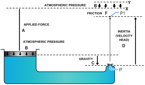
If all the pressure acting on P to force it through the nozzle could be recovered in the form of elevation head, it would rise to level Y. If account is taken of the balance in atmospheric pressure, in a frictionless system, P would rise to level X, or precisely as high as the sum of the gravity head and the head equivalent to the applied force.
Kinetic Energy
It was previously pointed out that a force must be applied to an object in order to give it a velocity or to increase the velocity it already has. Whether the force begins or changes velocity, it acts over a certain distance. A force acting over a certain distance is work. Work and all forms into which it can be changed are classified as energy. Obviously then, energy is required to give an object velocity. The greater the energy used, the greater the velocity will be.
Disregarding friction, for an object to be brought to rest or for its motion to be slowed down, a force opposed to its motion must be applied to it. This force also acts over some distance. In this way energy is given up by the object and delivered in some form to whatever opposes its continuous motion. The moving object is therefore a means of receiving energy at one place (where its motion is increased) and delivering it to another point (where it is stopped or retarded). While it is in motion, it is said to contain this energy as energy of motion or kinetic energy.
Since energy can never be destroyed, it follows that if friction is disregarded the energy delivered to stop the object will exactly equal the energy that was required to increase its speed. At all times the amount of kinetic energy possessed by an object depends on its weight and the velocity at which it is moving.
The mathematical relationship for kinetic energy is stated in the following rule: "Kinetic energy in foot-pounds is equal to the force in pounds which created it, multiplied by the distance through which it was applied, or to the weight of the moving object in pounds, multiplied by the square of its velocity in feet per second, and divided by 64."
The relationship between inertia forces, velocity, and kinetic energy can be illustrated by analyzing what happens when a gun fires a projectile against the armor of an enemy ship (Figure 2-17). The explosive force of the powder in the breach pushes the projectile out of the gun, giving it a high velocity. Because of its inertia, the projectile offers opposition to this sudden velocity and a reaction is set up that pushes the gun backward (kick or recoil). The force of the explosion acts on the projectile throughout its movement in the gun. This is force acting through a distance producing work. This work appears as kinetic energy in the speeding projectile. The resistance of the air produces friction, which uses some of the energy and slows down the projectile. Eventually, however, the projectile hits its target and, because of the inertia, tries to continue moving. The target, being relatively stationary, tends to remain stationary because of its inertia. The result is that a tremendous force is set up that either leads to the penetration of the armor or the shattering of the projectile. The projectile is simply a means of transferring energy, in this instance for destructive purpose, from the gun to the enemy ship. This energy is transmitted in the form of energy of motion or kinetic energy.
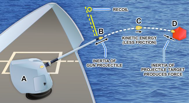
A similar action takes place in a fluid power system in which the fluid takes the place of the projectile. For example, the pump in a hydraulic system imparts energy to the fluid, which overcomes the inertia of the fluid at rest and causes it to flow through the lines. The fluid flows against some type of actuator that is at rest. The fluid tends to continue flowing, overcomes the inertia of the actuator, and moves the actuator to do work. Friction uses up a portion of the energy as the fluid flows through the lines and components.
Relationship of Force, Pressure, and Head
In dealing with fluids, forces are usually considered in relation to the areas over which they are applied. As previously discussed, a force acting over a unit area is a pressure, and pressure can alternately be stated in pounds per square inch or in terms of head, which is the vertical height of the column of fluid whose weight would produce that pressure.
In most of the applications of fluid power in the Navy, applied forces greatly outweigh all other forces, and the fluid is entirely confined. Under these circumstances it is customary to think of the forces involved in terms of pressures. Since the term head is encountered frequently in the study of fluid power, it is necessary to understand what it means and how it is related to pressure and force.
All five of the factors that control the actions of fluids can, of course, be expressed either as force, or in terms of equivalent pressures or head. In each situation, the different factors are referred to in the same terms, since they can be added and subtracted to study their relationship to each other.
At this point you need to review some terms in general use. Gravity head, when it is important enough to be considered, is sometimes referred to as head. The effect of atmospheric pressure is referred to as atmospheric pressure. (Atmospheric pressure is frequently and improperly referred to as suction.) Inertia effect, because it is always directly related to velocity, is usually called velocity head; and friction, because it represents a loss of pressure or head, is usually referred to as friction head.
Static and Dynamic Factors
Gravity, applied forces, and atmospheric pressure are static factors that apply equally to fluids at rest or in motion, while inertia and friction are dynamic factors that apply only to fluids in motion. The mathematical sum of gravity, applied force, and atmospheric pressure is the static pressure obtained at any one point in a fluid at any given time. Static pressure exists in addition to any dynamic factors that may also be present at the same time.
Remember, Pascal's law states that a pressure set up in a fluid acts equally in all directions and at right angles to the containing surfaces. This covers the situation only for fluids at rest or practically at rest. It is true only for the factors making up static head. Obviously, when velocity becomes a factor it must have a direction, and as previously explained, the force related to the velocity must also have a direction, so that Pascal's law alone does not apply to the dynamic factors of fluid power.
The dynamic factors of inertia and friction are related to the static factors. Velocity head and friction head are obtained at the expense of static head. However, a portion of the velocity head can always be reconverted to static head. Force, which can be produced by pressure or head when dealing with fluids, is necessary to start a body moving if it is at rest, and is present in some form when the motion of the body is arrested; therefore, whenever a fluid is given velocity, some part of its original static head is used to impart this velocity, which then exists as velocity head.
Bernoulli's Principle
Consider the system illustrated in Figure 2-18. Chamber A is under pressure and is connected by a tube to chamber B, which is also under pressure. The pressure in chamber A is static pressure of 100 psi. The pressure at some point (X) along the connecting tube consists of a velocity pressure of 10 psi exerted in a direction parallel to the line of flow, plus the unused static pressure of 90 psi, which still obeys Pascal's law and operates equally in all directions. As the fluid enters chamber B, it is slowed down, and its velocity is changed back to pressure. The force required to absorb its inertia equals the force required to start the fluid moving originally, so that the static pressure in chamber B is equal to that in chamber A.

This situation (Figure 2-18) disregards friction; therefore, it would not be encountered in actual practice. Force or head is also required to overcome friction but, unlike inertia effect, this force cannot be recovered again, although the energy represented still exists somewhere as heat. Therefore, in an actual system the pressure in chamber B would be less than in chamber A by the amount of pressure used in overcoming friction along the way.
At all points in a system the static pressure is always the original static pressure, less any velocity head at the point in question and less the friction head consumed in reaching that point. Since both the velocity head and the friction head represent energy that came from the original static head, and since energy cannot be destroyed, the sum of the static head, the velocity head, and the friction head at any point in the system must add up to the original static head. This is known as Bernoulli's principle, which states: For the horizontal flow of fluid through a tube, the sum of the pressure and the kinetic energy per unit volume of the fluid is constant. This principle governs the relations of the static and dynamic factors concerning fluids, while Pascal's law states the manner in which the static factors behave when taken by themselves.
Minimizing Friction
Fluid power equipment is designed to reduce friction to the lowest possible level. Volume and velocity of flow are made the subject of careful study. The proper fluid for the system is chosen. Clean, smooth pipe of the best dimensions for the particular conditions is used, and it is installed along as direct a route as possible. Sharp bends and sudden changes in cross-sectional areas are avoided. Valves, gauges, and other components are designed to interrupt flow as little as possible. Careful thought is given to the size and shape of the openings. The systems are designed so they can be kept clean inside and variations from normal operation can easily be detected and remedied.
Operation of Hydraulic Components
To transmit and control power through pressurized fluids, an arrangement of interconnected components is required. Such an arrangement is commonly referred to as a system. The number and arrangement of the components vary from system to system, depending on the particular application. In many applications, one main system supplies power to several subsystems, which are sometimes referred to as circuits. The complete system may be a small compact unit; more often, however, the components are located at widely separated points for convenient control and operation of the system.
The basic components of a fluid power system are essentially the same, regardless of whether the system uses a hydraulic or a pneumatic medium. There are five basic components used in a system. These basic components are as follows:
- Reservoir or receiver (depending on system type).
- Pump or compressor.
- Lines (pipe, tubing, or flexible hose).
- Directional control valve.
- Actuating device.
Several applications of fluid power require only a simple system; that is, a system that uses only a few components in addition to the five basic components. A few of these applications are presented in the following paragraphs. We will explain the operation of these systems briefly at this time so you will know the purpose of each component and can better understand how hydraulics is used in the operation of these systems.
Hydraulic Jack
The hydraulic jack is perhaps one of the simplest forms of a fluid power system. By moving the handle of a small device, an individual can lift a load weighing several tons. A small initial force exerted on the handle is transmitted by a fluid to a much larger area. To understand this better, study Figure 2-19. The small input piston has an area of 5 square inches and is directly connected to a large cylinder with an output piston having an area of 250 square inches. The top of this piston forms a lift platform.
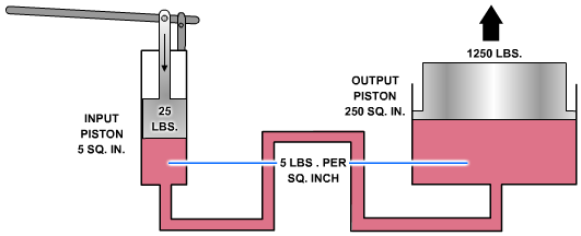
If a force of 25 pounds is applied to the input piston, it produces a pressure of 5 psi in the fluid, that is, of course, if a sufficient amount of resistant force is acting against the top of the output piston. Disregarding friction loss, this pressure acting on the 250-square-inch area of the output piston will support a resistance force of 1,250 pounds. In other words, this pressure could overcome a force of slightly under 1,250 pounds. An input force of 25 pounds has been transformed into a working force of more than half a ton; however, for this to be true, the distance traveled by the input piston must be 50 times greater than the distance traveled by the output piston. Thus, for every inch that the input piston moves, the output piston will move only one-fiftieth of an inch.
This would be ideal if the output piston needed to move only a short distance. However, in most instances, the output piston would have to be capable of moving a greater distance to serve a practical application. The device shown in Figure 2-19 is not capable of moving the output piston farther than that shown; therefore, some other means must be used to raise the output piston to a greater height.
The output piston can be raised higher and maintained at this height if additional components are installed as shown in Figure 2-20. In this illustration the jack is designed so that it can be raised, lowered, or held at a constant height. These results are attained by introducing a number of valves and also a reserve supply of fluid to be used in the system.
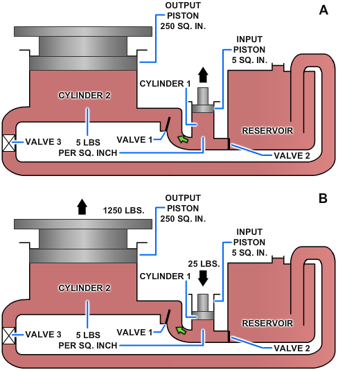
Notice that this system contains the five basic components — the reservoir; cylinder 1, which serves as a pump; valve 3, which serves as a directional control valve; cylinder 2, which serves as the actuating device; and lines to transmit the fluid to and from the different components. In addition, this system contains two valves, 1 and 2, whose functions are explained in the following discussion.
As the input piston is raised (Figure 2-20, view A), valve 1 is closed by the back pressure from the weight of the output piston. At the same time, valve 2 is opened by the head of the fluid in the reservoir. This forces fluid into cylinder 1. When the input piston is lowered (Figure 2-20, view B), a pressure is developed in cylinder 1. When this pressure exceeds the head in the reservoir, it closes valve 2. When it exceeds the back pressure from the output piston, it opens valve 1, forcing fluid into the pipeline. The pressure from cylinder 1 is thus transmitted into cylinder 2, where it acts to raise the output piston with its attached lift platform. When the input piston is again raised, the pressure in cylinder 1 drops below that in cylinder 2, causing valve 1 to close. This prevents the return of fluid and holds the output piston with its attached lift platform at its new level. During this stroke, valve 2 opens again, allowing a new supply of fluid into cylinder 1 for the next power (downward) stroke of the input piston. Thus, by repeated strokes of the input piston, the lift platform can be progressively raised. To lower the lift platform, valve 3 is opened, and the fluid from cylinder 2 is returned to the reservoir.
Hydraulic Brakes
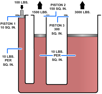
The hydraulic brake system used in the automobile is a multiple piston system. A multiple piston system allows forces to be transmitted to two or more pistons in the manner indicated in Figure 2-21. Note that the pressure set up by the force applied to the input piston (1) is transmitted undiminished to both output pistons (2 and 3), and that the resultant force on each piston is proportional to its area. The multiplication of forces from the input piston to each output piston is the same as that explained earlier.
The hydraulic brake system from the master cylinders to the wheel cylinders on most automobiles operates in a way similar to the system illustrated in Figure 2-22.
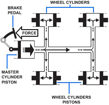
When the brake pedal is depressed, the pressure on the brake pedal moves the piston within the master cylinder, forcing the brake fluid from the master cylinder through the tubing and flexible hose to the wheel cylinders. The wheel cylinders contain two opposed output pistons, each of which is attached to a brake shoe fitted inside the brake drum. Each output piston pushes the attached brake shoe against the wall of the brake drum, thus retarding the rotation of the wheel. When pressure on the pedal is released, the springs on the brake shoes return the wheel cylinder pistons to their released positions. This action forces the displaced brake fluid back through the flexible hose and tubing to the master cylinder.
The force applied to the brake pedal produces a proportional force on each of the output pistons, which in turn apply the brake shoes frictionally to the turning wheels to retard rotation.
As previously mentioned, the hydraulic brake system on most automobiles operates in a similar way, as shown in Figure 2-22. It is beyond the scope of this manual to discuss the various brake systems.
PDH Classroom offers a continuing education course based on this forces in liquids reference page. This course can be used to fulfill PDH credit requirements for maintaining your PE license.
Now that you've read this reference page, earn credit for it!
