Vectors
This page provides the chapter on vectors from the "DOE Fundamentals Handbook: Classical Physics," DOE-HDBK-1010-92, U.S. Department of Energy, June 1992.
Other related chapters from the "DOE Fundamentals Handbook: Classical Physics" can be seen to the right.
Scalar and Vector Quantities
Scalars are quantities that have magnitude only; they are independent of direction. Vectors have both magnitude and direction. The length of a vector represents magnitude. The arrow shows direction.
Scalar Quantities
Most of the physical quantities encountered in physics are either scalar or vector quantities. A scalar quantity is defined as a quantity that has magnitude only. Typical examples of scalar quantities are time, speed, temperature, and volume. A scalar quantity or parameter has no directional component, only magnitude. For example, the units for time (minutes, days, hours, etc.) represent an amount of time only and tell nothing of direction. Additional examples of scalar quantities are density, mass, and energy.
Vector Quantities
A vector quantity is defined as a quantity that has both magnitude and direction. To work with vector quantities, one must know the method for representing these quantities.
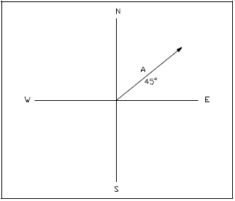
Magnitude, or "size" of a vector, is also referred to as the vector's "displacement." It can be thought of as the scalar portion of the vector and is represented by the length of the vector. By definition, a vector has both magnitude and direction. Direction indicates how the vector is oriented relative to some reference axis, as shown in Figure 1.
Using north/south and east/west reference axes, vector "A" is oriented in the NE quadrant with a direction of 45° north of the EW axis. Giving direction to scalar "A" makes it a vector. The length of "A" is representative of its magnitude or displacement.
To help distinguish between a scalar and a vector, let's look at an example where the only information known is that a car is moving at 50 miles per hour. The information given (50 mph) only refers to the car's speed, which is a scalar quantity. It does not indicate the direction the car is moving. However, the same car traveling at 50 mph due east indicates the velocity of the car because it has magnitude (50 mph) and direction (due east); therefore, a vector is indicated. When a vector is diagrammed, a straight line is drawn to show the unit of length. An arrow is drawn on one end of the line. The length of the line represents the magnitude of the vector, and the arrow represents the direction of the vector.
Description of a Simple Vector
Vectors are simple straight lines used to illustrate the direction and magnitude of certain quantities. Vectors have a starting point at one end (tail) and an arrow at the opposite end (head), as shown in Figure 2.

Examples of Vector Quantities
Displacement, velocity, acceleration, and force are examples of vector quantities. Momentum and magnetic field strength are also good examples of vector quantities, although somewhat more difficult to understand. In each of these examples, the main ingredients of magnitude and direction are present.
We have a number of structural calculators to choose from. Here are just a few:
Vector Identification
Vectors are symbolized in specific ways in texts and on graphs, using letters or rectangular coordinates.
In Written Materials
In textbooks, vector quantities are often represented by simply using a boldfaced letter (A, B, C, R). Particular quantities are predefined (F - force, V - velocity, and A - acceleration). Vector quantities are sometimes represented by A, B, C, R. Regardless of the convention used, specific vector quantities must include magnitude and direction (for example, 50 mph due north, or 50 lbf at 90° ).
Graphic Representation
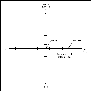
Vector quantities are graphically represented using the rectangular coordinate system, a two-dimensional system that uses an x-axis and a y-axis. The x-axis is a horizonal straight line. The y-axis is a vertical straight line, perpendicular to the x-axis. An example of a rectangular system is shown in Figure 3.
The intersection of the axes is called the point of origin. Each axis is marked off in equal divisions in all four directions from the point of origin. On the horizonal axis (x), values to the right of the origin are positive (+). Values to the left of the origin are negative (−). On the vertical axis (y), values above the point of origin are positive (+). Values below the origin are negative (−). It is very important to use the same units (divisions) on both axes.
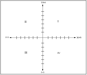
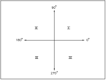
The rectangular coordinate system creates four infinite quadrants. Quadrant I is located above and to the right of the origin. Quadrant II is located above and to the left of the origin. Quadrant III is situated to the left and below the origin, and Quadrant IV is located below and to the right of the origin (see Figure 3).
Graphic Representation of Vectors
With the coordinate system defined, the following explanation will illustrate how to locate vectors in that system.
First, using a ruler and graph paper, a rectangular coordinate system is laid out as described in the previous section. The x- and y-axes are labeled. Equal divisions are marked off in all four directions. Those to the right and above the point of origin are labeled positive (+). Those to the left and below the point of origin are labeled negative (−).
Beginning at the point of origin (intersection of the axes), a line segment of the proper length is shown along the x-axis, in the positive direction. This line segment represents the vector magnitude, or displacement. An arrow is placed at the "head" of the vector to indicate direction. The "tail" of the vector is located at the point of origin (see Figure 4).
When vectors are drawn that do not fall on the x- or y-axes, the tail is located at the point of origin. Depending on the vector description, there are two methods of locating the head of the vector. If coordinates (x,y) are given, these values can be plotted to locate the vector head. If the vector is described in degrees, the line segment can be rotated counterclockwise from the x-axis to the proper orientation, as shown in Figure 5.
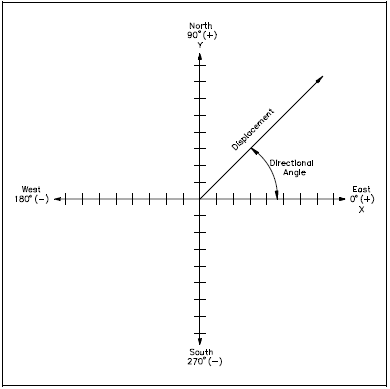
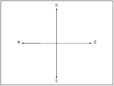
Because the x- and y-axes define direction, conventional directional coordinates and degrees may also be used to identify the x- and y-axes (see Figures 6 and 7).
Vectors: Resultants and Components
A resultant is a single vector which represents the combined effect of two or more other vectors (called components). The components can be determined either graphically or by using trigonometry.
Resultant
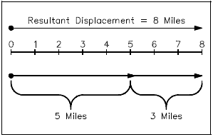
When two or more vectors are added they yield the sum or resultant vector. A resultant vector is the result or sum of vector addition. Vector addition is somewhat different from addition of pure numbers unless the addition takes place along a straight line. In the latter case, it reduces to the number line of standards or scale addition. For example, if one walks five miles east and then three miles east, he is eight miles from his starting point. On a graph (Figure 8), the sum of the two vectors, i.e., the sum of the five miles plus the three mile displacement, is the total or resultant displacement of eight miles.
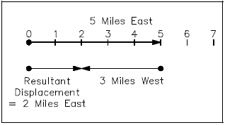
Similarly, if one walks five miles east and then three miles west, the resultant displacement is two miles east (Figure 9).
The vector diagrams of Figure 8 and Figure 9 are basically scale diagrams of what is happening in the real world of addition of vector quantities.
Consider next the addition of vector quantities which are not in a straight line. For example, consider the resultant displacement when a person travels four miles east and then three miles north. Again a scale drawing (Figure 10) is in order. Use a scale of 1 inch = 1 mile.
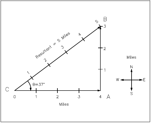
When drawing a scale drawing, one draws a straight line from the origin C to the final position B to represent the net or resultant displacement. Drawing the straight line CB and measuring its length, one should obtain about 5 inches. Then, since the scale of the drawing is 1 inch = 1 mile, this is used as a conversion factor giving 5 inches × \({1 ~\text{mile} \over \text{inch}}\) = 5 miles as the displacement.
Using a protractor or trigonometry, the acute angle ACB can be determined to be about 37°. Thus, the resultant (or vector sum) of traveling 4 miles east plus 3 miles north is a displacement of 5 miles at 37 degrees north of east.
It is left as an exercise for the student to show that vector addition is commutative, using the above example. Specifically, make a scale drawing showing that traveling 3 miles north and then 4 miles east yields the same resultant as above.
It is also reasonably obvious that more than two vectors can be added. One can travel three miles east and then three miles north and then three miles west and arrive at a point three miles north of the starting point. The sum of these three displacements is a resultant displacement of three miles north. (If this is not immediately apparent, sketch it.)
A student problem is to find the net or resultant displacement if a person travels 9 miles south and then 12 miles east and then 25 miles north. Make a scale drawing and determine the magnitude and direction of the resultant displacement. A scale of 2 miles per centimeter or 4 miles per inch will fit the drawing on standard paper.
Answer: About 20 miles at 53° north of east.
Vector Components
Components of a vector are vectors, which when added, yield the vector. For example, as shown in the previous section (Figure 10), traveling 3 miles north and then 4 miles east yields a resultant displacement of 5 miles, 37° north of east. This example demonstrates that component vectors of any two non-parallel directions can be obtained for any resultant vector in the same plane. For the purposes of this manual, we restrict our discussions to two dimensional space. The student should realize that vectors can and do exist in three dimensional space.
One could write an alternate problem: "If I am 5 miles from where I started northeast along a line 37° N of east, how far north and how far east am I from my original position?" Drawing this on a scale drawing, the vector components in the east and north directions can be measured to be about 4 miles east and 3 miles north. These two vectors are the components of the resultant vector of 5 miles, 37° north of east.
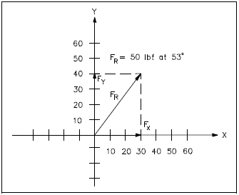
Component vectors can be determined by plotting them on a rectangular coordinate system. For example, a resultant vector of 5 units at 53° can be broken down into its respective x and y magnitudes. The x value of 3 and the y value of 4 can be determined using trigonometry or graphically. Their magnitudes and position can be expressed by one of several conventions including: (3,4), (x=3, y=4), (3 at 0°, 4 at 90°), and (5 at 53°). In the first expression, the first term is the x-component (Fx), and the second term is the y-component (Fy) of the associated resultant vector.
As in the previous example, if only the resultant is given, instead of component coordinates, one can determine the vector components as illustrated in Figure 11. First, plot the resultant on rectangular coordinates and then project the vector coordinates to the axis. The length along the x-axis is Fx, and the length along the y-axis is Fy. This method is demonstrated in the following example.
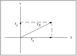
For the resultant vector shown in Figure 12, determine the component vectors given FR = 50 lbf at 53°. First, project a perpendicular line from the head of FR to the x-axis and a similar line to the y-axis. Where the projected lines meet, the axes determine the magnitude size of the component vectors. In this example, the component vectors are 30 lbf at 0° (Fx) and 40 lbf at 90° (Fy). If FR had not already been drawn, the first step would have been to draw the vector.
As an exercise, the student should graphically find the easterly and northerly components of a 13 mile displacement at 22.6° north of east. The correct answer is 5 miles east and 12 miles north.
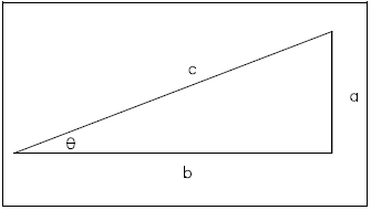
Trigonometry may also be used to determine vector components. Before explaining this method, it may be helpful to review the fundamental trigonometric functions. Recall that trigonometry is a branch of mathematics that deals with the relationships between angles and the length of the sides of triangles. The relationship between an acute angle of a right triangle, shown in Figure 13, and its sides is given by three ratios.
Before attempting to calculate vector components, first make a rough sketch that shows the approximate location of the resultant vector in an x-y coordinate system. It is helpful to form a visual picture before selecting the correct trigonometric function to be used. Consider the example of Figure 12, that was used previously. This time the component vectors will be calculated.
| Example 1: | Determine the component vectors, Fx and Fy, for FR = 50 lbf at 53° in Figure 14. Use trigonometric functions. |
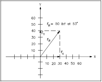
Fx is calculated as follows:
cosθ = adjacent/hypotenuse
cosθ = Fx/FR
Fx = FR cosθ
Fx = (50)(cos53°)
Fx = (50)(0.6018)
Fx = 30 lbf on x-axis
Fy is calculated as follows:
sinθ = opposite/hypotenuse
sinθ = Fy/FR
Fy = FR sinθ
Fy = (50)(sin53°)
Fy = (50)(0.7986)
Fy = 40 lbf on x-axis
Therefore, the components for FR are Fx = 30 lbf at 0° and Fy = 40 lbf at 90°. Note that this result is identical to the result obtained using the graphic method.
| Example 2: | What are the component vectors, given FR = 80 lbf at 220°? See Figure 15. |
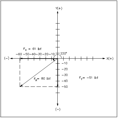
Fx is calculated as follows:
cosθ = adjacent/hypotenuse
cosθ = Fx/FR
Fx = FR cosθ
Fx = (80)(cos220°)
Fx = (80)(-0.766)
Fx = -61 lbf at 0° or 61 lbf at 180°
Fy is calculated as follows:
sinθ = opposite/hypotenuse
sinθ = Fy/FR
Fy = FR sinθ
Fy = (80)(sin220°)
Fy = (80)(-0.6428)
Fy = -51 lbf at 90° or 51 lbf at 270°
Therefore, the components for FR are Fx = 61 lbf at 180° and Fy = 51 lbf at 270°.
We have a number of structural calculators to choose from. Here are just a few:
Graphic Method of Vector Addition
Vectors are added to determine the magnitude and direction of the resultant.
Vector Addition
Component vectors are added to determine the resultant vector. For example, when two or more forces are acting on a single object, vector addition is used to determine the direction and magnitude of the net (resultant) force on the object. Consider an airplane that travels due east for 100 miles at 500 mph, then NE for 50 miles at 400 mph, and finally north for 500 miles at 500 mph. Vector addition can be used to determine the net distance the airplane is from its point of origin or to predict when it will arrive at its destination.
Methods Used to Add Vectors
Several methods have been developed to add vectors. In this chapter, the graphic method will be explained. The next chapter will explain the component addition method. Either one of these methods will provide fairly accurate results. If a high degree of accuracy is required, an analytical method using geometric and trigonometric functions is required.
Using the Graphic Method
Before attempting to use this method, the following equipment is needed: standard linear (nonlog) graph paper, ruler, protractor, and pencil. The graphic method utilizes a five-step process.
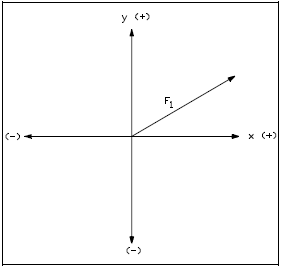
Step 1. Plot the first vector on the rectangular (x-y) axes.
- Ensure that the same scale is used on both axes.
- Place the tail (beginning) of the first vector at the origin of the axes as shown in Figure 16.
Step 2. Draw the second vector connected to the end of the first vector.
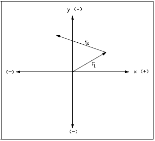
- Start the tail of the second vector at the head of the first vector.
- Ensure that the second vector is also drawn to scale.
- Ensure proper angular orientation of the second vector with respect to the axes of the graph (see Figure 17).
Step 3. Add other vectors sequentially.
- Add one vector at a time.
- Always start the tail of the new vector at the head of the previous vector.
- Draw all vectors to scale and with proper angular orientation.
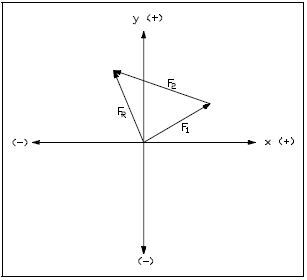
Step 4. When all given vectors have been drawn, draw and label a resultant vector, FR, from the point of origin of the axes to the head of the final vector.
- The tail of the resultant is the tail of the first vector drawn as shown in Figure 18.
- The head of the resultant is at the head of the last vector drawn.
Step 5. Determine the magnitude and direction of the resultant.
- Measure the displacement and angle directly from the graph using a ruler and a protractor.
- Determine the components of the resultant by projection onto the x- and y-axes.
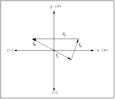
| Example 1: | What are the magnitude and direction of the resultant for the following: F1 = 3 units at 300°, F2 = 4 units at 60°, and F3 = 8 units at 180°? The three vectors and their resultant are shown in Figure 19. |
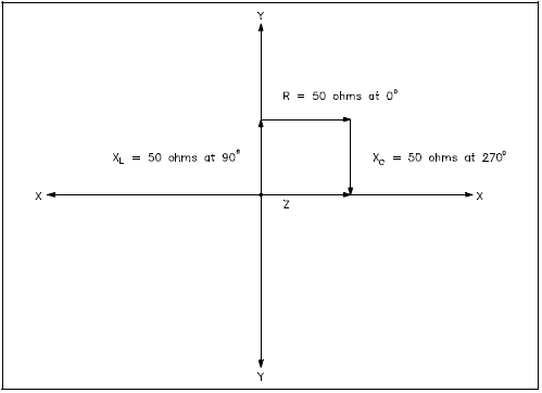
| Example 2: | Given XL = 50 Ohms at 90°, R = 50 Ohms at 0°, and XC = 50 Ohms at 270°, what is the Resultant Z? (See Figure 20) Note: XL is inductive reactance, XC is capacitive reactance and Z is impedance. |
| Answer: | Z = 50 Ohms at 0° |
Component Addition Method
Vector components are added along each axis to determine the magnitude and direction of the resultant.
An Explanation of Components
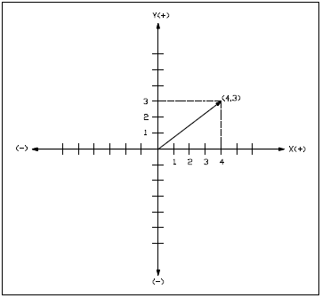
The component addition method refers to the addition of vector coordinates on a rectangular (x,y) coordinate system. Coordinates, as seen in previous examples, locate a specific point in the system. Relative to vectors, that specific point is the head of the vector. There are two ways to locate that point. The head can be located by counting the units along the x-axis and the units along the y-axis, as illustrated in Figure 21, where the point has coordinates (4,3); i.e., the x component has a magnitude of 4 and the y component has a magnitude of 3.
The head can also be found by locating a vector of the proper length on the positive side of the x-axis, with its tail at the intersection of the x- and y- axes. Then the vector is rotated a given number of degrees in the counterclockwise direction. In this example, the head of the vector is located five units at 36.9°. Five units is the length of the vector.
Using the Component Addition Method
To add vectors using the component addition method, use the following four step method.
| Step 1. | Determine x- and y-axes components of all original vectors. |
| Step 2. | Mathematically combine all x-axis components. Note: When combining, recognize that positive x components at 180° are equivalent to negative x components at 0° (+x at 180° = -x at 0°). |
| Step 3. | Mathematically combine all y-axis components (+y at 270° = -y at 90°). |
| Step 4. | Resulting (x,y) components are the (x,y) components of the resulting vector. |
The following examples illustrate vector addition using the component addition method.
Example 1:
Given the following vectors what are the coordinates of the resultant vector, that is, the sum of the vectors?
F1 = (4,10), F2 = (-6,4), F3 = (2,-4), and F4 = (10,-2)
| Step 1. | Determine the x- and y-axes components of all four original vectors. |
| x-axes components = 4, -6, 2, 10 y-axes components = 10, 4, -4, -2 |
|
| Step 2. | Mathematically combine all x-axis components. |
|
Fx = 4 + (-6) + 2 + 10 Fx = 4 - 6 + 2 + 10 Fx = 10 |
|
| Step 3. | Mathematically combine all y-axis components. |
|
Fy = 10 + 4 + (-4) + (-2) Fy = 10 + 4 - 4 - 2 Fy = 8 |
|
| Step 4. | Express the resultant vector. |
| The resultant components from the previous additions are the coordinates of the resultant, that is, FR = (10,8). |
| Example 2: | Determine the resultant, FR. |
| Given: |
F1 = 30 lbf at 0°, 10 lbf at 90° F2 = 50 lbf at 0°, 50 lbf at 90° F3 = 45 lbf at 180°, 30 lbf at 90° F4 = 15 lbf at 0°, 50 lbf at 270° |
Follow the sequence used in the first example. Remember that x at 180° is -x at 0°, and y at 270° is -y at 90°.
Fx = 30 + 50 + (-45) + 15 = 50 lbf
Fy = 10 + 50 + 30 + (-50) = 40 lbf
FR = 50 lbf at 0°, 40 lbf at 90°
We have a number of structural calculators to choose from. Here are just a few:
Analytical Method of Vector Addition
Vector components are added to determine the magnitude and direction of the resultant. Calculations using trigonometric functions are the most accurate method for making this determination.
The graphic and components addition methods of obtaining the resultant of several vectors described in the previous chapters can be hard to use and time consuming. In addition, accuracy is a function of the scale used in making the diagram and how carefully the vectors are drawn. The analytical method can be simpler and far more accurate than these previous methods.
Review of Mathematical Functions
In earlier mathematics lessons, the Pythagorean Theorem was used to relate the lengths of the sides of right triangles such as in Figure 22. The Pythagorean Theorem states that in any right triangle, the square of the length of the hypotenuse equals the sum of the squares of the lengths of the other two sides. This expression may be written as given in Equation 2-4.
| $$ c^2 = a^2 + b^2 $$ | or | $$ c = \sqrt{a^2 + b^2} $$ |

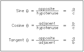
Also, recall the three trigonometric functions reviewed in an earlier chapter and shown in Figure 23. The cosine will be used to solve for Fx. The sine will be used to solve for Fy. Tangent will normally be used to solve for θ, although sine and cosine may also be used.
On a rectangular coordinate system, the sine values of θ are positive (+) in quadrants I and II and negative (−) in quadrants III and IV. The cosine values of θ are positive (+) in quadrants I and IV and negative (−) in quadrants II and III. Tangent values are positive (+) in quadrants I and III and negative (−) in quadrants II and IV.
When mathematically solving for tan 2, calculators will specify angles in quadrants I and IV only. Actual angles may be in quadrants II and III. Each problem should be analyzed graphically to report a realistic solution. Quadrant II and III angles may be obtained by adding or subtracting 180° from the value calculated.
Using the Analytical Method
To illustrate this method, consider this example: a man walks 3 miles in one direction, then turns 90° and continues to walk for an additional 4 miles. In what direction and how far is he from his starting point? The first step in solving this problem is to draw a simple sketch as shown in Figure 24.
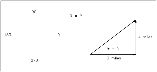
His net displacement is found using equation 2-4.
$$ R = \sqrt{a^2 + b^2} $$
$$ R = \sqrt{3^2 + 4^2} $$
$$ R = \sqrt{25} $$
R = 5 miles
His direction (angle of displacement) is found using the tangent function.
tan θ = opposite/adjacent
tan θ = a/b
tan θ = 4/3
tan θ = 1.33
θ = tan-1 1.33
θ = 53°
Therefore, his new location is 5 miles at 53° from his starting point.
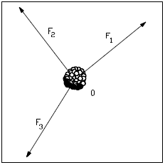
By carrying this approach a step further, a model has been developed for finding the resultant of several vectors. For the purpose of developing the model, consider three forces (F1, F2, and F3) acting on an object as shown in Figure 25. The goal is to find the resultant force (FR).
| Step 1: |
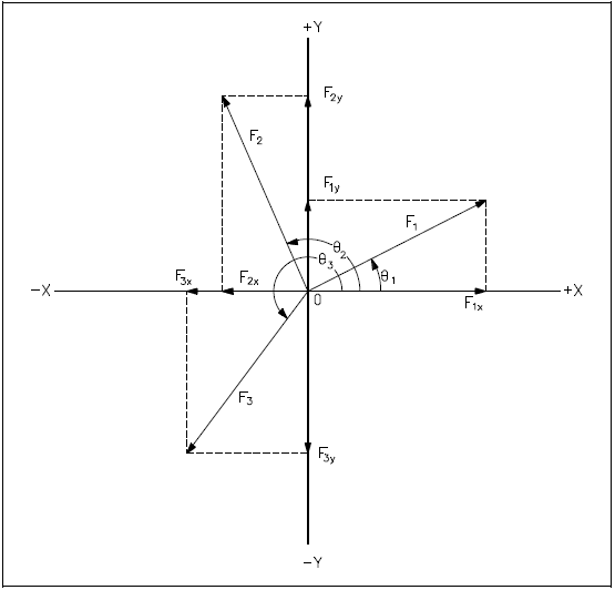
Draw x and y coordinates and the three forces from the point of origin or the center of the object, as shown in Figure 26. Component vectors and angles have been added to the drawing to aid in the discussion. |
||||||||||||||||
| Step 2: |
Resolve each vector into its rectangular components.
|
||||||||||||||||
| Step 3: |
Sum the x and y components. FRx = ΣFx = F1x + F2x + F3x FRy = ΣFy = F1y + F2y + F3y Where "Σ" means summation |
||||||||||||||||
| Step 4: |
Calculate the magnitude of FR. $$ F_R = \sqrt{ F_{Rx}^2 + F_{Ry}^2 } $$ |
||||||||||||||||
| Step 5: |
Calculate the angle of displacement. $$ \tan \theta = {F_{Ry} \over F_{Rx}} $$ $$ \theta = \tan^{-1} {F_{Ry} \over F_{Rx}} $$ |
| Example: | Given three forces acting on an object, determine the magnitude and direction of the resultant force FR. |
F1 = 90 lbf at 39°
F2 = 50 lbf at 120°
F3 = 125 lbf at 250°
| Step 1: |
First draw x and y coordinate axes on a sheet of paper. Then, draw F1, F2, and F3 from the point of origin. It is not necessary to be totally accurate in placing the vectors in the drawing. The approximate location in the right quadrant is all that is necessary. Label the drawing as in the model (Figure 26). |
||||||||||||||||||||
| Step 2: |
Resolve each vector into its rectangular coordinates.
|
||||||||||||||||||||
| Step 3: |
Sum the x and y components. FRx = F1x + F2x + F3x FRx = 69.9 lbf + (−25 lbf) + (−42.8 lbf) FRx = 2.1 lbf FRy = F1y + F2y + F3y FRy = 56.6 lbf + 43.3 lbf + (−117.5 lbf) FRy = −17.6 lbf |
||||||||||||||||||||
| Step 4: |
Calculate the magnitude of FR. $$ F_R = \sqrt{ F_{Rx}^2 + F_{Ry}^2 } $$ $$ F_R = \sqrt{ (2.1)^2 + (-17.6)^2 } $$ $$ F_R = \sqrt{ 314.2 } $$ FR = 17.7 lbf |
||||||||||||||||||||
| Step 5: |
Calculate the angle of displacement. tanθ = FRy/FRx tanθ = −17.6/2.1 tanθ = −8.381 θ = tan-1(−8.381) θ = −83.2° |
Therefore, FR = 17.7 lbf at −83.2° or 276.8°
Note: A negative angle means a clockwise rotation from the zero axis.
It is left to the student to try the previous example using the other methods of vector addition described in earlier chapters.
