Chapter 11: Pneumatics
This page provides the chapter on pneumatics from the U.S. Navy's fluid power training course, NAVEDTRA 14105A, "Fluid Power," Naval Education and Training Professional Development and Technology Center, July 2015.
Other related chapters from the Navy's fluid power training course can be seen to the right.
Pneumatics
The word pneumatics is a derivative of the Greek word pneuma, which means air, wind, or breath. It can be defined as that branch of engineering science that pertains to gaseous pressure and flow. As used in this manual, pneumatics is the portion of fluid power in which compressed air, or other gas, is used to transmit and control power to actuating mechanisms.
This chapter discusses the basic principles of pneumatics. It discusses the characteristics of gases and compares them with those of liquids. It explains factors which affect the properties of gases, identifies and explains the gas laws, and identifies gases commonly used in pneumatics and their pressure ranges. It also discusses hazards of pneumatic gases, methods of controlling contamination, and safety precautions associated with compressed gases.
Learning Objectives
When you have completed this chapter, you will be able to do the following:
- Recognize the pressure characteristics of gases and liquids.
- Recognize the common temperature scales.
- Recognize various theories, laws, and properties of gases.
- Recognize characteristics of gases used in pneumatic systems.
- Recognize the color codes of compressed gas cylinders.
- Identify safety precautions for handling compressed gas.
Characteristics of Gases
Gas is one of the three states of matter. It has characteristics similar to those of liquids in that it has no definite shape but conforms to the shape of its container and readily transmits pressure.
Gases differ from liquids in that they have no definite volume. That is, regardless of the size or shape of the containing vessel, a gas will completely fill it. Gases are highly compressible, while liquids are only slightly so. Also, gases are lighter than equal volumes of liquids, making gases less dense than liquids.
Density
Density, as defined in chapter 2, is the weight per unit volume of a substance. Since gases do not have a specific volume, the gas depends on the size of the container holding it to calculate the volume. The number of molecules and the weight of the molecules from the periodic table are calculated for the weight of the gas. To calculate the density of the gas, the weight of the gas is divided by the volume of the gas. The formula for density will be discussed later in the chapter.
Temperature and Pressure Relationship
Early experiments were conducted concerning the behavior of air and similar gases. These experiments were conducted by scientists such as Boyle and Charles. Italian scientist, Amedeo Avogadro, discovered a relationship between pressure, temperature, volume, and the amount of gas in a specified container.
The results of their experiments indicated that the gases' behavior follows the law known as the ideal-gas law. It states as follows: For a given weight of any gas, the product of the absolute pressure and the volume occupied, divided by the absolute temperature, is constant. In the equation form, it is expressed as follows:
For 1 pound of gas,
also,
| PV = nRT | and | Pv = RT |
where:
| P | = | absolute pressure |
| V | = | total volume |
| v | = | specific volume |
| n | = | amount of gas (number of molecules) |
| T | = | absolute temperature |
| R | = | gas constant |
The specific volume (v) is expressed in cubic feet per pound.
For any weight of a gas this equation may be modified as follows:
| W | = | weight of the gas in pounds |
| V | = | volume of W pounds of the gas in cubic feet |
The volume of 1 pound would then be V/W. If we substitute V/W for v in equation 11-2, it then becomes PV/W = RT, or
Solving equation 11-4 for pressure,
In equation 11-4, W/V represents density. (Notice that this equation is the inverse of the specific volume.) We can now say that pressure is equal to the density of the gas times the gas constant times the absolute temperature of the gas. The gas constant varies for different gases. From this equation we can show how density varies with changes in pressure and temperature. Decreasing the volume, with the weight of the gas and the temperature held constant, causes the pressure to increase.
During the compression of the gas, the temperature will actually increase; however, the explanation for this is beyond the scope of this text.
Also, since density equals W/V, a decrease in volume with the weight held constant will cause density to increase.
Temperature
As indicated previously, temperature is a dominant factor affecting the physical properties of gases. It is of particular concern in calculating changes in the states of gases.
Three temperature scales are used extensively in gas calculations. They are the Celsius (C), the Fahrenheit (F), and the Kelvin (K) scales. The Celsius (or centigrade) scale is constructed by identifying the freezing and boiling points of water, under standard conditions, as fixed points of 0 and 100 degrees, respectively, with 100 equal divisions between. The Fahrenheit scale identifies 32 degrees as the freezing point of water and 212 degrees as the boiling point, and has 180 equal divisions between. The Kelvin scale has its zero point equal to −273 °C, or −460 °F.
Absolute zero, one of the fundamental constants of physics, is commonly used in the study of gases. It is usually expressed in terms of the Celsius scale. If the heat energy of a gas sample could be progressively reduced, some temperature should be reached at which the motion of the molecules would cease entirely. If accurately determined, this temperature could then be taken as a natural reference, or as a true absolute zero value.
Experiments with hydrogen indicated that if a gas were cooled to −273.16 °C (−273 °C for most calculations), all molecular motion would cease and no additional heat could be extracted. Since this is the coldest temperature to which an ideal gas can be cooled, it is considered to be absolute zero. Absolute zero may be expressed as 0 °K, −273 °C, or −459.69 °F (−460 °F for most calculations).
When you work with temperatures, always be sure which system of measurement is being used and how to convert from one to another. The conversion formulas are shown in Figure 11-1. For purposes of calculations, the Rankine (R) scale illustrated in Figure 11-1 is commonly used to convert Fahrenheit to absolute temperature. For Fahrenheit readings above zero, 460 degrees is added. Thus, 72 °F equals 460 degrees plus 72 degrees, or 532 degrees absolute (532 °R). If the Fahrenheit reading is below zero, it is subtracted from 460 degrees. Thus, −40 °F equals 460 degrees minus 40 degrees, or 420 degrees absolute (420 °R).
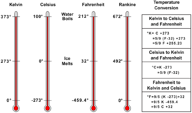
The Kelvin and Celsius scales are used internationally in scientific measurements; therefore, some technical manuals may use these scales in directions and operating instructions. The Fahrenheit scale is commonly used in the United States; therefore, it is used in most areas of this manual.
Pressure
We defined pressure in chapter 2 as force per unit area. Remember, liquids exert pressure on all surfaces with which they come in contact. Gases, because of their ability to completely fill containers, exert pressure on all sides of a container.
In practice, we may be interested in either of two pressure readings. We may desire either the gauge pressure or the absolute pressure.
Absolute pressure is measured relative to the absolute zero pressure — the pressure that would occur at absolute vacuum. All calculation involving the gas laws requires pressure (and temperature) to be in absolute units. Gauge Pressure is often called the gauge pressure (a gauge is often used to measure the pressure difference between a system and the surrounding atmosphere). Therefore Gauge Pressure is measured from atmospheric, and absolute is measured from 0 (as all absolute scales are measured from). They both use the same scale for measuring. Standard atmosphere at sea level is 14.7 pounds per square inch of pressure absolute and 0 pressure gauge. If you have 100 pounds per square inch (psi) gauge pressure, you have 14.7 + 100 psi absolute. Atmospheric Pressure is pressure in the surrounding air at — or "close" to — the surface of the earth. The atmospheric pressure varies with temperature and altitude above sea level.
Compressibility and Expansion of Gases
Gases can be readily compressed and are assumed to be perfectly elastic. This combination of properties gives a gas the ability to yield to a force and return promptly to its original condition when the force is removed. These are the properties of air that are used in pneumatic tires, tennis balls, and other deformable objects whose shapes are maintained by compressed air.
Kinetic Theory of Gases
In an attempt to explain the compressibility of gases, Bernoulli proposed the hypothesis that is accepted as the kinetic theory of gases. According to this theory, the pressure exerted by a gas on the walls of a closed container is caused by continual bombardment of the walls by molecules of the gas.
Consider the container shown in Figure 11-2 as containing a gas. At any given time, some molecules are moving in one direction, some are traveling in other directions; some are traveling fast, some slow, and some may even be in a state of rest. The average effect of the molecules bombarding each container wall corresponds to the pressure of the gas.

As more gas is pumped into the container, more molecules are available to bombard the walls; thus the pressure in the container increases.
The gas pressure in a container can also be increased by increasing the speed with which the molecules hit the walls. If the temperature of the gas is raised, the molecules move faster, causing an increase in pressure. This pressure increase can be shown by considering the automobile tire. When you take a long drive on a hot day, the pressure in the tires increases and a tire which appeared to be somewhat "soft" in the cool morning temperature may appear normal at a higher midday temperature.
Boyle's Law
When the automobile tire is initially inflated, air that normally occupies a specific volume is compressed into a smaller volume inside the tire. This increases the pressure on the inside of the tire.
Charles Boyle, an English scientist, was among the first to experiment with the pressure-volume relationship of gas. During an experiment, when he compressed a volume of air he found that the volume decreased as the pressure increased, and by doubling the force exerted on the air he could decrease the volume of the air by half (Figure 11-3). Recall from the example of the automobile tire that changes in temperature of a gas also change the pressure and volume. Therefore, the experiment must be performed at a constant temperature. The relationship between pressure and volume is known as Boyle's law. It states: When the temperature of a gas is kept constant, the volume of an enclosed gas varies inversely with its pressure.
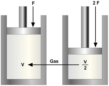
In equation form, this relationship may be expressed as
where V1 and P1 are the initial volume and pressure, and V2 and P2 are the final volume and pressure (P1 and P2 are absolute pressures).
Example of Boyle's law: 4 cubic feet of nitrogen are under a pressure of 100 psi (gauge). The nitrogen is allowed to expand to a volume of 6 cubic feet. What is the new gauge pressure? Remember to convert gauge pressure to absolute pressure by adding 14.7.
Using equation 11-6, V1P1 = V2P2, where V1 is 4 ft 3, V2 is 6 ft, and P1 is 100 psig:
Solution:
V1P1 = V2P2
P2 = V1P1/V2
Substituting:
P2 = 4 (100 + 14.7) / 6
= 76.47 psia
Converting absolute pressure to gauge pressure:
Charles's Law
Boyle's law assumes conditions of constant temperature. In actual situations this constant temperature is rarely the case. Temperature changes continually and affects the volume of a given mass of gas.
Jacques Charles, a French physicist, provided much of the foundation for the modern kinetic theory of gases. Through experiments, he found that all gases expand and contract proportionally to the change in the absolute temperature, providing the pressure remains constant. The relationship between volume and temperature is known as Charles's law. It states: The volume of a gas is proportional to its absolute temperature, if constant pressure is maintained. In equation form, this relationship may be expressed as
Where V1 and V2 are the original and final volumes, and T1 and T2 are the original and final absolute temperatures.
Since an increase in the temperature of a gas causes it to expand if the pressure is kept constant, it is reasonable to expect that if a given sample is heated within a closed container and its volume remains constant, the pressure of the gas will increase. Experiments have proven this expectation to be true. In equation form, this becomes
or
$$ { P_1 \over P_2 } = { T_1 \over T_2 } $$This equation states that for a constant volume, the absolute pressure of a gas varies directly with the absolute temperature.
Example: A cylinder of gas under a pressure of 1,800 psig at 70 °F is left out in the sun in the tropics and heats up to a temperature of 130 °F. What is the new pressure within the cylinder? (Remember that both pressure and temperature must be converted to absolute pressure and absolute temperature.)
Using equation 11-7, P1T2 = P2T1, when P1 is 1,800 psig, T1 is 70 °F, and T2 is 130 °F:
Solution:
P1T2 = P2T1
P2 = P1T2/T1
Substituting:
Converting absolute pressure to gauge pressure:
General Gas Law
We have learned that Boyle's law pertains to situations in which the temperature remains constant (Figure 11-4), and that Charles's law pertains to situations in which pressure remains constant (Figure 11-4). It is usually not possible to control pressure or temperature in tanks or bottles of gas subject to the weather and shipboard demands. Boyle's and Charles's laws are combined to form the general gas law. This law states: The product of the initial pressure, initial volume, and new temperature (absolute scale) of an enclosed gas is equal to the product of the new pressure, new volume, and initial temperature. It is a mathematical statement that allows many gas problems to be solved by using the principles of Boyle's law and/or Charles's law. The equation is expressed as
or
$$ { P_1 V_1 \over T_1 } = { P_2 V_2 \over T_2 } $$(P and T represent absolute pressure and absolute temperature, respectively.)
You can see by examining Figure 11-4 that the three equations are special cases of the general equation. Thus, if the temperature remains constant, T1 equals T2 and both can be eliminated from the general formula, which then reduces to the form shown Figure 11-4, view A. When the volume remains constant, V1 equals V2, thereby reducing the general equation to the form given shown Figure 11-4, view B. Similarly, P1 is equated to P2 for constant pressure, and the equation then takes the form given shown Figure 11-4, view C.
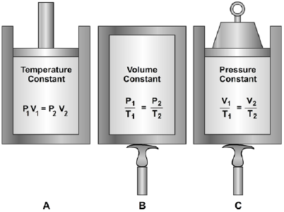
The general gas law applies with exactness only to "ideal" gases in which the molecules are assumed to be perfectly elastic. However, it describes the behavior of actual gases with sufficient accuracy for most practical purposes.
Two examples of the general equation follow:
1. Two cubic feet of a gas at 75 psig and 80 °F are compressed to a volume of 1 cubic foot and then heated to a temperature of 300 °F. What is the new gauge pressure?
Using equation 11-8, P1V1T2 = P2V2T1, where V1 is 2 ft3, P1 is 75 psig, T1 is 80 °F, V2 is 1 ft3, and T2 is 300 °F:
Solution:
or
Substituting:
Converting absolute pressure to gauge pressure:
252.5 − 14.7 = 237.8 psig
2. Four cubic feet of a gas at 75 psig and 80 °F are compressed to 237.8 psig and heated to a temperature of 300 °F. What is the volume of the gas resulting from these changes? Using equation 11-8, P1V1T2 = P2V2T1, where V1 is 4 ft3, P2 is 75 psig, T1 is 80 °F, P1 is 237.8 psig, and T2 is 300 °F:
Solution:
or
Substituting:
Pneumatic Gases
Many factors are considered in determining whether to use hydraulics or pneumatics as a power source in a fluid power system. Once it is determined that pneumatics will be used as the source of power, some of the same factors are considered in selecting the pneumatic gas.
Qualities
The ideal fluid medium for a pneumatic system is a readily available gas that is nonpoisonous (nontoxic), chemically stable, free from any acids that cause corrosion of system components, and nonflammable. It also will not support combustion of other elements.
Gases that have these desired qualities may not have the required lubricating power. Therefore, lubrication of the components of some pneumatic systems must be arranged by other means. For example, some air compressors are provided with a lubricating system, some components are lubricated upon installation, or, in some cases, lubrication is introduced into the air supply line.
Two gases meeting these qualities and most commonly used in pneumatic systems are compressed air and nitrogen.
Compressed Air
Compressed air is a mixture of all gases contained in the atmosphere. In this manual, compressed air is referred to as a gas when it is used as a fluid medium.
The unlimited supply of air and the ease of compression make compressed air the most widely used fluid for pneumatic systems. Although moisture and solid particles must be removed from the air, it does not require the extensive distillation or separation process required in the production of other gases.
Compressed air has most of the desired properties and characteristics of a gas for pneumatic systems. It is nonpoisonous and nonflammable but does contain oxygen, which supports combustion. One of the most undesirable qualities of compressed air as a fluid medium for pneumatic systems is moisture content. The atmosphere contains varying amounts of moisture in vapor form. Changes in the temperature of compressed air will cause condensation of moisture in the pneumatic system. This condensed moisture can be very harmful to the system, as it increases corrosion, dilutes lubricants, and may freeze in lines and components during cold weather. Moisture separators and air driers (dehydrators) are installed in the compressed air lines to minimize or eliminate moisture in systems where moisture would deteriorate system performance.
The supply of compressed air at the required volume and pressure is provided by an air compressor. In most systems, the compressor is part of the system with distribution lines leading from the compressor to the devices to be operated. In these systems, a receiver is installed in-line between the compressor and the device to be operated to help eliminate pulsations in the compressor discharge line, to act as a storage tank during intervals when the demand for air exceeds the compressor's capacity, and to enable the compressor to shut down during periods of light load. Other systems receive their supply from cylinders, which must be filled at a centrally located air compressor and then connected to the system.
Compressed air systems are categorized by their operating pressures as follows: high-pressure (HP) air, medium-pressure (MP) air, and low-pressure (LP) air.
High-Pressure (HP) Air Systems
HP air systems provide compressed air at a nominal operating pressure of 3,000 psi or 5,000 psi and are installed whenever pressure in excess of 1,000 psi is required. HP compressed air plants support functions that require high pressures and high flow rates of compressed air by the addition of HP storage flasks to the system. An example of such a system is one that provides air for starting diesel and gas turbine engines. Reduction in pressure, if required, is done by using specially designed pressure-reducing stations.
Medium-Pressure (MP) Air Systems
MP air systems provide compressed air at a nominal operating pressure of 151 psi to 1,000 psi. These pressures are provided either by an MP air compressor or by the HP air system supplying air through an air bank and pressure-reducing stations.
Low-Pressure (LP) Air Systems
LP air systems provide compressed air at a nominal operating pressure of 150 psi and below. The LP air system is supplied with LP air by LP air compressors or by the HP air system supplying air through an air bank and pressure-reducing stations. LP air is the most extensive and varied air system used in the Navy.
In addition to being used for various pneumatic applications, LP and HP compressed air are used in the production of nitrogen.
Nitrogen
For all practical purposes, nitrogen is considered to be an inert gas. It is nonflammable, does not form explosive mixtures with air or oxygen, and does not cause rust or decay. Due to these qualities, its use is preferred over compressed air in many pneumatic systems, especially aircraft and missile systems, and wherever an inert gas blanket is required.
Nitrogen is obtained by the fractional distillation of air. Oxygen/nitrogen-producing plants expand compressed air until its temperature decreases to −196 °C (−320 °F), the boiling point of nitrogen at atmospheric pressure. The liquid nitrogen is then directed to a storage tank. A liquid nitrogen pump pumps the low-pressure liquid nitrogen from the storage tank and discharges it as a high-pressure (5,000 psi) liquid to the vaporizer where it is converted to a gas at 5,000 psi. Oxygen/nitrogen-producing plants are located at many naval installations and on submarine tenders and aircraft carriers.
Contamination Control
As in hydraulic systems, fluid contamination is also a leading cause of malfunctions in pneumatic systems. In addition to the solid particles of foreign matter that find a way to enter the system, there is also the problem of moisture. Most systems are equipped with one or more devices to remove this contamination. These include filters, water separators, air dehydrators, and chemical driers. In addition, most systems contain drain valves at critical low points in the system. These valves are opened periodically to allow the escaping gas to purge a large percentage of the contaminants, both solids and moisture, from the system. In some systems these valves are opened and closed automatically, while in others they must be operated manually.
Complete purging is done by removing lines from various components throughout the system and then attempting to pressurize the system, causing a high rate of airflow through the system. The airflow will cause the foreign matter to be dislodged and blown from the system.
If an excessive amount of foreign matter, particularly oil, is blown from any one system, the lines and components should be removed and cleaned or replaced.
In addition to monitoring the devices installed to remove contamination, it is your responsibility as a maintenance person or supervisor to control the contamination. You can control contamination by using the following maintenance practices:
- Keep all tools and the work area in a clean, dirt-free condition.
- Cap or plug all lines and fittings immediately after disconnecting them.
- Replace all packing and gaskets during assembly procedures.
- Connect all parts with care to avoid stripping metal slivers from threaded areas. Install and torque all fittings and lines according to applicable technical instructions.
- Complete preventive maintenance as specified by maintenance requirements cards (MRCs).
Also, you must take care to ensure that the proper cylinders are connected to systems being supplied from cylinders.
Cylinders for compressed air are painted black. Cylinders containing oil-pumped air have two green stripes painted around the top of the cylinder, while cylinders containing water-pumped air have one green stripe. Oil-pumped air indicates that the air or nitrogen is compressed by an oil-lubricated compressor. Air or nitrogen compressed by a water-lubricated (or non-lubricated) compressor is referred to as water pumped. Oil-pumped nitrogen can be very dangerous in certain situations. For example, nitrogen is commonly used to purge oxygen systems. Oxygen will not burn, but it supports and accelerates combustion and will cause oil to burn easily and with great intensity. Therefore, oil-pumped nitrogen must never be used to purge oxygen systems. When the small amount of oil remaining in the nitrogen comes in contact with the oxygen, an explosion may result. In all situations, use only the gas specified by the manufacturer or recommended by the Navy. Nitrogen cylinders are painted gray. One black stripe identifies cylinders for oil-pumped nitrogen, and two black stripes identify cylinders for water-pumped nitrogen. In addition to these color codes, the exact identification of the contents is printed in two locations diametrically opposite one another along the longitudinal axis of the cylinder. For compressed air and nitrogen cylinders, the lettering is white.
Potential Hazards
All compressed gases are hazardous. Compressed air and nitrogen are neither poisonous nor flammable, but should not be handled carelessly. Some pneumatic systems operate at pressures exceeding 3,000 psi. Lines and fittings have exploded, injuring personnel and property. Literally thousands of careless workers have blown dust or harmful particles into their eyes by the careless handling of compressed air outlets.
Nitrogen gas will not support life, and when it is released in a confined space, it will cause asphyxia (the loss of consciousness as a result of too little oxygen and too much carbon dioxide in the blood). Although compressed air and nitrogen seem so safe in comparison with other gases, do not let overconfidence lead to personal injury.
Safety Precautions
To minimize personal injury and equipment damage when using compressed gases, observe all practical operating safety precautions, including the following:
- Do not use compressed air to clean parts of your body or clothing, or to perform general space cleanup in lieu of vacuuming or sweeping.
- Never attempt to stop or repair a leak while the leaking portion is still under pressure. Always isolate, repressurize, and danger tag out the portion of the system to be repaired. For pressures of 1,000 psi or greater, double valve protection is required to prevent injury if one of the valves should fail.
- Avoid the application of heat to the air piping system or components, and avoid striking a sharp or heavy blow on any pressurized part of the piping system.
- Avoid rapid operation of manual valves. The heat of compression caused by a sudden high-pressure flow into an empty line or vessel can cause an explosion if oil is present. Valves should be slowly cracked open until airflow is noted and should be kept in this position until pressures on both sides of the valve have equalized. The rate of pressure rise should be kept under 200 psi per second, if possible. Valves may then be opened fully.
- Do not discharge large quantities of nitrogen into closed compartments unless adequate ventilation is provided.
- Do not subject compressed gas cylinders to temperatures greater than 130 °F.
Remember, any pressurized system can be hazardous to your health if it is not maintained and operated carefully and safely.
PDH Classroom offers a continuing education course based on this pneumatics reference page. This course can be used to fulfill PDH credit requirements for maintaining your PE license.
Now that you've read this reference page, earn credit for it!
