Chapter 5: Fluid Lines and Fittings
This page provides the chapter on hydraulic lines and fittings from the U.S. Navy's fluid power training course, NAVEDTRA 14105A, "Fluid Power," Naval Education and Training Professional Development and Technology Center, July 2015.
Other related chapters from the Navy's fluid power training course can be seen to the right.
Fluid Lines and Fittings
The control and application of fluid power would be impossible without suitable means of transferring the fluid between the reservoir, the power source, and the points of application. Fluid lines are used to transfer the fluid, and fittings are used to connect the lines to the power source and the points of application.
Learning Objectives
When you have completed this chapter, you will be able to do the following:
- Identify the basic requirements for fluid power system lines.
- Recognize pertinent facts concerning identification, and sizing of pipe and tubing.
- Recognize the uses and construction features of pipe and tubing.
- Recognize the characteristics, uses, and construction features of flexible hose.
- Identify the installation procedures for flexible hose.
- Recognize the uses and construction features of fluid power system connectors.
- Identify the operational characteristics and functions of fluid power system and connectors.
- Recognize the precautionary measures associated with fluid power system connectors.
Types of Lines
The three types of lines used in fluid power systems are pipe (rigid), tubing (semirigid), and hose (flexible). A number of factors are considered when the type of line is selected for a particular fluid system. These factors include the type of fluid, the required system pressure, and the location of the system. For example, heavy pipe might be used for a large stationary fluid power system, but comparatively lightweight tubing must be used in aircraft and missile systems because weight and space are critical factors. Flexible hose is required in installations where units must be free to move relative to each other.
Pipes and Tubing
There are three important dimensions of any tubular product — outside diameter (OD), inside diameter (ID), and wall thickness. Sizes of pipe are listed by the nominal (or approximate) ID and the wall thickness. Sizes of tubing are listed by the actual OD and the wall thickness.
Selection of Pipes and Tubing
The material, ID, and wall thickness are the three primary considerations in the selection of lines for a particular fluid power system.
The ID of a line is important, since it determines how much fluid can pass through the line in a given time period (rate of flow) without loss of power due to excessive friction and heat. The velocity of a given flow is less through a large opening than through a small opening. If the ID of the line is too small for the amount of flow, excessive turbulence and friction heat cause unnecessary power loss and overheated fluid.
Sizing of Pipes and Tubing
Pipes are available in three different weights: standard (STD) or Schedule 40, extra strong (XS) or Schedule 80, and double extra strong (XXS). The schedule numbers range from 10 to 160 and cover 10 distinct sets of wall thickness (Table 5-1). Schedule 160 wall thickness is slightly thinner than double extra strong.
| Nominal Size | Pipe OD | Inside Diameter [inch] | |||||||||
|---|---|---|---|---|---|---|---|---|---|---|---|
| Sched. 10 | Sched. 20 | Sched. 30 | Sched. 40 | Sched. 60 | Sched. 80 | Sched. 100 | Sched. 120 | Sched. 140 | Sched. 160 | ||
| 1/8 | 0.405 | 0.269 | 0.215 | ||||||||
| 1/4 | 0.540 | 0.364 | 0.302 | ||||||||
| 3/8 | 0.675 | 0.493 | 0.423 | ||||||||
| 1/2 | 0.840 | 0.622 | 0.546 | 0.466 | |||||||
| 3/4 | 1.050 | 0.824 | 0.742 | 0.614 | |||||||
| 1 | 1.315 | 1.049 | 0.957 | 0.815 | |||||||
| 1 1/4 | 1.660 | 1.380 | 1.278 | 1.160 | |||||||
| 1 1/2 | 1.900 | 1.610 | 1.500 | 1.388 | |||||||
| 2 | 2.375 | 2.067 | 1.939 | 1.689 | |||||||
As mentioned earlier, the size of pipes is determined by the nominal (approximate) ID. For example, the ID for a 1/4-inch Schedule 40 pipe is 0.364 inch, and the ID for a 1/2-inch Schedule 40 pipe is 0.622 inch.
It is important to note that the IDs of all pipes of the same nominal size are not equal. This difference is because the OD remains constant and the wall thickness increases as the schedule number increases. For example, a nominal size 1-inch Schedule 40 pipe has a 1.049 ID. The same size Schedule 80 pipe has a 0.957 ID, while Schedule 160 pipe has a 0.815 ID. In each case the OD is 1.315 (Table 5-1) and the wall thicknesses are 0.133 [(1.315 - 1.049) / 2], 0.179 [(1.315 - 0.957) / 2], and 0.250 [(1.315 - 0.815) / 2] respectively. Note that the difference between the OD and ID includes two wall thicknesses and must be divided by 2 to obtain the wall thickness.
Tubing differs from pipe in its size classification. Tubing is designated by its actual OD (Table 5-2). Thus, 5/8-inch tubing has an OD of 5/8 inch. As indicated in the table, tubing is available in a variety of wall thicknesses. The diameter of tubing is often measured and indicated in 16ths of an inch. Thus, No. 6 tubing is 6/16 or 3/8 inch, No. 8 tubing is 8/16 or 1/2 inch, and so forth.
| Tube OD | Wall Thickness | Tube ID |
|---|---|---|
| 1/8 | 0.028 | 0.069 |
| 0.032 | 0.061 | |
| 0.035 | 0.055 | |
| 3/16 | 0.032 | 0.1235 |
| 0.035 | 0.1175 | |
| 1/4 | 0.035 | 0.180 |
| 0.042 | 0.166 | |
| 0.049 | 0.152 | |
| 0.058 | 0.134 | |
| 0.065 | 0.120 | |
| 5/16 | 0.035 | 0.2425 |
| 0.042 | 0.2285 | |
| 0.049 | 0.2145 | |
| 0.058 | 0.1965 | |
| 0.065 | 0.1825 | |
| 3/8 | 0.035 | 0.305 |
| 0.042 | 0.291 | |
| 0.049 | 0.277 | |
| 0.058 | 0.259 | |
| 0.065 | 0.245 | |
| 1/2 | 0.035 | 0.430 |
| 0.042 | 0.416 | |
| 0.049 | 0.402 | |
| 0.058 | 0.384 | |
| 0.065 | 0.370 | |
| 0.072 | 0.358 | |
| 0.083 | 0.334 | |
| 0.095 | 0.310 | |
| 5/8 | 0.035 | 0.555 |
| 0.042 | 0.541 | |
| 0.049 | 0.527 | |
| 0.058 | 0.509 | |
| 0.065 | 0.495 | |
| 0.072 | 0.481 | |
| 0.083 | 0.459 | |
| 0.095 | 0.435 | |
| 3/4 | 0.049 | 0.652 |
| 0.058 | 0.634 | |
| 0.065 | 0.620 | |
| 0.072 | 0.606 | |
| 0.083 | 0.584 | |
| 0.095 | 0.560 | |
| 0.109 | 0.532 |
| Tube OD | Wall Thickness | Tube ID |
|---|---|---|
| 7/8 | 0.049 | 0.777 |
| 0.058 | 0.759 | |
| 0.065 | 0.745 | |
| 0.072 | 0.731 | |
| 0.083 | 0.709 | |
| 0.095 | 0.685 | |
| 0.109 | 0.657 | |
| 1 | 0.049 | 0.902 |
| 0.058 | 0.884 | |
| 0.065 | 0.870 | |
| 0.072 | 0.856 | |
| 0.083 | 0.834 | |
| 0.095 | 0.810 | |
| 0.109 | 0.782 | |
| 0.120 | 0.760 | |
| 1 1/4 | 0.049 | 1.152 |
| 0.058 | 1.134 | |
| 0.065 | 1.120 | |
| 0.072 | 1.106 | |
| 0.083 | 1.084 | |
| 0.095 | 1.060 | |
| 0.109 | 1.032 | |
| 0.120 | 1.010 | |
| 1 1/2 | 0.065 | 1.370 |
| 0.072 | 1.356 | |
| 0.083 | 1.334 | |
| 0.095 | 1.310 | |
| 0.109 | 1.282 | |
| 0.120 | 1.260 | |
| 0.134 | 1.232 | |
| 1 3/4 | 0.065 | 1.620 |
| 0.072 | 1.606 | |
| 0.083 | 1.584 | |
| 0.095 | 1.560 | |
| 0.109 | 1.532 | |
| 0.120 | 1.510 | |
| 0.134 | 1.482 | |
| 2 | 0.065 | 1.870 |
| 0.072 | 1.856 | |
| 0.083 | 1.834 | |
| 0.095 | 1.810 | |
| 0.109 | 1.782 | |
| 0.120 | 1.760 | |
| 0.134 | 1.732 |
The wall thickness, material used, and ID determine the bursting pressure of a line or fitting. The greater the wall thickness in relation to the ID and the stronger the metal, the higher the bursting pressure. However, the greater the ID for a given wall thickness, the lower the bursting pressure, because force is the product of area and pressure.
Materials
The pipe and tubing used in fluid power systems are commonly made from steel, copper, brass, aluminum, and stainless steel. Each of these metals has its own distinct advantages or disadvantages in certain applications.
Steel pipe and tubing are relatively inexpensive and are used in many hydraulic and pneumatic systems. Steel is used because of its strength, suitability for bending and flanging, and adaptability to high pressures and temperatures. Its chief disadvantage is its comparatively low resistance to corrosion.
Copper pipe and tubing are sometimes used for fluid power lines. Copper has high resistance to corrosion and is easily drawn or bent. However, it is unsatisfactory for high temperatures and has a tendency to harden and break due to stress and vibration.
Aluminum has many of the characteristics and qualities required for fluid power lines. It has high resistance to corrosion and is easily drawn or bent. In addition, it has the outstanding characteristic of light weight. Since weight elimination is a vital factor in the design of aircraft, aluminum alloy tubing is used in the majority of aircraft fluid power systems.
Stainless steel tubing is used in certain areas of many aircraft fluid power systems. As a general rule, exposed lines and lines subject to abrasion or intense heat are made of stainless steel.
An improperly piped system can lead to serious power loss and possible harmful fluid contamination. Therefore, in maintenance and repair of fluid power system lines, the basic design requirements must be kept in mind. Two primary requirements are as follows:
- The lines must have the correct ID to provide the required volume and velocity of flow with the least amount of turbulence during all demands on the system.
- The lines must be made of the proper material and have the wall thickness to provide sufficient strength to both contain the fluid at the required pressure and withstand the surges of pressure that may develop in the system.
Preparation of Pipes and Tubing
Fluid power systems are designed as compactly as possible, to keep the connecting lines short. Every section of line should be anchored securely in one or more places so that neither the weight of the line nor the effects of vibration are carried on the joints. The aim is to minimize stress throughout the system.
Lines should normally be kept as short and free of bends as possible. However, tubing should not be assembled in a straight line, because a bend tends to eliminate strain by absorbing vibration and also compensates for thermal expansion and contraction. Bends are preferred to elbows, because bends cause less of a power loss. A few of the correct and incorrect methods of installing tubing are illustrated in Figure 5-1.

Bends are described by their radius measurements. The ideal bend radius is 2 1/2 to 3 times the ID, as shown in Figure 5-2. For example, if the ID of a line is 2 inches, the radius of the bend should be between 5 and 6 inches.
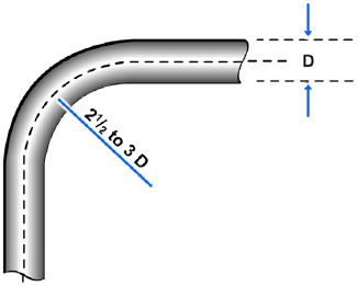
While friction increases significantly for sharper curves than this, it also tends to increase up to a certain point for gentler curves. The increases in friction in a bend with a radius of more than 3 pipe diameters results from increased turbulence near the outside edges of the flow. Particles of fluid must travel a longer distance in making the change in direction. When the radius of the bend is less than 2 1/2 pipe diameters, the increased pressure loss is due to the abrupt change in the direction of flow, especially for particles near the inside edge of the flow.
At times, new tubing may need to be fabricated to replace damaged or failed lines. Fabrication of tubing consists of four basic operations: cutting, deburring, bending, and joint preparation.
Tube Cutting and Deburring
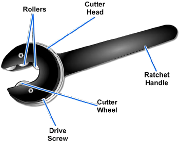
The objective of cutting tubing is to produce a square end that is free from burrs. Tubing may be cut using a tube cutter (Figure 5-3), or a chipless cutter (Figure 5-4).
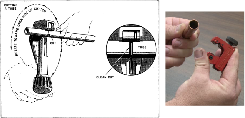
Tubing should be cut with a tubing cutter, when available. The tubing should be marked where it is to be cut and the cutter should be installed so the cutter wheel is over the mark and the cutting wheel can be seen from the top view of the pipe, as shown in Figure 5-3. The adjustment wheel or handle should be turned clockwise to force the cutter wheel against the copper. The cutter should be revolved around the tubing and turn the adjustment wheel 1/4 turn per rotation until the copper is cut through and separates.
Tubing may be cut with a hacksaw, although a tubing cutter is preferable. It is important to be careful to cut the tubing square if it is to be flared. A fine-toothed hacksaw blade, with 32 teeth per inch, should be used when cutting copper.
The following steps should be taken when using a chipless cutter:
- Select the chipless cutter according to tubing size.
- Rotate the cutter head to accept the tubing in the cutting position. Check that the cutter ratchet is operating freely and that the cutter wheel is clear of the cutter head opening (Figure 5-4).
- Center the tubing on two rollers and the cutting blade.
- Use the hex key provided to turn the drive screw in until the cutter touches the tube.
- Tighten the drive screw 1/8 to 1/4 turn. Do not overtighten the drive screw. Overtightening can damage soft tubing or cause excessive wear or breakage of the cutter wheel in hard tubing.
- Swing the ratchet handle back and forth through the available clearance until there is a noticeable ease of rotation. Avoid putting side force on the cutter handle. Side force will cause the cutter wheel to break.
- Tighten the drive screw an additional 1/8 to 1/4 turn and swing the ratchet handle back and forth, retightening the drive screw as needed until the cut is completed. The completed cut should be 1/2 degree square to the tube centerline.
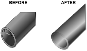
After the tubing is cut, all burrs and sharp edges should be removed from inside and outside of the tube (Figure 5-5) with deburring tools. The tubing should be cleaned to make sure there are no foreign particles remaining. A convenient method for cutting tubing with a hacksaw is to place the tube in a flaring block and clamp the block in a vice. After cutting the tubing with a hacksaw, all saw marks should be removed by filing.
Tube Bending
The objective in tube bending is to obtain a smooth bend without flattening the tube. Tube bending is usually done with either a hand tube bender or a mechanically-operated bender.
Hand Tube Bender
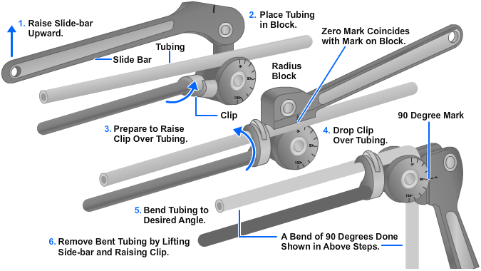
The hand tube bender shown in Figure 5-6 consists of a handle, a radius block, a clip, and a slide bar. The handle and slide bar are used as levers to provide the mechanical advantage necessary to bend the tubing. The radius block is marked in degrees of bend ranging from 0 to 180 degrees. The slide bar has a mark which is lined up with the zero mark on the radius block. The tube is inserted in the tube bender, and after the marks are lined up, the slide bar is moved around until the mark on the slide bar reaches the desired degree of bend on the radius block. The six procedural steps in tube bending with the hand-operated tube bender are shown in Figure 5-6.
Mechanical Tube Bender
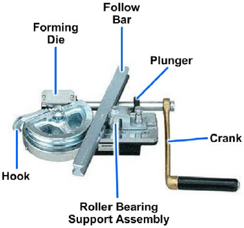
Mechanical tube benders (Figure 5-7) are considered the most practical and most accurate method of bending copper tubing. These benders are manufactured in many different sizes. When a tube is placed in the bender, the right handle of the bender should be raised as far as it will go so that it rests in a horizontal position. The clip should be raised and the tubing placed in the space between the handle and slide block and the bending form. The slip should now be placed over the tubing and the handle slide bar turned about its pin and to the right. The zero mark on the bending form will line up with the mark on the slide bar. Next, the handle should continue to be pulled to the right (clockwise), until the tubing is bent to the desired angle. When using the mechanical bending tool, bends may be made up to 180° without buckling or kinking the tubing.
Tube Flaring
Flaring is an easy and satisfactory method of joining copper tubing. The ends of the tubing should be flared and pressed against the tapered surface of the flared fitting. Next, the flare nut should be screwed over the end of the fitting.
An advantage of this type of connection is that it is easily disassembled when repairs are necessary. The only thing required to disassemble this connection is to select the correct size wrench, unscrew the flare nut that makes up the compression-type connection, and separate the fittings. When a flare is made on tubing, every precaution should be taken to produce an airtight and watertight joint. First, the tubing should be measured and cut to the proper length with a tubing cutter or hacksaw. Then, the burr within the tubing should be removed by reaming. Tubing can be flared with a flaring type tool (Figure 5-8).
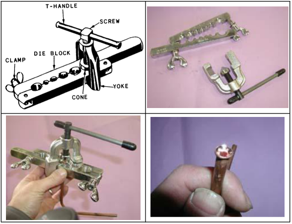
Before a flare is made, the flare nut should be slipped on the tubing and the end of the tubing inserted into the correct size hole in the flaring block. Then, the end of the tubing should be extended above the face of the block twice the wall thickness of the tubing.
Next, the flaring yoke should be attached to the flaring block and the flaring cone centered over the end of the tubing. The cone should be forced against the flaring block by rotating the handle on the flaring yoke clockwise. After the tubing has been flared properly, assembly of the joint is simple. After placing the flare against the fitting, the compression nut should be slipped against the flare and screwed on the fitting. This operation compresses the flare of the tubing between the fitting and nut.
Flexible Hose
Shock-resistant, flexible hose assemblies are required to absorb the movements of mounted equipment under both normal operating conditions and extreme conditions. They are also used for their noise-attenuating properties and to connect moving parts of certain equipment. There are two basic types of hoses used in military aircraft and related equipment. They are synthetic rubber and polytetrafluoroethylene (PTFE), commonly known as Teflon®.
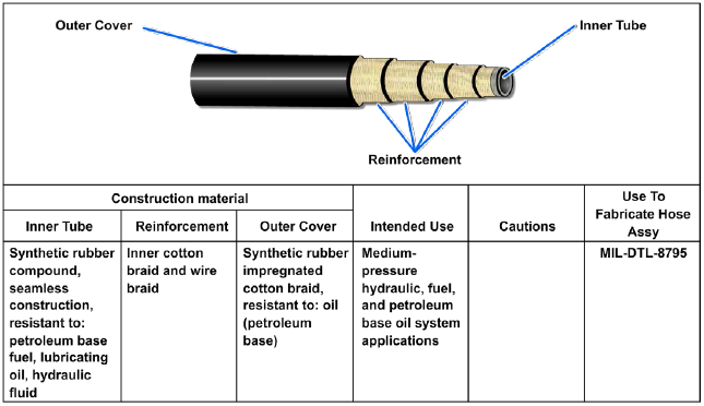
Rubber hoses are designed for specific fluid, temperature, and pressure ranges and are provided in various specifications. Rubber hoses (Figure 5-9) consist of a minimum of three layers; a seamless synthetic rubber tube reinforced with one or more layers of braided or spiraled cotton, wire, or synthetic fiber; and an outer cover. The inner tube is designed to withstand the attack of the fluid that passes through it. The braided or spiraled layers determine the strength of the hose; the greater the number of these layers, the greater the pressure rating. Hoses are provided in three pressure ranges: low, medium, and high. The outer cover is designed to withstand external abuse and contains identification markings.
Synthetic rubber hose (if rubber-covered) is identified by the indicator stripe and markings that are stenciled along the length of the hose. The indicator stripe (also called the lay line because of its use in determining the straightness or lie of a hose) is a series of dots or dashes. The markings (letters and numerals) contain the military specification, hose size, cure date, and manufacturer's Federal supply code number. This information is repeated at intervals of 9 inches (Figure 5-10).
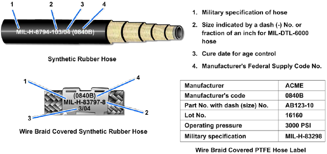
Size is indicated by a dash followed by a number (referred to as a dash number). The dash number does not denote the inside or outside diameter of the hose. It refers to the equivalent outside diameter of rigid tube size in sixteenths (1/16) of an inch. A dash 8 (-8) mates to a number 8 rigid tube, which has an outside diameter of one-half inch (8/16). The inside of the hose will not be one half inch, but slightly smaller to allow for tube thickness. The cure date is provided for age control. It is indicated by the quarter of the year and year. The year is divided into four quarters.
- 1st quarter — January, February, March
- 2rd quarter — April, May, June
- 3rd quarter — July, August, September
- 4th quarter — October, November, December
The cure date is also marked on bulk hose containers in accordance with Military Standard 129 (MIL-STD-129).
Synthetic rubber hose (if wire-braid covered) is identified by bands wrapped around the hose at the ends and at intervals along the length of the hose. Each band is marked with the same information (Figure 5-10).
Acceptance Life
The acceptance life for synthetic rubber hoses is the period of time from the cure date to the acceptance by the organizational-, Intermediate-, or Depot-level activity. Synthetic rubber hose and hose assemblies must have at least 8 1/2 years (34 quarters) of the shelf life remaining upon acceptance from the first Government activity receiving the material from the manufacturer.
Polytetrafluoroethylene (PTFE) (Teflon) Hose
The PTFE hose is a flexible hose designed to meet the requirements of higher operating pressures and temperatures in present fluid power systems. This type of hose is made from a chemical resin, which is processed and extruded into a tube shaped to a desired size. It is reinforced with one or more layers of braided stainless steel wire or with an even number of spiral wrap layers with an outer wire braid layer.
A PTFE hose is unaffected by all fluids presently used in fluid power systems. It is inert to acids, both concentrated and diluted. Certain PTFE hose may be used in systems where operating temperatures range from −100 to +500 degrees Fahrenheit (°F). PTFE is nonflammable; however, where the possibility of open flame exists, a special asbestos fire sleeve should be used.
A PTFE hose will not absorb moisture. This, together with its chemical inertness and antiadhesive characteristics, makes it ideal for missile fluid power systems where noncontamination and cleanliness are essential.
In lieu of layline marking, PTFE hoses are identified by metal or pliable plastic bands at their ends and at intervals along their length. Usually the only condition that will shorten the life of PTFE hose is excessive temperature. For this reason there is no manufacture date listed on the identification tag.
Application
As mentioned earlier, flexible hose is available in three pressure ranges: low, medium, and high. When replacing hoses, it is important to ensure that the replacement hose is a duplicate of the one removed in length, OD, material, type and contour, and associated markings. In selecting hose, several precautions must be observed. The selected hose must:
- Be compatible with the system fluid,
- Have a rated pressure greater than the design pressure of the system,
- Be designed to give adequate performance and service for infrequent transient pressure peaks up to 150 percent of the working pressure of the hose, and
- Have a safety factor with a burst pressure at a minimum of 4 times the rated working pressure.
There are temperature restrictions applied to the use of hoses. Rubber hose must not be used where the operating temperature exceeds 200 °F with the exception of MIL-H-24135/12 and MIL-H024135/13, which may be used up to 300 °F. PTFE hoses in high-pressure air systems must not be used where the temperature exceeds 350 °F. PTFE hoses in water and steam drain applications must not be used where the operating temperature exceeds 380 °F.
Fabrication and Testing
The fabrication of flexible hose assemblies is covered in applicable training manuals, technical publications, and the Aviation Hose and Tube Manual, NAVAIR 01-1A-20. After a hose assembly has been completely fabricated, it must be cleaned, visually inspected for foreign materials, and proof tested.
A hose assembly is proof tested by the application of a nondestructive pressure for a minimum of 1 minute but not longer than 5 minutes to ensure that it will withstand normal working pressures. The test pressure, known as normal proof pressure, is twice the rated working pressure. While the test pressure is being applied, the hose must not burst, leak, or show signs of fitting separation. NAVAIR 01-1A-20 and NAVSEA S6430-AE-TED-010, Volume 1, provide detailed instructions on cleaning of hoses, cleaning and test media, proof pressure, and proof testing.
After proof testing is completed, the hose must be flushed and dried and the ends capped or plugged to keep dirt and other contaminants out of the hose.
Identification
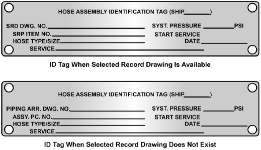
The final step after fabrication and satisfactory testing of a hose assembly is the attachment of identification tags as shown in Figure 5-11 (for ships). Hose assemblies to be installed in aircraft fuel and oil tanks are marked with an approved electric engraver on the socket-wrench flats with the required information.
Installation
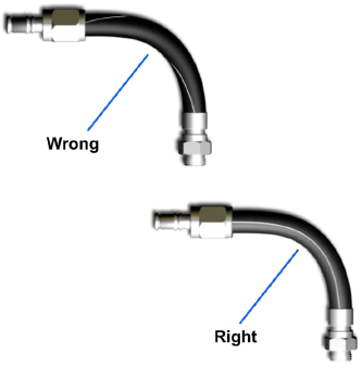
Flexible hose must not be twisted during installation, since this reduces the life of the hose considerably and may cause the fittings to loosen as well. To determine whether a hose is twisted or not, the layline that runs along the length of the hose should be straight. If the layline does not spiral around the hose, the hose is not twisted. If the layline does spiral around the hose, the hose is twisted (Figure 5-12) and must be untwisted.
Flexible hose should be protected from chafing by using a chafe-resistant covering wherever necessary.
The minimum bend radius for flexible hose varies according to the size and construction of the hose and the pressure under which the system operates. Current applicable technical publications contain tables and graphs showing minimum bend radii for the different types of installations. Bends that are too sharp will reduce the bursting pressure of flexible hose considerably below its rated value.
Flexible hose should be installed so that it will be subjected to a minimum of flexing during operation. Support clamps are not necessary with short installations; but for hose of considerable length (48 inches, for example), clamps should be placed not more than 24 inches apart. Closer supports are desirable and in some cases may be required.
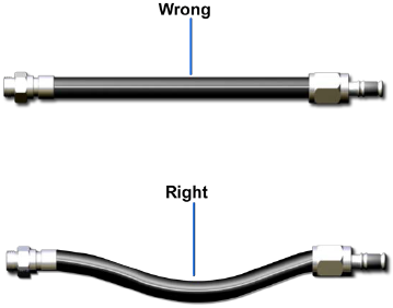
A flexible hose must never be stretched tightly between two fittings. About 5 to 8 percent of the total length must be allowed as slack to provide freedom of movement under pressure. When under pressure, flexible hose contracts in length and expands in diameter. Examples of correct and incorrect installations of flexible hose are illustrated in Figure 5-13.
PTFE hose should be handled carefully during removal and installation. Some PTFE hose is preformed during fabrication. This type of hose tends to form itself to the installed position in the system. To ensure its satisfactory function and reduce the likelihood of failure, anyone who works with PTFE hose should observe the following rules:
- Do not exceed recommended bend limits.
- Do not exceed twisting limits.
- Do not straighten a bent hose that has taken a permanent set.
- Do not hang, lift, or support objects from PTFE hose.
Once flexible hose assemblies are installed, there are no servicing or maintenance requirements other than periodic inspections. These inspections are conducted according to maintenance instruction manuals (MIMs), maintenance requirement cards (MRCs), and depot-level specifications.
Types of Fittings and Connectors
Some type of connector or fitting must be provided to attach the lines to the components of the system and to connect sections of line to each other. There are many different types of connectors and fittings provided for this purpose. The type of connector or fitting required for a specific system depends on several factors. One determining factor, of course, is the type of fluid line (pipe, tubing, or flexible hose) used in the system. Other determining factors are the type of fluid medium and the maximum operating pressure of the system. Some of the most common types of fittings and connectors are described in the following paragraphs.
Threaded Connectors
There are several different types of threaded connectors. In the type discussed in this section, both the connector and the end of the fluid line (pipe) are threaded. These connectors are used in some low-pressure fluid power systems and are usually made of steel, copper, or brass, and are available in a variety of designs.
Threaded connectors are made with standard pipe threads cut on the inside surface. The end of the pipe is threaded with outside threads. Standard pipe threads are tapered slightly to ensure tight connections. The amount of taper is approximately 3/4-inch in diameter per foot of thread.
Metal is removed when a pipe is threaded, thinning the pipe and exposing new and rough surfaces. Corrosion agents work more quickly at such points than elsewhere. If pipes are assembled with no protective compound on the threads, corrosion sets in at once and the two sections stick together so that the threads seize when disassembly is attempted. The result is damaged threads and pipes.
To prevent seizing, a suitable pipe thread compound is sometimes applied to the threads. The two end threads must be kept free of compound so that it will not contaminate the fluid. Pipe compound, when improperly applied, may get inside the lines and components and damage pumps and control equipment.
Another material used on pipe threads is sealant tape. This tape, which is made of PTFE, provides an effective means of sealing pipe connections and eliminates the necessity of torqueing connections to excessively high values in order to prevent pressure leaks. It also provides for ease of maintenance whenever it is necessary to disconnect pipe joints. The tape is applied over the male threads, leaving the first thread exposed. After the tape is pressed firmly against the threads, the joint is connected.
Flange Connectors
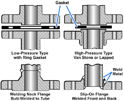
Bolted flange connectors (Figure 5-14) are suitable for most pressures now in use. The flanges are attached to the piping by welding, brazing, tapered threads (for some low-pressure systems), or rolling and bending into recesses. Those illustrated are the most common types of flange joints used. The same types of standard fitting shapes (tee, cross, elbow, and so forth) are manufactured for flange joints. Suitable gasket material must be used between the flanges.
Welded Connectors
The subassemblies of some fluid power systems are connected by welded joints, especially in high-pressure systems which use pipe for fluid lines. The welding is done according to standard specifications which define the materials and techniques.
Brazed Connectors
Silver-brazed connectors are commonly used for joining nonferrous (copper, brass, and soon) piping in the pressure and temperature range where their use is practical. Use of this type of connector is limited to installations in which the piping temperature will not exceed 425 °F and the pressure in cold lines will not exceed 3,000 pounds per square inch (psi). The alloy is melted by heating the joint with an oxyacetylene torch. This causes the alloy insert to melt and fill the few thousandths of an inch annular space between the pipe and the fitting.
A fitting of this type, which has been removed from a piping system, can be rebrazed into a system, as in most cases sufficient alloy remains in the insert groove for a second joint. New alloy inserts may be obtained for fittings which do not have sufficient alloy remaining in the insert for making a new joint.
Flared Connectors
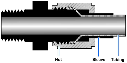
Flared connectors are commonly used in fluid power systems containing lines made of tubing. These connectors provide safe, strong, dependable connections without the need for threading, welding, or soldering the tubing. The connector consists of a fitting, a sleeve, and a nut (Figure 5-15).
The fittings are made of steel, aluminum alloy, or bronze. The fitting used in a connection should be made of the same material as that of the sleeve, the nut, and the tubing. For example, steel connectors should be used with steel tubing and aluminum alloy connectors with aluminum alloy tubing. Fittings are made in union; 45-degree and 90-degree elbow, tee, and various other shapes (Figure 5-16).
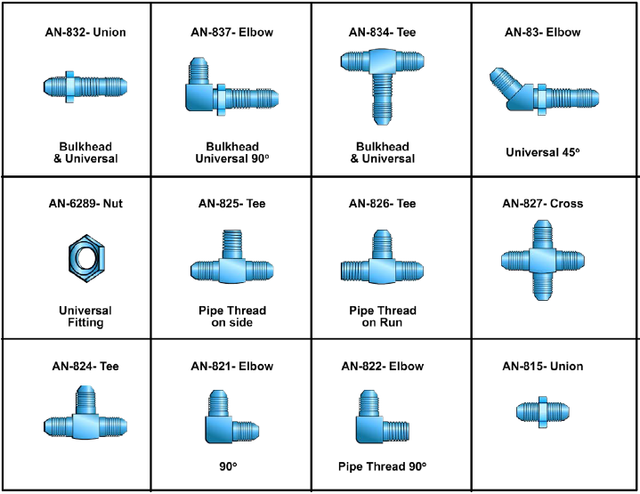
Tees, crosses, and elbows are self-explanatory. Universal and bulkhead fittings can be mounted solidly with one outlet of the fitting extending through a bulkhead and the other outlet(s) positioned at any angle. Universal means the fitting can assume the angle required for the specific installation. Bulkhead means the fitting is long enough to pass through a bulkhead and is designed so it can be secured solidly to the bulkhead.
For connecting to tubing, the ends of the fittings are threaded with straight machine threads to correspond with the female threads of the nut. In some cases, however, one end of the fitting may be threaded with tapered pipe threads to fit threaded ports in pumps, valves, and other components.
Tubing used with flare connectors must be flared prior to assembly. The nut fits over the sleeve and when tightened, it draws the sleeve and tubing flare tightly against the male fitting to form a seal.
The male fitting has a cone-shaped surface with the same angle as the inside of the flare. The sleeve supports the tube so vibration does not concentrate at the edge of the flare, and distributes the shearing action over a wider area for added strength.
Correct and incorrect methods of installing flared-tube connectors are illustrated in Figure 5-17. Tubing nuts should be tightened with a torque wrench to the value specified in applicable technical publications.
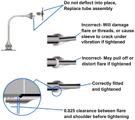
If an aluminum alloy flared connector leaks after being tightened to the required torque, it must not be tightened further. Overtightening may severely damage or completely cut off the tubing flare or may result in damage to the sleeve or nut. The leaking connection must be disassembled and the fault corrected.
If a steel tube connection leaks, it may be tightened 1/6 turn beyond the specified torque in an attempt to stop the leakage; then if it still leaks, it must be disassembled and repaired.
Undertightening of connections may be serious, as this can allow the tubing to leak at the connector because of insufficient grip on the flare by the sleeve. The use of a torque wrench will prevent undertightening.
Never tighten a nut when there is pressure in the line; damage to the connection may occur without adding any appreciable torque to the connection.
Flareless-Tube Connectors
This type of connector eliminates all tube flaring, yet provides a safe, strong, and dependable tube connection. This connector consists of a fitting, a sleeve or ferrule, and a nut. (Figure 5-18).
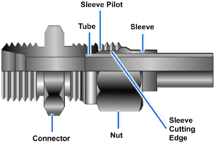
Although the use of flareless tube connectors is widespread, NAVSEA policy is to reduce or eliminate use of flareless fittings in newly designed ships; the extent to which flareless fittings are approved for use in a particular ship is reflected in applicable ship drawings.
Flareless-tube fittings are available in many of the same shapes and thread combinations as flared-tube fittings. The fitting has a counterbore shoulder for the end of the tubing to rest against. The angle of the counterbore causes the cutting edge of the sleeve or ferrule to cut into the outside surface of the tube when the two are assembled.
The nut presses on the bevel of the sleeve and causes it to clamp tightly to the tube. Resistance to vibration is concentrated at this point rather than at the sleeve cut. When fully tightened, the sleeve or ferrule is bowed slightly at the midsection and acts as a spring. This spring action of the sleeve or ferrule maintains a constant tension between the body and the nut and thus prevents the nut from loosening.
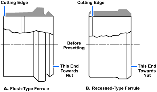
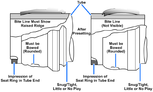
Prior to the installation of a new flareless-tube connector, the end of the tubing must be square, concentric, and free of burrs. For the connection to be effective, the cutting edge of the sleeve or ferrule must bite into the periphery of the tube (Figure 5-19). This is ensured by presetting the sleeve or ferrule on the tube.
Presetting
Presetting consists of deforming the ferrule to bite into the tube OD and deforming the end of the tube to form a shallow conical ring seating surface. The tube and ferrule assembly should be preset in a presetting tool that has an end section identical to a fitting body but which is made of specially hardened steel. This tool hardness is needed to ensure that all deformation at the tube end seat goes into the tube.
Presetting is done with a hydraulic presetting tool or a manual presetting tool, either in the shop or aboard ship. The tool vendor's instructions must be followed for the hydraulic presetting tool. If a presetting tool is not available, the fitting body intended for installation is used in the same manner as the manual presetting tool. (If an aluminum fitting is used, it should not be reused in the system.) The manual tool is used as follows:
Failure to follow these instructions may result in improperly preset ferrules with insufficient bite into the tube. Improperly preset ferrules have resulted in joints that passed hydrostatic testing and operated for weeks or years, then failed catastrophically under shock, vibration, or normal operating loads. Flareless fitting failures have caused personnel injury, damage to equipment, and unnecessary interruption of propulsion power.
- Cut the tubing square and lightly deburr the inside and outside corners. For corrosion resisting steel (CRES) tubing, use a hacksaw rather than a tubing cutter to avoid work hardening the tube end. For CRES, and if necessary for other materials, dress the tube end smooth and square with a file. Tube ends with irregular cutting marks will not produce satisfactory seating surface impressions.
- Test the hardness of the ferrule by making a light scratch on the tubing at least 1/2 inch back from the tube end, using a sharp corner on the ferrule. If the ferrule will not scratch the tube, no bite will be obtained. This test may be omitted for flush-type ferrules where the bite will be visible. Moderate hand pressure is sufficient for producing the scratch.
- Lubricate the nut threads, the ferrule leading and trailing edges, and the preset tool threads with a thread lubricant compatible with the system. Slide the nut onto the tubing so the threads face the tube end. Note whether the ferrule is a flush-type or recessed-type (Figure 5-19), and slide the ferrule onto the tube so the cutting edge is toward the tube end (large end toward the nut).
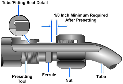
- Bottom the end of the tubing in the presetting tool. Slide the ferrule up into the presetting tool, and confirm that the nut can be moved down the tube sufficiently to expose at least 1/8 of an inch of tubing past the ferrule after the presetting operation (Figure 5-20) to allow for inspection of the ferrule.
- While keeping the tube bottomed in the presetting tool, tighten the nut onto the fitting body until the ferrule just grips the tube by friction. This ring grip point may be identified by lightly turning the tube or the presetting tool and slowly tightening the nut until the tube cannot be turned in the presetting tool by hand. Mark the nut and the presetting tool at this position.
- Tighten the nut according to the number of turns given in Table 5-3, depending on tube size.
| Tube OD Inches | Number of Turns |
|---|---|
| 1/8 to 1/2 | 1-1/6 (seven flats of the nut) |
| 5/8 to 7/8 | 1 (six flats) |
| 1 | 5/6 (five flats) |
| 1-1/4 to 2 | 1 (six flats) |
Inspection
Disassemble and inspect the fitting as follows (mandatory):
- Ensure that the end of the tubing has an impression of the presetting tool seat surface (circular appearing ring) for 360 degrees. A partial circle, a visibly off-center circle, or a circle broken by the roughness of the tube end is unsatisfactory.
-
Check for proper bite:
- For flush-type ferrules, a raised ridge (Figure 5-21) of tube metal must be visible completely around the tube at the leading edge of the ferrule. The best practice is to obtain a ridge about 50 percent of the ferrule edge thickness.
- For recessed-type ferrules, the leading edge must be snug against the tube OD. Determine this visually and by attempting to rock the ferrule on the tube.
- Ensure that the nut end of the ferrule (both types) is collapsed around the tube to provide support against bending loads and vibration.
- The ferrule (both types) must have little or no play along the direction of the tube run. Check this by trying to move the ferrule back and forth by hand. The ferrule will often be free to rotate on the tubing; this does not affect its function.
- For flush-type ferrules, check that the gap between the raised metal ridge and the cutting end of the ferrule stays the same while the ferrule is rotated. (Omit this check for recessed-type ferrules or if the flush-type ferrule will not rotate on the tube).
- Check that the middle portion of the ferrule (both types) is bowed or sprung into an arc. The leading edge of the ferrule may appear flattened into a cone shape; this is acceptable as long as there is a bowed section near the middle of the ferrule. If the whole leading section of the ferrule is flattened into a cone with no bowed section, the ferrule (and possibly the fitting body, if used) has been damaged by overtightening and will not seal reliably.
Final Assembly
The following installation procedure should be used to make a final assembly in the system:
- Lubricate all threads with a liquid that is compatible with the fluid to be used in the system.
- Place the tube assembly in position and check for alignment.
- Tighten the nut by hand until you feel an increase in resistance to turning. This indicates that the sleeve or ferrule pilot has contacted the fitting.
-
If possible, use a torque wrench to tighten flareless tubing nuts. Torque values for specific installations are usually listed in the applicable technical publications. If it is not possible to use a torque wrench, the following discussion describes a process for tightening the nuts:
After the nut is handtight, turn the nut 1/6 turn (one flat on a hex nut) with a wrench. Use a wrench on the connector to prevent it from turning while tightening the nut. After you install the tube assembly, have the system pressure tested. Should a connection leak, you may tighten the nut an additional 1/6 turn (making a total of 1/3 turn). If, after tightening the nut a total of 1/3 turn, leakage still exists, remove the assembly and inspect the components of the assembly for scores, cracks, presence of foreign material, or damage from overtightening.
Overtightening a flareless-tube nut drives the cutting edge of the sleeve or ferrule deeply into the tube, causing the tube to be weakened to the point where normal vibration could cause the tube to shear.
Do not (in any case) tighten the nut beyond 1/3 turn (two flats on the hex nut); this is the maximum the fitting may be tightened without the possibility of permanently damaging the sleeve or the tube.
Connectors for Flexible Hose
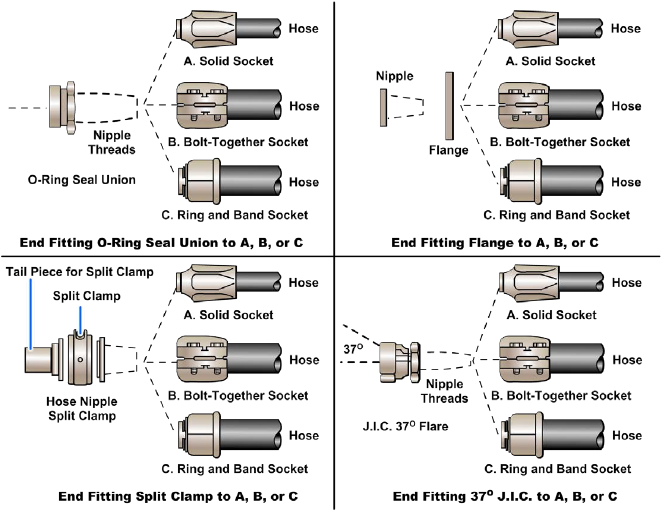
As stated previously, the fabrication of flexible hose assemblies is covered in applicable training manuals, technical publications, and NAVAIR 01-1A-20. There are various types of end fittings for both the piping connection side and the hose connection side of hose fittings (Figure 5-22).
Piping Connection Side of Hose Fitting
The piping side of an end fitting comes with several connecting variations: flange, Joint Industry Council (JIC) 37-degree flare, O-ring union, and split clamp, to name a few. Not all varieties are available for each hose. Therefore, installers must consult the military specification and manufacturer's data to determine the specific end fittings available.
Hose Connection Side of Hose Fitting
Hose fittings are attached to the hose by several methods. Each method is determined by the fitting manufacturer and takes into consideration such things as size, construction, wall thickness, and pressure rating. Hoses used for flexible connections use one of the following methods for attachment of the fitting to the hose.
One-Piece Reusable Socket
The socket component of the fitting is fabricated as a single piece. One-piece reusable sockets are screwed or rocked onto the hose OD, followed by insertion of the nipple component.
Segmented, Bolted Socket
The segmented, bolted socket consists of two or more segments which are bolted together on the hose after insertion of the nipple component.
Segmented Socket, Ring and Band Attached
The segmented, ring and band attached socket consists of three or more segments. As with the bolt-together segments, the segments, ring and band are put on the hose after insertion of the nipple. A special tool is required to compress the segments.
Segmented Socket, Ring and Bolt Attached
The segmented, ring and bolt attached socket consists of three or more segments. As with other segmented socket-type fittings, the segments, ring, and nuts and bolts are put on the hose after insertion of the nipple.
Solid Socket, Permanently Attached
This type of socket is permanently attached to the hose by crimping or swaging. It is not reusable and is only found on hose assemblies where operating conditions preclude the use of other fitting types. Hose assemblies with this type of fitting attachment are purchased as complete hose assemblies from the manufacturer.
Quick-Disconnect Couplings
Self-sealing, quick-disconnect couplings are used at various points in many fluid power systems. These couplings are installed at locations where frequent uncoupling of the lines is required for inspection, test, and maintenance. Quick-disconnect couplings are also commonly used in pneumatic systems to connect sections of air hose and to connect tools to the air pressure lines. This provides a convenient method of attaching and detaching tools and sections of lines without losing pressure.
Quick-disconnect couplings provide a means for quickly disconnecting a line without the loss of fluid from the system or the entrance of foreign matter into the system. Several types of quick-disconnect couplings have been designed for use in fluid power systems. A coupling that is used with portable pneumatic tools is illustrated in Figure 5-23. The male section is connected to the tool or to the line leading from the tool. The female section, which contains the shutoff valve, is installed in the pneumatic line leading from the pressure source. These connectors can be separated or connected by very little effort on the part of the operator.
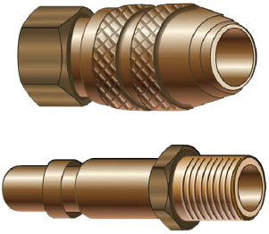
The most common quick-disconnect coupling for hydraulic systems consists of two parts, held together by a union nut. Each part contains a valve which is held open when the coupling is connected, allowing fluid to flow in either direction through the coupling. When the coupling is disconnected, a spring in each part closes the valve, preventing the loss of fluid and entrance of foreign matter.
Manifolds
Some fluid power systems are equipped with manifolds in the pressure supply and/or return lines. A manifold is a fluid conductor that provides multiple connection ports. Manifolds eliminate piping, reduce joints (which are often a source of leakage), and conserve space. For example, manifolds may be used in systems that contain several subsystems. One common line connects the pump to the manifold. There are outlet ports in the manifold to provide connections to each subsystem. A similar manifold may be used in the return system. Lines from the control valves of the subsystem connect to the inlet ports of the manifold, where the fluid combines into one outlet line to the reservoir. Some manifolds are equipped with the check valves, relief valves, filters, and so on, required for the system. In some cases, the control valves are mounted on the manifold in such a manner that the ports of the valves are connected directly to the manifold.
Manifolds are usually one of three types — sandwich, cast, or drilled. The sandwich-type is constructed of three or more flat plates. The center plate (or plates) is machined for passages, and the required inlet and outlet ports are drilled into the outer plates. The plates are then bonded together to provide a leakproof assembly. The cast-type of manifold is designed with cast passages and drilled ports. The casting may be iron, steel, bronze, or aluminum, depending upon the type of system and fluid medium. In the drilled-type of manifold, all ports and passages are drilled in a block of metal.
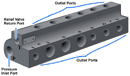
A simple manifold is illustrated in Figure 5-24. This manifold contains one pressure inlet port and several pressure outlet ports that can be blocked off with threaded plugs. This type of manifold can be adapted to systems containing various numbers of subsystems. A thermal relief valve may be incorporated in this manifold. In this case, the port labeled T is connected to the return line to provide a passage for the relieved fluid to flow to the reservoir.
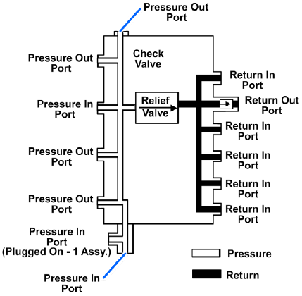
A flow diagram in a manifold (Figure 5-25) shows both pressure and return passages. One common line provides pressurized fluid to the manifold, which distributes the fluid to any one of five outlet ports. The return side of the manifold is similar in design. This manifold is provided with a relief valve, which is connected to the pressure and return passages. In the event of excessive pressure, the relief valve opens and allows the fluid to flow from the pressure side of the manifold to the return side.
Precautionary Measures
The fabrication, installation, and maintenance of all fluid lines and connectors are beyond the scope of this training manual. However, there are some general precautionary measures that apply to the maintenance of all fluid lines.
Regardless of the type of lines or connectors used to make up a fluid power system, they must be the correct size and strength and perfectly clean on the inside. All lines must be absolutely clean and free from scale and other foreign matter. Iron or steel pipes, tubing, and fittings can be cleaned with a boiler tube wire brush or with commercial pipe cleaning apparatus. Rust and scale can be removed from short, straight pieces by sandblasting, provided there is no danger that sand particles will remain lodged in blind holes or pockets after the piece is flushed. In the case of long pieces or pieces bent to complex shapes, rust and scale can be removed by pickling (cleaning metal in a chemical bath). Parts must be degreased prior to pickling. The manufacturer of the parts should provide complete pickling instructions.
Open ends of pipes, tubing, hose, and fittings should be capped or plugged when they are to be stored for any considerable period. Rags or waste must not be used for this purpose, because they deposit harmful lint which can cause severe damage to the fluid power system.
PDH Classroom offers a continuing education course based on this fluid lines and fittings reference page. This course can be used to fulfill PDH credit requirements for maintaining your PE license.
Now that you've read this reference page, earn credit for it!
