Chapter 10: Actuators
This page provides the chapter on hydraulic actuators from the U.S. Navy's fluid power training course, NAVEDTRA 14105A, "Fluid Power," Naval Education and Training Professional Development and Technology Center, July 2015.
Other related chapters from the Navy's fluid power training course can be seen to the right.
Actuators
One of the outstanding features of fluid power systems is that force, generated by the power supply, controlled and directed by suitable valving, and transported by lines, can be converted with ease to almost any kind of mechanical motion desired at the very place it is needed. Either linear (straight line) or rotary motion can be obtained by using a suitable actuating device.
An actuator is a device that converts fluid power into mechanical force and motion. Cylinders, motors, and turbines are the most common types of actuating devices used in fluid power systems.
This chapter describes various types of actuating cylinders and their applications, different types of fluid motors, and turbines used in fluid power systems.
Learning Objectives
When you have completed this chapter, you will be able to do the following:
- Recognize the types of fluid power actuating devices.
- Identify the construction features and uses of the various types of actuating cylinders.
- Identify the operating characteristics of various types of actuating cylinders.
- Recognize the different types of fluid power motors.
- Identify functions and operating characteristics of various types of turbines.
- Identify the construction features of various types of turbines.
Cylinders
An actuating cylinder is a device that converts fluid power to linear, force, and motion. Since linear motion is a back-and-forth motion along a straight line, this type of actuator is sometimes referred to as a reciprocating, or linear, motor. The cylinder consists of a ram or piston operating within a cylindrical bore. Actuating cylinders may be installed so that the cylinder is anchored to a stationary structure and the ram or piston is attached to the mechanism to be operated. The piston or ram could also be anchored to the stationary structure and the cylinder attached to the mechanism to be operated.
Actuating cylinders for pneumatic and hydraulic systems are similar in design and operation. Some of the variations of ram- and piston-type actuating cylinders are described in the following paragraphs.
Ram-Type Cylinders
The terms ram and piston are often used interchangeably. However, a ram-type cylinder is usually considered one in which the cross-sectional area of the piston rod is more than one-half the cross-sectional area of the movable element. In most actuating cylinders of this type, the rod and the movable element have equal areas. This type of movable element is frequently referred to as a plunger.
The ram-type actuator is used primarily to push rather than to pull. Some applications require simply a flat surface on the external part of the ram for pushing or lifting the unit to be operated. Other applications require some mechanical means of attachment, such as a clevis or eyebolt. The design of ram-type cylinders varies in many other respects to satisfy the requirements of different applications.
Single-Acting Ram
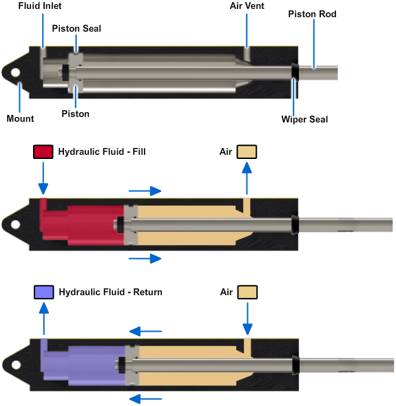
The single-acting ram (Figure 10-1) applies force in only one direction. Fluid directed into the cylinder displaces the ram and forces it outward. Since there is no provision for retracting the ram by the use of fluid power, the retracting force can be gravity or some mechanical means, such as a spring. This type of actuating cylinder is often used in the hydraulic jack.
Double-Acting Ram
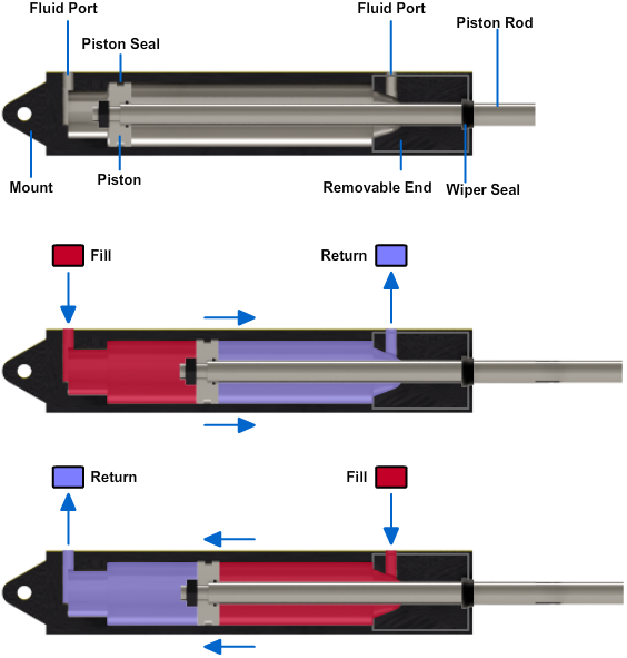
A double-acting ram type of cylinder is illustrated in Figure 10-2. In this cylinder, both strokes of the ram are produced by pressurized fluid. There are two fluid ports — one at or near each end of the cylinder. To extend the ram and apply force, fluid under pressure is directed to the closed end of the cylinder through one port.
Telescoping Rams
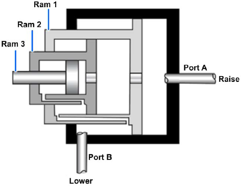
Figure 10-3 shows a telescoping ram-type actuating cylinder. A series of rams are nested in the telescoping assembly. With the exception of the smallest ram, each ram is hollow and serves as the cylinder housing for the next smaller ram. The ram assembly is contained in the main cylinder assembly, which also provides the fluid ports. Although the assembly requires a small space with all the rams retracted, the telescoping action of the assembly provides a relatively long stroke when the rams are extended.
An excellent example of the application of this type of cylinder is in the dump truck. It is used to lift the forward end of the truck bed and dump the load. During the lifting operation, the greatest force is required for the initial lifting of the load.
As the load is lifted and begins to dump, the required force becomes less and less until the load is completely dumped. During the raise cycle, pressurized fluid enters the cylinder through port A (Figure 10-3) and acts on the bottom surface of all three rams. Ram 1 has a larger surface area and, therefore, provides the greater force for the initial load. As ram 1 reaches the end of its stroke and the required force is decreased, ram 2 moves, providing the smaller force needed to continue raising the load. When ram 2 completes its stroke, a still smaller force is required. Ram 3 then moves outward to finish raising and dumping the load.
Some telescoping ram-type cylinders are of the single-acting type. Like the single-acting ram discussed previously, these telescoping ram-type cylinders are retracted by gravity or mechanical force. Some hydraulic jacks are equipped with telescoping rams. Such jacks are used to lift vehicles with low clearances to the required height.
Other types of telescoping cylinders, like the one illustrated in Figure 10-3, are of the double-acting type. In this type, fluid pressure is used for both the extension and retraction strokes. A four-way directional control valve is commonly used to control the operation of the double-acting type. Note the small passages in the walls of rams 1 and 2. They provide a path for fluid to flow to and from the chambers above the lips of rams 2 and 3. During the extension stroke, return fluid flows through these passages and out of the cylinder through port B. It then flows through the directional control valve to the return line or reservoir.
To retract the rams, fluid under pressure is directed into the cylinder through port B and acts against the top surface areas of all three ram lips. This pressure forces the rams to the retracted position. The displaced fluid from the opposite side of the rams flows out of the cylinder through port A, through the directional control valve to the return line or reservoir.
Dual Rams
A dual ram assembly consists of a single ram with a cylinder at either end (Figure 10-4). Fluid can be directed to either cylinder, forcing the ram to move in the opposite direction. The ram is connected through mechanical linkage to the unit to be operated. A four-way directional control valve is commonly used to operate the dual ram. When the control valve is positioned to direct fluid under pressure to one of the cylinders (let's say the left one), the ram is forced to the right. This action displaces the fluid in the opposite cylinder. The displaced fluid flows back through the directional control valve to the return line or reservoir in hydraulic systems or to the atmosphere in pneumatic systems.
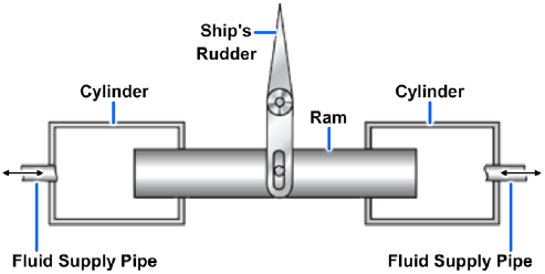
Dual ram actuating assemblies are used in steering systems of most ships. In some systems, one assembly is used to actuate the rudder in either direction; while in other systems, two assemblies are used for the same purpose.
Piston-Type Cylinders
The piston type of cylinder is normally used for applications that require both push and pull functions. Thus, the piston type serves many more requirements than the ram type, and therefore is the most common type used in fluid power systems.
The essential parts of a piston-type cylinder are a cylindrical barrel, a piston and rod, end caps, and suitable seals. The end caps are attached to the ends of the barrel. These end caps usually contain the fluid ports. The end cap on the rod end contains a hole for the piston rod to pass through. Suitable seals are used between the hole and the piston rod to keep fluid from leaking out and to keep dirt and other contaminants from entering the barrel. The opposite end cap of most cylinders is provided with a fitting for securing the actuating cylinder to some structure. This end cap is referred to as the anchor end cap.
The piston rod may extend through either or both ends of the cylinder. The extended end of the rod is normally threaded so that some type of mechanical connector, such as an eyebolt or a clevis, and a locknut can be attached. This threaded connection of the rod and mechanical connector provides for adjustment between the rod and the unit to be actuated. After the correct adjustment is made, the locknut is tightened against the connector to prevent the connector from turning. The other end of the eyebolt or clevis is connected to the unit to be actuated, either directly or through additional mechanical linkage.
In order to satisfy the many requirements of fluid power systems, piston-type cylinders are available in various designs.
Single-Acting Actuating Cylinder
The single-acting, piston-type cylinder uses fluid pressure to apply force in only one direction. In some designs of this type, the force of gravity moves the piston in the opposite direction. However, most cylinders of this type apply force in both directions. Fluid pressure provides the force in one direction, and spring tension provides the force in the opposite direction. In some single-acting cylinders, compressed air or nitrogen is used instead of a spring for movement in the direction opposite that which is achieved with fluid pressure.
Figure 10-5 shows a single-acting, spring-loaded, piston-type actuating cylinder. In this cylinder the spring is located on the rod side of the piston. In some spring-loaded cylinders, the spring is located on the blank side, and the fluid port is located on the rod side of the cylinder.
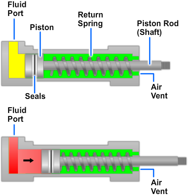
A three-way directional control valve is normally used to control the operation of the single-acting piston-type cylinder. To extend the piston rod, fluid under pressure is directed through the port into the cylinder (Figure 10-5). This pressure acts on the surface area of the blank side of the piston and forces the piston to the right. This action moves the rod to the right, through the end of the cylinder, thus moving the actuated unit in one direction. During this action, the spring is compressed between the rod side of the piston and the end of the cylinder. The length of the stroke depends upon the physical limits within the cylinder and the required movement of the actuated unit.
To retract the piston rod, the directional control valve is moved to the opposite working position, which releases the pressure in the cylinder. The spring tension forces the piston to the left, retracting the piston rod and moving the actuated unit in the opposite direction. The fluid is free to flow from the cylinder through the port, back through the control valve to the return line in hydraulic systems or to the atmosphere in pneumatic systems.
The end of the cylinder opposite the fluid port is vented to the atmosphere. This vent prevents air from being trapped in this area. Any trapped air would compress during the extension stroke, creating excess pressure on the rod side of the piston. The trapped air can cause sluggish movement of the piston and could eventually cause a complete lock, preventing the fluid pressure from moving the piston.
Seals prevent leakage between the cylinder wall and the piston. Hydraulic components use seals or gaskets to prevent leakage between static parts (nonmoving), such as a valve body and a hydraulic line fitting. Seals also prevent leakage between dynamic (moving) parts, such as the piston and cylinder wall. The most common seal is an O-ring. Some static seals and all dynamic seals require a backup ring or rings.
Double-Acting Cylinder
Most piston-type actuating cylinders are double-acting, which means that fluid under pressure can be applied to either side of the piston to apply force and provide movement.
One design of the double-acting piston-type actuating cylinder is shown in view A of Figure 10-6. This cylinder contains one piston and piston rod assembly. The stroke of the piston and piston rod assembly in either direction is produced by fluid pressure. The two fluid ports−one near each end of the cylinder−alternate as inlet and outlet ports, depending on the direction of flow from the directional control valve.
This actuator (Figure 10-6, view A) is referred to as an unbalanced actuating cylinder because of the difference in the effective working areas on the two sides of the piston. Therefore, this type of cylinder is normally installed so the blank side of the piston carries the greater load; that is, the cylinder carries the greater load during the piston rod extension stroke.
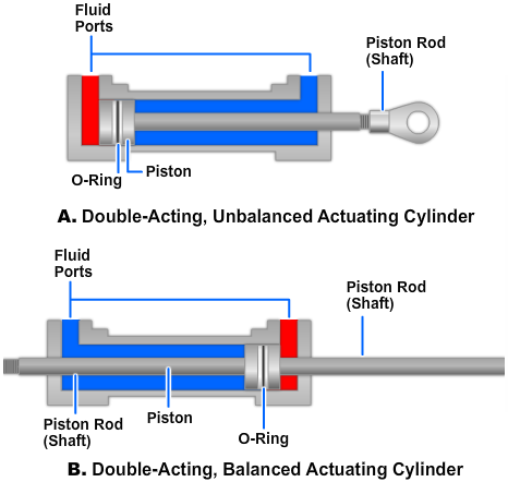
A four-way directional control valve is normally used to control the operation of this type of cylinder. The valve can be positioned to direct fluid under pressure to either end of the cylinder and allow the displaced fluid to flow from the opposite end of the cylinder through the control valve to the return line in hydraulic systems or to the atmosphere in pneumatic systems.
The piston of the cylinder shown in view A of Figure 10-6 is equipped with an O-ring seal and backup rings to prevent internal leakage of fluid from one side of the piston to the other. Suitable seals and backup rings are also used between the hole in the end cap and the piston rod to prevent external leakage. In addition, some cylinders of this type have a felt wiper ring attached to the inside of the end cap and fitted around the piston rod to guard against the entrance of dirt and other foreign matter into the cylinder. The actuating cylinder shown in view B of Figure 10-6 is a double-acting-balanced type. The piston rod extends through the piston and out through both ends of the cylinder. One or both ends of the piston rod may be attached to a mechanism to be actuated. In either case, the cylinder provides equal areas on each side of the piston so that the amount of fluid and force required to move the piston a certain distance in one direction is exactly the same as the amount required to move it an equal distance in the opposite direction.
Actuators are designed for a particular type of installation. For example, internal locking cylinders are used on some bomb bay door installations, while cushioned types are used where it is necessary to slow the extension or retraction of landing gears.
Tandem Cylinders
A tandem actuating cylinder consists of two or more cylinders arranged one behind the other but designed as a single unit (Figure 10-7). This type of actuating cylinder is used in applications that require two or more independent systems; for example, power-operated flight control systems in naval aircraft.

The flow of fluid to and from the two chambers of the tandem actuating cylinder is provided from two independent hydraulic systems and is controlled by two sliding spool directional control valves. In some applications, the control valves and the actuating cylinder are two separate units. In some units, the pistons (lands) of the two sliding spools are machined on one common shaft. In other applications, the valves and the actuator are directly connected in one compact unit. Although the two control valves are hydraulically independent, they are interconnected mechanically. In other units, the two sliding spools are connected through mechanical linkages with a synchronizing rod. In either case, the movement of the two sliding spools is synchronized, thus equalizing the flow of fluid to and from the two chambers of the actuating cylinder.
Since the two control valves operate independently of each other as far as hydraulic pressure is concerned, failure of either hydraulic system does not render the actuator inoperative. Failure of one system does reduce the output force by one-half; however, this force is sufficient to permit operation of the actuator.
Rack-and-Pinion Piston-Type Rotary Actuators
The rack-and-pinion-type actuators, also referred to as limited rotation cylinders, of the single or multiple, bidirectional piston are used for turning, positioning, steering, opening and closing, swinging, or any other mechanical function involving restricted rotation. Figure 10-8 shows a rack-and-pinion double-piston rotary actuator.
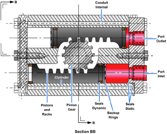
The actuator consists of a body and two reciprocating pistons with an integral rack for rotating the shaft mounted in roller or journal bearings. The shaft and bearings are located in a central position and are enclosed with a bearing cap. The pistons−one on each side of the rack−are enclosed in cylinders machined or sleeved into the body. The body is enclosed with end caps and static seals to prevent external leakage of pressurized fluid.
Only a few of the many applications of actuating cylinders were discussed in the preceding paragraphs. Figure 10-9 shows additional types of force and motion applications.
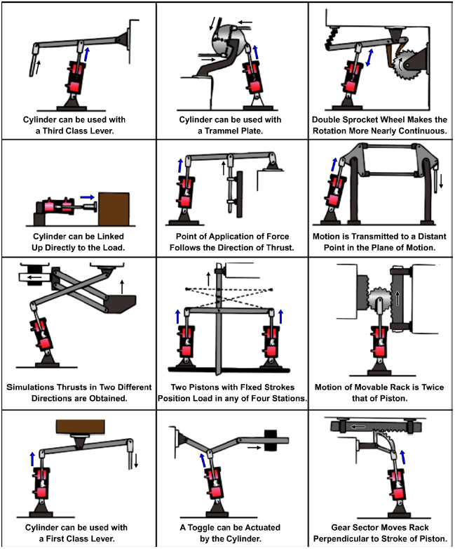
In addition to its versatility, the cylinder-type actuator is probably the most trouble-free component of fluid power systems. However, it is very important that the cylinder, mechanical linkage, and actuating unit are correctly aligned. Any misalignment will cause excessive wear of the piston, piston rod, and seals. Also, proper adjustment between the piston rod and the actuating unit must be maintained.
Motors
A fluid power motor is a device that converts fluid power energy to rotary motion and force. The function of a motor is opposite that of a pump. However, the design and operation of fluid power motors are very similar to pumps. Therefore, a thorough knowledge of pumps will help you understand the operation of fluid power motors. Motors have many uses in fluid power systems. In hydraulic power drives, pumps and motors are combined with suitable lines and valves to form hydraulic transmissions. The pump, commonly referred to as the A-end, is driven by some outside source, such as an electric motor. The pump delivers fluid to the motor. The motor, referred to as the B-end, is actuated by this flow, and through mechanical linkage conveys rotary motion and force to the work. This type of power drive is used to operate (train and elevate) many of the Navy's guns and rocket launchers. Hydraulic motors are commonly used to operate the wing flaps, radomes, and radar equipment in aircraft. Air motors are used to drive pneumatic tools. Air motors are also used in missiles to convert the kinetic energy of compressed gas into electrical power, or to drive the pump of a hydraulic system.
Fluid motors may be either fixed or variable displacement. Fixed-displacement motors provide constant torque and variable speed. The speed is varied by controlling the amount of input flow. Variable-displacement motors are constructed so that the working relationship of the internal parts can be varied to change displacement. The majority of the motors used in fluid power systems are the fixed-displacement type.
Although most fluid power motors are capable of providing rotary motion in either direction, some applications require rotation in only one direction. In these applications, one port of the motor is connected to the system pressure line and the other port to the return line or exhausted to the atmosphere. The flow of fluid to the motor is controlled by a flow control valve, a two-way directional control valve, or by starting and stopping the power supply. The speed of the motor may be controlled by varying the rate of fluid flow to it.
In most fluid power systems, the motor is required to provide actuation power in either direction. In these applications the ports are referred to as working ports, alternating as inlet and outlet ports. The flow to the motor is usually controlled by either a four-way directional control valve or a variable-displacement pump.
Fluid motors are usually classified according to the type of internal element, which is directly actuated by the flow. The most common types of elements are the gear, vane, and piston. All three of these types are adaptable for hydraulic systems, while only the vane-type is used in pneumatic systems.
Gear-Type Motors
The spur, helical, and herringbone design gears are used in gear-type motors.
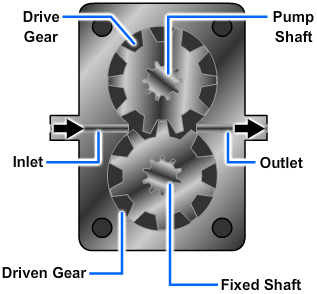
The operation of a gear-type motor is shown in Figure 10-10. Both gears are driven gears; however, only one is connected to the output shaft. As fluid under pressure enters the chamber, it takes the path of least resistance and flows around the inside surface of the housing, forcing the gears to rotate as indicated. The flow continues through the outlet port to the return. This rotary motion of the gears is transmitted through the attached shaft to the work unit.
Vane-Type Motors
A typical vane-type air motor is shown in Figure 10-11. This particular motor provides rotation in only one direction. The rotating element is a slotted rotor which is mounted on a drive shaft. Each slot of the rotor is fitted with a freely sliding rectangular vane. The rotor and vanes are enclosed in the housing, the inner surface of which is offset from the drive shaft axis. When the rotor is in motion, the vanes tend to slide outward due to centrifugal force. The distance the vanes slide is limited by the shape of the rotor housing.
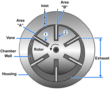
This motor operates on the principle of differential areas. When compressed air is directed into the inlet port, its pressure is exerted equally in all directions. Since area A (Figure 10-11) is greater than area B, the rotor will turn counterclockwise. Each vane, in turn, assumes the No. 1 and No. 2 positions and the rotor turns continuously. The potential energy of the compressed air is thus converted into kinetic energy in the form of rotary motion and force. The air at reduced pressure is exhausted to the atmosphere. The shaft of the motor is connected to the unit to be actuated.
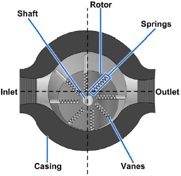
Many vane-type motors are capable of providing rotation in either direction. A motor of this design is shown in Figure 10-12. This motor operates on the same principle as the vane motor shown in Figure 10-11. The two ports may be alternately used as inlet and outlet, thus providing rotation in either direction. Notice the springs in the slots of the rotor. Their purpose is to hold the vanes against the housing during the initial starting of the motor, since centrifugal force does not exist until the rotor begins to rotate.
Piston-Type Motors
Piston-type motors are the most commonly used motors in hydraulic systems. They are basically the same as hydraulic pumps except they are used to convert hydraulic energy into mechanical (rotary) energy.
The most commonly used hydraulic motor is the fixed-displacement piston type. Some equipment uses a variable-displacement piston motor where very wide speed ranges are desired. Although some piston-type motors are controlled by directional control valves, they are often used in combination with variable displacement pumps. This pump-motor combination is used to provide a transfer of power between a driving element and a driven element. Some applications for which hydraulic transmissions may be used are speed reducers, variable speed drives, constant speed or constant torque drives, and torque converters. Some advantages of hydraulic transmission of power over mechanical transmission of power are as follows:
- Quick, easy speed adjustment over a wide range while the power source is operating at a constant (most efficient) speed; rapid, smooth acceleration or deceleration
- Control over maximum torque and power
- Cushioning effect to reduce shock loads
- Smoother reversal of motion
Radial-Piston Motor
The radial-piston motor operates in reverse of the radial-piston pump. In the radial-piston pump, as the cylinder block rotates, the pistons press against the rotor and are forced in and out of the cylinders, thereby receiving fluid and pushing it out into the system. In the radial-piston motor, fluid is forced into the cylinders and drives the pistons outward. The pistons pushing against the rotor cause the cylinder block to rotate.
The operation of a radial-piston motor is shown in Figure 10-13. This motor is shown with three pistons for simplicity. Normally, it contains seven or nine pistons. When liquid is forced into the cylinder bore containing piston 1, the piston moves outward since the liquid cannot be compressed causing the cylinder to rotate in a clockwise direction. As the force acting on piston 1 causes the cylinder block to rotate, piston 2 starts to rotate and approach the position of piston 3 (note that the distance between the cylinder block and the reaction ring of the rotor gets progressively shorter on the top and right half of the rotor).
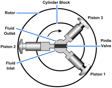
As piston 2 rotates, it is forced inward and, in turn, forces the fluid out of the cylinder. Since there is little or no pressure on this side of the pintle valve, the piston is easily moved in by its contact with the reaction ring of the rotor. The fluid is easily forced out of the cylinder and back to the reservoir or to the inlet side of the pump. As the piston moves past the midpoint or past the shortest distance between the cylinder block and the rotor, it enters the pressure side of the pintle valve and fluid is forced into the cylinder. Piston 3 then becomes the pushing piston and in turn rotates the cylinder block. This action continues as long as fluid under pressure enters the cylinders.
The direction of rotation of the motor (Figure 10-13) is changed by reversing the flow of fluid to it. By admitting fluid under pressure on the top side of the pintle valve, it forces piston 3 out of the cylinder block, causing the cylinder to rotate in the counterclockwise direction.
Axial-Piston Motor
The variable-stroke axial-piston pump usually has either seven or nine single-acting pistons which are evenly spaced around a cylinder barrel. An uneven number of pistons are always used in order to avoid pulsations in the discharge flow. Notice that the term "cylinder barrel," as used here, actually refers to a cylinder block which holds all the cylinders. The piston rods make a ball-and-socket connection with a socket ring. The socket ring rides on a thrust bearing carried by a casting called the tilting box or tilting block.
When the tilting box is at a right angle to the shaft, and the pump is rotating, the pistons do not reciprocate; therefore, no pumping takes place. When the box is tilted away from a right angle, however, the pistons reciprocate and the liquid is pumped.
The variable-stroke axial-piston pump (Figure 10-14) is often used as a part of a variable speed gear such as electrohydraulic anchor windlasses, cranes, winches, and the power-transmitting unit in electrohydraulic steering engines. In those cases, the tilting box is so arranged that it may be tilted in either direction. Thus it may be used to transmit power hydraulically to pistons or rams, or it may be used to drive a hydraulic motor. In the latter use, the pump is driven by a constant-speed electric motor and is called the A-end of the variable speed gear. The hydraulic motor is called the B-end.
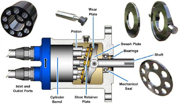
The B-end unit of the hydraulic speed gear is exactly the same as the A-end of the variable-stroke pump mentioned previously. However, it generally does not have a variable-stroke feature. The tilting box is installed at a permanently fixed angle. Thus, the B-end becomes a fixed-stroke axial-piston pump. Figure 10-14 illustrates an axial-piston hydraulic gear with the A-end and B-end as a single unit. It is used in turrets for train and elevation driving units. For electrohydraulic winches and cranes, the A-end and B-end are in separate housings connected by hydraulic piping.
Hydraulic fluid introduced under pressure to a cylinder causes the piston to be pushed out. In being pushed out, the piston, through its connecting rod, will seek the point of greatest distance between the cylinder barrel and the socket ring. The resultant pressure of the piston against the socket ring will cause the cylinder barrel and the socket ring to rotate. This action occurs during the half revolution while the piston is passing the intake port of the motor, which is connected to the pressure port of the pump. After the piston of the motor has taken all the hydraulic fluid it can from the pump, the piston passes the valve plate land and starts to discharge oil through the outlet ports of the motor to the suction inlet of the pump, and thence to suction pistons of the pump. The pump is constantly putting pressure on one side of the motor while it is constantly receiving hydraulic fluid from the other side. The fluid is merely circulated from pump to motor and back again.
Turbines
Turbines are used in pneumatic systems to convert kinetic energy of gases to mechanical energy. Turbines are used to drive electric generators, convert mechanical energy into electrical energy, and drive pumps to supply fluid flow in hydraulic systems.
The basic parts of a turbine are the rotor, which has blades projecting radially from its periphery; and nozzles, through which the gas is expanded and directed. The conversion of kinetic energy to mechanical energy occurs on the blades.
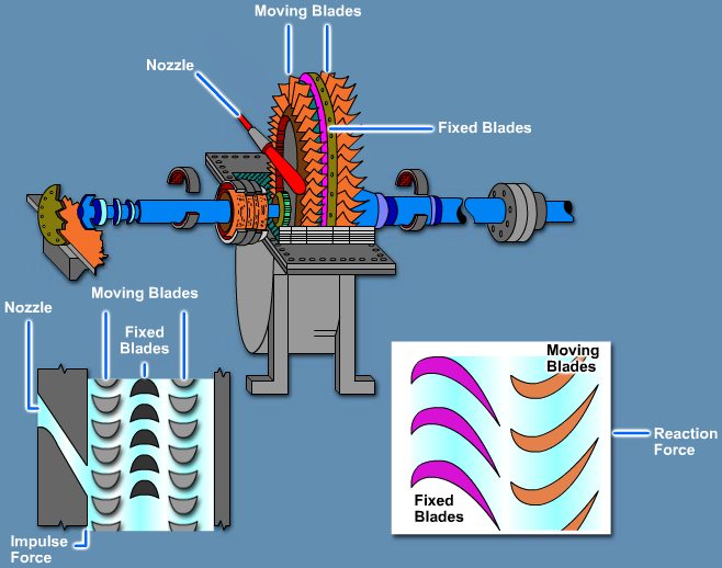
The basic distinction between types of turbines is the manner in which the gas causes the turbine rotor to move. When the rotor is moved by a direct push or impulse from the gas impinging upon the blades, the turbine is said to be an impulse turbine. When the rotor is moved by force of reaction, the turbine is said to be a reaction turbine.
Although the distinction between impulse turbines and reaction turbines is a useful one, it should not be considered as an absolute distinction in real turbines. An impulse turbine uses both the impulse of the gas jet and, to a lesser extent, the reactive force that results when the curved blades cause the gas to change direction. A reaction turbine is moved primarily by reactive force, but some motion of the rotor is caused by the impact of the gas against the blades.
Impulse Turbine
The impulse turbine consists essentially of a rotor mounted on a shaft that is free to rotate in a set of bearings. The outer rim of the rotor carries a set of curved blades, and the whole assembly is enclosed in an airtight case. Nozzles direct the rapidly moving fluid against the blades and turn the rotor.
The steam in an impulse turbine (1) passes through stationary nozzles, which (2) converts some of the thermal energy contained in the steam (indicated by its pressure and temperature) into kinetic energy (velocity), and (3) directs the steam flow into the blades of the turbine wheel (Figure 10-15). The blades and moving wheel (4) then convert the kinetic energy of the steam into mechanical energy in the form of the actual movement of the turbine wheel and shaft or rotor. Let us see why an impulse turbine uses a certain amount of reactive force as opposed to operating purely on the principle of impulse.
Reaction Turbine
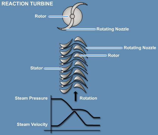
The reaction turbine, as the name implies, is turned by reactive force rather than by a direct push or impulse. In reaction turbines, there are no nozzles as such. Instead, the blades that project radially from the periphery of the rotor are formed and mounted so that the spaces between the blades have, in cross section, the shape of nozzles. Since these blades are mounted on the revolving rotor, they are called moving blades.
In a reaction turbine, steam passes through a row of fixed blades that act as nozzles and expand the steam (decrease pressure). This action increases the steam's velocity and directs it into the moving blades, which are almost identical in shape to the fixed blades (Figure 10-16). Until the steam flows into the moving blades, it is only an impulse turbine. However, the moving blades act as nozzles. More thermal energy of the steam will be converted into kinetic energy, and the steam will counteract or kick back onto the moving blades, giving them−and the wheel to which they are attached−more energy. This conversion is the reason there is a drop (Figure 10-16) in both pressure and velocity across the moving blades of the reaction turbine as opposed to a drop in velocity alone in the impulse turbine. The additional pressure drop across the moving blades provides additional energy (reaction principle) that can be put to work. Consider the principles of both the impulse turbine and the reaction turbine we have described. By changing the direction of the steam flow in the impulse turbine blades, an additional amount of energy is gained (reaction principle).
PDH Classroom offers a continuing education course based on this hydraulic actuators reference page. This course can be used to fulfill PDH credit requirements for maintaining your PE license.
Now that you've read this reference page, earn credit for it!
