Chapter 6: Valves
This page provides the chapter on hydraulic valves from the U.S. Navy's fluid power training course, NAVEDTRA 14105A, "Fluid Power," Naval Education and Training Professional Development and Technology Center, July 2015.
Other related chapters from the Navy's fluid power training course can be seen to the right.
Valves
It is all but impossible to design a practical fluid power system without some means of controlling the volume and pressure of the fluid and directing the flow of fluid to the operating units. This is accomplished by the incorporation of different types of valves. A valve is defined as any device by which the flow of fluid may be started, stopped, or regulated by a movable part that opens or obstructs passage. As applied in fluid power systems, valves are used for controlling the flow, the pressure, and the direction of the fluid flow.
Valves must be accurate in the control of fluid flow and pressure and the sequence of operation. Leakage between the valve element and the valve seat is reduced to a negligible quantity by precision-machined surfaces, resulting in carefully controlled clearances. This is one of the very important reasons for minimizing contamination in fluid power systems. Contamination causes valves to stick, plugs small orifices, and causes abrasions of the valve seating surfaces, which results in leakage between the valve element and valve seat when the valve is in the closed position. Any of these can result in inefficient operation or complete stoppage of the equipment.
Valves may be controlled manually, electrically, pneumatically, mechanically, hydraulically, or by combinations of two or more of these methods. Factors that determine the method of control include the purpose of the valve, the design and purpose of the system, the location of the valve within the system, and the availability of the source of power.
Learning Objectives
When you have completed this chapter, you will be able to do the following:
- Identify the functions of valves in a fluid power system.
- Recognize the functions and operating characteristics of flow control valves.
- Identify the construction features of the various types of flow control valves.
- Recognize the operation and function requirements of pressure control devices for fluid power systems.
- Identify the construction characteristics of pressure control devices for fluid power systems.
- Recognize the construction features of the various types of directional control valves.
- Identify the operating characteristics of directional control valves.
- Identify the uses of various types of directional control valves.
Classifications
Valves are classified according to their use: flow control, pressure control, and directional control. Some valves have multiple functions that fall into more than one classification.
Flow Control Valves
Flow control valves are used to regulate the flow of fluids in fluid-power systems. Control of flow in fluid-power systems is important because the rate of movement of fluid-powered machines depends on the rate of flow of the pressurized fluid. These valves may be manually, hydraulically, electrically, or pneumatically operated. Some of the different types of flow control valves are discussed in the following paragraphs.
Stop Valves
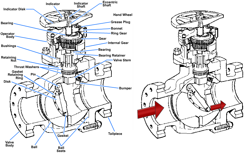
Stop valves are used to shut off or, in some cases, control the flow of fluid. They are controlled by the movement of the valve stem. Stop valves can be divided into four general categories: globe, gate, butterfly, and ball. (Plug valves and needle valves are also considered to be stop valves). An example of a typical ball valve is shown in Figure 6-1.
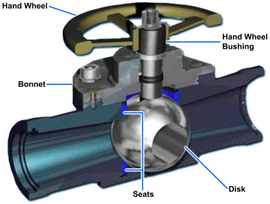
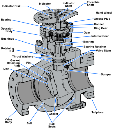
Most ball valves are the quick-acting type. They require only a 90-degree turn to either completely open or close the valve. However, many are operated by planetary gears. This type of gearing allows the use of a relatively small handwheel and limited operating force to operate a fairly large valve. The gearing does, however, increase the operating time for the valve. Some ball valves also contain a swing check located within the ball to give the valve a check valve feature. A ball-stop, swing-check valve with a planetary gear operation is shown in Figure 6-2.
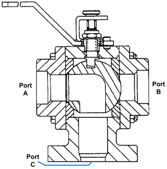
In addition to the ball valves shown in Figures 6-1 and 6-2, there are three-way ball valves that are used to supply fluid from a single source to one component or the other in a two-component system (Figure 6-3).
Gate Valves
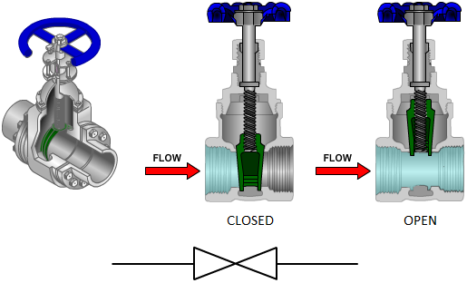
Gate valves are used when a straight-line flow of fluid and minimum flow restriction are needed. Gate valves are so-named because the part that either stops or allows flow through the valve acts somewhat like a gate. The gate is usually wedge-shaped. When the valve is wide open the gate is fully drawn up into the valve bonnet. This leaves an opening for flow through the valve the same size as the pipe in which the valve is installed (Figure 6-4). Therefore, there is little pressure drop or flow restriction through the valve.
Gate valves are not suitable for throttling purposes. The control of flow is difficult because of the valve's design, and the flow of fluid slapping against a partially open gate can cause extensive damage to the valve. Except as specifically authorized, gate valves should not be used for throttling.
Gate valves are classified as either rising-stem or non-rising-stem valves (Figure 6-4). In the design of the rising-stem valve, the stem is attached to the gate. The gate and stem rise and sink together as the valve is operated.
Except as specifically authorized, gate valves should not be used for throttling.
In the design of the non-rising-stem gate valve, the stem is threaded on the lower end into the gate. As the handwheel on the stem is rotated, the gate travels up or down the stem on the threads while the stem remains vertically stationary. This type of valve will almost always have a pointer type of indicator threaded onto the upper end of the stem to indicate the position of the gate inside the valve.
Globe Valves
Globe valves are probably the most common valves in existence. The globe valve gets its name from the globular shape of the valve body. Other types of valves may also have globular-shaped bodies. Thus, it is the internal structure of the valve that identifies this type of valve (Figure 6-5).
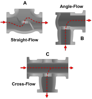
The inlet and outlet openings for globe valves are arranged in a way to satisfy the flow requirements. Straight-, angle-, and cross-flow valves are shown in Figure 6-5.
The moving parts of a globe valve consist of the disk, the valve stem, and the handwheel. The stem connects the handwheel and the disk. It is threaded and fits into the threads in the valve bonnet.
The part of the globe valve that controls flow is the disk, which is attached to the valve stem (disks are available in various designs). The valve is closed by turning the valve stem in until the disk is seated into the valve seat. This prevents fluid from flowing through the valve (Figure 6-6). The edge of the disk and the seat are very accurately machined so that they form a tight seal when the valve is closed. When the valve is open, the fluid flows through the space between the edge of the disk and the seat. Since the fluid flows equally on all sides of the center of support when the valve is open, there is no unbalanced pressure on the disk to cause uneven wear. The rate at which fluid flows through the valve is regulated by the position of the disk in relation to the seat. The valve is commonly used as a fully open or fully closed valve, but it may be used as a throttle valve. However, since the seating surface is a relatively large area, it is not suitable as a throttle valve, where fine adjustments are required in controlling the rate of flow.
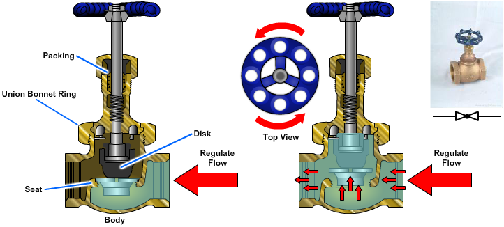
The globe valve should never be jammed in the open position. After a valve is fully opened, the handwheel should be turned toward the closed position approximately one-quarter turn. Unless this is done, the valve is likely to seize in the open position, making it difficult, if not impossible, to close the valve. Many valves are damaged in this manner. Another reason for not leaving globe valves in the fully open position is that it is sometimes difficult to determine if the valve is open or closed. If the valve is jammed in the open position, the stem may be damaged or broken by someone who thinks the valve is closed, and attempts to open it.
It is important that globe valves be installed with the pressure against the face of the disk to keep the system pressure away from the stem packing when the valve is shut.
Butterfly Valves
The butterfly valve is light in weight and is relatively small and quick acting. Butterfly valves are used in freshwater, fuel, lube oil, and chilled water systems where quick action and positive flow control are required (Figure 6-7, view A). Butterfly valves operate in the same manner as the throttle valves and the choke valves in carburetors. A disk attached to a shaft pivots between the open and closed positions as the shaft is turned.
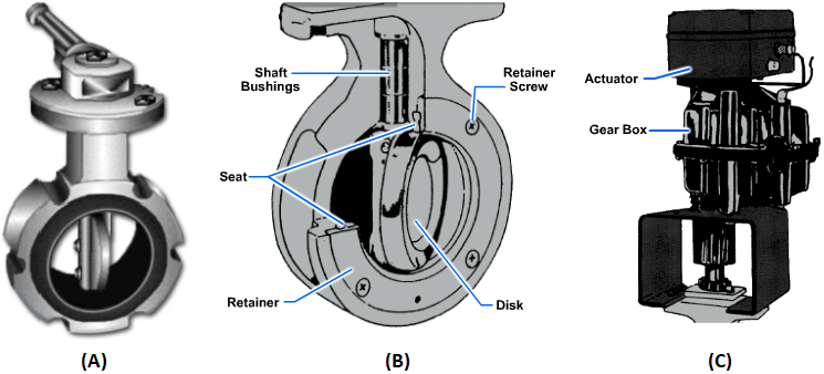
This older design of the butterfly valve is still widely used. This valve provides for positive shutoff, but it should not be used for throttling as standard practice. It consists of a body, a resilient seat, a butterfly-type disk, a stem, packing, a notched positioning plate, and a handle. The seat is under compression when it is installed in the valve body. This design provides a seal for the disk and the upper and lower points where the stem passes through the seat. The packing provides a positive seal around the stem for added protection in case the seal formed by the seat becomes damaged. To gain access to the seat for replacement, you must first remove the stem and valve disk.
A newer, high-performance butterfly valve is shown in Figure 6-7, view B. This improved design has higher pressure capabilities and allows for a full range of throttling positions not offered in the older design of butterfly valves. The newer design of butterfly valve has been introduced into the fleet and is gradually replacing the older design. Unlike the older style of butterfly valve, the new style has a removable retaining ring that holds the seat in place. To change the seat, all you must do is remove the retaining ring, remove the old seat, place a new seat into its groove, and reinstall the retainer ring.
To open or close a butterfly valve, turn the handle only one quarter of a turn to rotate the disk 90 degrees. Some larger butterfly valves may have handwheels or actuators that are driven by pneumatic, electric, or hydraulic means through a gearing arrangement (Figure 6-7, view C).
Needle Valves
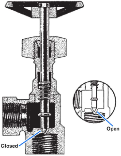
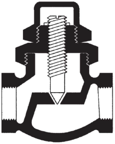
Needle valves are similar in design and operation to the globe valve. Instead of a disk, a needle valve has a long tapered point at the end of the valve stem. A cross-sectional view of a needle valve is illustrated in Figure 6-8.
The long taper of the valve element permits a much smaller seating surface area than that of the globe valve; therefore, the needle valve is more suitable as a throttle valve. Needle valves are used to control flow into delicate gauges, which might be damaged by sudden surges of fluid under pressure. Needle valves are also used to control the end of a work cycle, where it is desirable for motion to be brought slowly to a halt, and at other points where precise adjustments of flow are necessary and where a small rate of flow is desired.
Although many of the needle valves used in fluid power systems are the manually operated type (Figure 6-8), modifications of this type of valve are often used as variable restrictors. This valve is constructed without a handwheel and is adjusted to provide a specific rate of flow. This rate of flow will provide a desired time of operation for a particular subsystem. Since this type of valve can be adjusted to conform to the requirements of a particular system, it can be used in a variety of systems. A needle valve that was modified as a variable restrictor is illustrated in Figure 6-9.
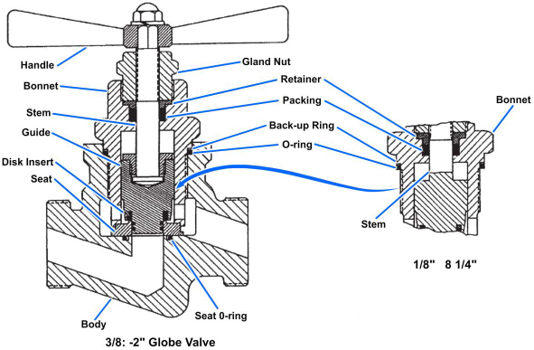
Hydraulic and Pneumatic Globe Valves
The valve consists of a valve body and a stem cartridge assembly. The stem cartridge assembly includes the bonnet, gland nut, packing, packing retainer, handle, stem, and seat. On small valves (1/8 and 1/4 inch) the stem is made in one piece, but on larger sizes it is made of a stem, guide, and stem retainer. The valve disk is made of nylon and is swaged into either the stem, for 1/8- and 1/4-inch valves, or the guide, for larger valves. The bonnet screws into the valve body with left-hand threads and is sealed by an O-ring (including a back-up ring).
The valve is available with either a rising stem or a non-rising stem. The rising stem valve uses the same port body design as does the non-rising stem valve. The stem is threaded into the gland nut and screws outward as the valve is opened.
This valve does not incorporate provisions for tightening the stem packing nor replacing the packing while the valve is in service; therefore, complete valve disassembly is required for maintenance. A rising stem hydraulic and pneumatic globe valve is illustrated in Figure 6-10.
Special-Purpose Valves
The safe and efficient operation of fluid power systems, system components, and related equipment requires a means of controlling pressure. There are many types of automatic pressure control valves. Some of them merely provide an escape for pressure that exceeds a set limit; some only reduce the pressure to a lower pressure system or subsystem; and some keep the pressure in a system within a required range.
Relief Valves
Some fluid power systems, even when operating normally, may temporarily develop excessive pressure; for example, when an unusually strong work resistance is encountered. Relief valves are used to control this excess pressure.
Relief valves are automatic valves used on system lines and equipment to prevent overpressurization. Most relief valves simply lift (open) at a preset pressure and reset (shut) when the pressure drops slightly below the lifting pressure. Relief valves do not maintain flow or pressure at a given amount, but prevent pressure from rising above a specific level when the system is temporarily overloaded.
Main system relief valves are generally installed between the pump or pressure source and the first system isolation valve. The valve must be large enough to allow the full output of the hydraulic pump to be delivered back to the reservoir. In a pneumatic system, the relief valve controls excess pressure by discharging the excess gas to the atmosphere.
Smaller relief valves, similar in design and operation to the main system relief valve, are often used in isolated parts of the system where a check valve or directional control valve prevents pressure from being relieved through the main system relief valve and where pressures must be relieved at a set point lower than that provided by the main system relief. These small relief valves are also used to relieve pressures caused by thermal expansion (see glossary) of the fluids.
A typical relief valve is shown in Figure 6-11. System pressure acts on the valve disk at the inlet to the valve. When the system pressure exceeds the force exerted by the valve spring, the valve disk lifts off of its seat, allowing some of the system fluid to escape through the valve outlet until the system pressure is reduced to just below the relief set point of the valve.
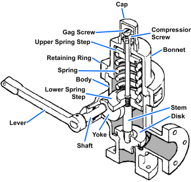
All relief valves have an adjustment for increasing or decreasing the set relief pressure. Some relief valves are equipped with an adjusting screw for this purpose. This adjusting screw is usually covered with a cap, which must be removed before an adjustment can be made. Some type of locking device, such as a lock nut, is usually provided to prevent the adjustment from changing through vibration. Other types of relief valves are equipped with a handwheel for making adjustments to the valve. Either the adjusting screw or the handwheel is turned clockwise to increase the pressure at which the valve will open. In addition, most relief valves are also provided with an operating lever or some type of device to allow manual cycling or gagging the valve open for certain tasks.
The relief valve shown in Figure 6-11 is used to efficiently serve the requirements of some fluid power systems; however, this relief valve is unsatisfactory for some applications. To give you a better understanding of the operation of relief valves, we will discuss some of the undesirable characteristics of this valve.
A simple relief valve, such as the one illustrated in Figure 6-11, with a suitable spring adjustment can be set so that it will open when the system pressure reaches a certain level, 500 pounds per square inch (psi) for example. When the valve does open, the volume of flow to be handled may be greater than the capacity of the valve; therefore, pressure in the system may increase to several hundred psi above the set pressure before the valve brings the pressure under control. A simple relief valve will be effective under these conditions only if it is very large. In this case, it would operate stiffly and the valve element would chatter back and forth. In addition, the valve will not close until the system pressure decreases to a point somewhat below the opening pressure.
The surface area of the valve element must be larger than that of the pressure opening if the valve is to seat satisfactorily, as shown in Figure 6-12. The pressure in the system acts on the valve element to open to it. In each case, the force exerted directly upward by system pressure when the valve is closed depends on the area (Figure 6-12, area A) across the valve element where the element seats against the pressure tube. The moment the valve opens, however, the upward force exerted depends on the horizontal area (Figure 6-12, area B) of the entire valve element, which is greater than area in Figure 6-12, area A. This force causes an upward jump of the valve element immediately after it opens, because the same pressure acting over different areas produces forces proportional to the areas. It also requires a greater force to close the valve than was required to open it. As a result, the valve will not close until the system pressure has decreased to a certain point below the pressure required to open it.
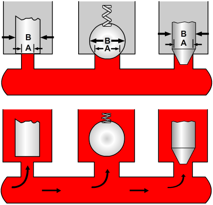
Let us assume that a valve of this type is set to open at 500 psi. When the valve is closed, the pressure acts on the area in Figure 6-12, area A. If this area is 0.5 square inch, an upward force of 250 pounds (500 x 0.5) will be exerted on the valve at the moment of opening. With the valve open, however, the pressure acts on the area in Figure 6-12, area B. If the area in Figure 6-12, area B is 1 square inch, the upward force is 500 pounds, or double the force at which the valve actually opened.
For the valve to close, pressure in the system would have to decrease well below the point at which the valve opened. The exact pressure would depend on the shape of the valve element.
In some hydraulic systems, there is pressure in the return line. This back pressure is caused by restrictions in the return line and will vary in relation to the amount of fluid flowing in the return line. This pressure creates a force on the back of the valve element and will increase the force necessary to open the valve and relieve system pressure.
Simple relief valves have a tendency to open and close rapidly as they "hunt" above and below the set pressure, causing pressure pulsations and undesirable vibrations and producing a noisy chatter. Because of the unsatisfactory performance of the simple relief valve in some applications, compound relief valves were developed.
Compound relief valves use the principles of operation of simple relief valves for one stage of their action—that of the pilot valve. Provision is made to limit the amount of fluid that the pilot valve must handle, and thereby avoid the weaknesses of simple relief valves. (A pilot valve is a small valve used for operating another valve.)
The operation of a compound relief valve is illustrated in Figure 6-13. In Figure 6-13, view A, the main valve, which consists of a piston, stem, and spring, is closed, blocking flow from the high pressure line to the reservoir. Fluid in the high pressure line flows around the stem of the main valve as it flows to the actuating unit. The stem of the main valve is hollow (the stem passage) and contains the main valve spring, which forces the main valve against its seat. When the pilot valve is open the stem passage allows fluid to flow from the pilot valve, around the main valve spring, and down to the return line.

There is also a narrow passage (piston passage) through the main valve piston. This passage connects the high pressure line to the valve chamber.
The pilot valve is a small, ball-type, springloaded check valve, which connects the top of the passage from the valve chamber with the passage through the main valve stem. The pilot valve is the control unit of the relief valve because the pressure at which the relief valve will open depends on the tension of the pilot valve spring. The pilot valve spring tension is adjusted by turning the adjusting screw so that the ball will unseat when system pressure reaches the preset limit.
Fluid at line pressure flows through the narrow piston passage to fill the chamber. Because the line and the chamber are connected, the pressure in both are equal. The top and bottom of the main piston have equal areas; therefore, the hydraulic forces acting upward and downward are equal, and there is no tendency for the piston to move in either direction. The only other force acting on the main valve is that of the main valve spring, which holds it closed.
When the pressure in the high pressure line increases to the point at which the pilot valve is set, the ball unseats (Figure 6-13, view B). This opens the valve chamber through the valve stem passage to the low pressure return line. Fluid immediately begins to flow out of the chamber, much faster than it can flow through the narrow piston passage. As a result the chamber pressure immediately drops, and the pilot valve begins to close again, restricting the outward flow of fluid. Chamber pressure therefore increases, the valve opens, and the cycle repeats.
So far, the only part of the valve that has moved appreciably is the pilot, which functions just like any other simple spring-loaded relief valve. Because of the small size of the piston passage, there is a severe limit on the amount of overpressure protection the pilot can provide the system. All the pilot valve can do is limit fluid pressure in the valve chamber above the main piston to a preset maximum pressure, by allowing excess fluid to flow through the piston passage, through the stem passage, and into the return line. When pressure in the system increases to a value that is above the flow capacity of the pilot valve, the main valve opens, permitting excess fluid to flow directly to the return line. This is accomplished in the following manner.
As system pressure increases, the upward force on the main piston overcomes the downward force, which consists of the tension of the main piston spring and the pressure of the fluid in the valve chamber (Figure 6-13, view C). The piston then rises, unseating the stem, and allows the fluid to flow from the system pressure line directly into the return line. This causes system pressure to decrease rapidly, since the main valve is designed to handle the complete output of the pump. When the pressure returns to normal, the pilot spring forces the ball onto the seat. Pressures are equal above and below the main piston, and the main spring forces the valve to seat.
As you can see, the compound valve overcomes the greatest limitation of a simple relief valve by limiting the flow through the pilot valve to a quantity it can satisfactorily handle. This limits the pressure above the main valve and enables the main line pressure to open the main valve. In this way, the system is relieved when an overload exists.
Pressure Regulators
Pressure regulators, often referred to as unloading valves, are used in fluid power systems to regulate pressure. In pneumatic systems, the valve, commonly referred to as a pressure regulator, simply reduces pressure. This type of valve is discussed later in this chapter under pressure-reducing valves. In hydraulic systems the pressure regulator is used to unload the pump and to maintain and regulate system pressure at the desired values. All hydraulic systems do not require pressure regulators. The open-center system does not require a pressure regulator. Many systems are equipped with variable-displacement pumps, which contain a pressure-regulating device.
Pressure regulators are made in a variety of types and by various manufacturers; however, the basic operating principles of all regulators are similar to the one illustrated in Figure 6-14.
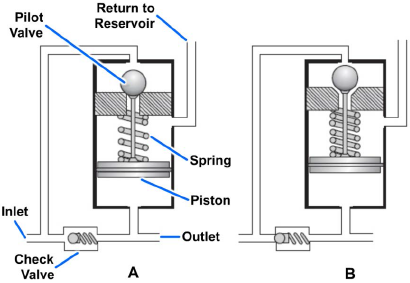
A regulator is open when it is directing fluid under pressure into the system (Figure 6-14, view A). In the closed position (Figure 6-14, view B), the fluid in the part of the system beyond the regulator is trapped at the desired pressure, and the fluid from the pump is bypassed into the return line and back to the reservoir. To prevent constant opening and closing (chatter), the regulator is designed to open at a pressure somewhat lower than the closing pressure. This difference is known as differential or operating range. For example, assume that a pressure regulator is set to open when the system pressure drops below 600 psi, and close when the pressure rises above 800 psi. The differential or operating range is 200 psi.
Assume that the piston has an area of 1 square inch (Figure 6-14), the pilot valve has a cross-sectional area of 1/4 square inch, and the piston spring provides 600 pounds of force pushing the piston down. When the pressure in the system is less than 600 psi, fluid from the pump will enter the inlet port, flow to the top of the regulator, and then to the pilot valve. When the pressure of the fluid at the inlet increases to the point where the force it creates against the front of the check valve exceeds the force created against the back of the check valve by system pressure and the check valve spring, the check valve opens. This allows fluid to flow into the system and to the bottom of the regulator against the piston. When the force created by the system pressure exceeds the force exerted by the spring, the piston moves up, causing the pilot valve to unseat. Since the fluid will take the path of least resistance, it will pass through the regulator and back to the reservoir through the return line.
When the fluid from the pump is suddenly allowed a free path to return, the pressure on the input side of the check valve drops and the check valve closes. The fluid in the system is then trapped under pressure. This fluid will remain pressurized until a power unit is actuated, or until pressure is slowly lost through normal internal leakage within the system.
When the system pressure decreases to a point slightly below 600 psi, the spring forces the piston down and closes the pilot valve. When the pilot valve is closed, the fluid cannot flow directly to the return line. This causes the pressure to increase in the line between the pump and the regulator. This pressure opens the check valve, causing the fluid to enter the system.
In summary, when the system pressure decreases a certain amount, the pressure regulator will open, sending fluid to the system. When the system pressure increases sufficiently, the regulator will close, allowing the fluid from the pump to flow through the regulator and back to the reservoir. The pressure regulator takes the load off of the pump and regulates system pressure.
Sequence Valves
Sequence valves control the sequence of operation between two branches in a circuit; that is, they enable one unit to automatically set another unit into motion. An example of the use of a sequence valve is in an aircraft landing gear actuating system.
In a landing gear actuating system, the landing gear doors must open before the landing gear starts to extend. Conversely, the landing gear must be completely retracted before the doors close. A sequence valve installed in each landing gear actuating line performs this function.
A sequence valve is somewhat similar to a relief valve except that, after the set pressure has been reached, the sequence valve diverts the fluid to a second actuator or motor to do work in another part of the system. An installation of two sequence valves that control the sequence of operation of three actuating cylinders is shown in Figure 6-15. Fluid is free to flow into cylinder A. The first sequence valve (1) blocks the passage of fluid until the piston in cylinder A moves to the end of its stroke. At this time, sequence valve 1 opens, allowing fluid to enter cylinder B. This action continues until all three pistons complete their strokes.
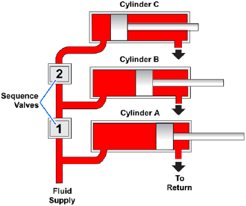
There are various types of sequence valves. Some are controlled by pressure and some are controlled mechanically.
Pressure-Controlled Sequence Valves
The operation of a typical pressure-controlled sequence valve is illustrated in Figure 6-16. The opening pressure is obtained by adjusting the tension of the spring that normally holds the piston in the closed position.
The top part of the piston has a larger diameter than the bottom part.
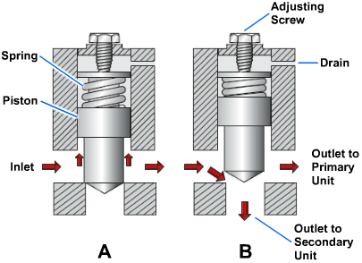
Fluid enters the valve through the inlet port, flows around the lower part of the piston and exits the outlet port, where it flows to the primary (first) unit to be operated (Figure 6-16, view A). This fluid pressure also acts against the lower surface of the piston.
When the primary actuating unit completes its operation, pressure in the line to the actuating unit increases sufficiently to overcome the force of the spring, and the piston rises. The valve is then in the open position (Figure 6-16, view B). The fluid entering the valve takes the path of least resistance and flows to the secondary unit.
A drain passage is provided to allow any fluid leaking past the piston to flow from the top of the valve. In hydraulic systems, this drain line is usually connected to the main return line.
Mechanically Operated Sequence Valves
The mechanically operated sequence valve (Figure 6-17) is operated by a plunger that extends through the body of the valve. The valve is mounted so that the plunger will be operated by the primary unit.
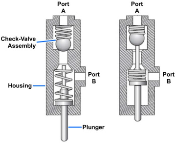
A check valve, either a ball or a poppet, is installed between the fluid ports in the body. It can be unseated by either the plunger or fluid pressure.
Port A (Figure 6-17) and the actuator of the primary unit are connected by a common line. Port B is connected by a line to the actuator of the secondary unit. When fluid under pressure flows to the primary unit, it also flows into the sequence valve through port A to the seated check valve in the sequence valve. In order to operate the secondary unit, the fluid must flow through the sequence valve. The valve is located so that the primary unit depresses the plunger as it completes its operation. The plunger unseats the check valve and allows the fluid to flow through the valve, out port B, and to the secondary unit.
This type of sequence valve permits flow in the opposite direction. Fluid enters port B and flows to the check valve. Although this is return flow from the actuating unit, the fluid overcomes spring tension, unseats the check valve, and flows out through port A.
Pressure-Reducing Valves
Pressure-reducing valves provide a steady pressure into a system that operates at a lower pressure than the supply system. A reducing valve can normally be set for any desired downstream pressure within the design limits of the valve. Once the valve is set, the reduced pressure will be maintained regardless of changes in supply pressure (as long as the supply pressure is at least as high as the reduced pressure desired) and regardless of the system load, providing the load does not exceed the design capacity of the reducer.
There are various designs and types of pressure-reducing valves. The spring-loaded reducer and the pilot-controlled valve are discussed in this text.
Spring-Loaded Reducing Valves
The spring-loaded pressure-reducing valve (Figure 6-18) is commonly used in pneumatic systems. It is often referred to as a pressure regulator.
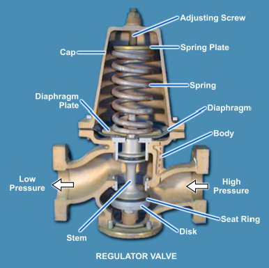
One type of spring-loaded reducing valve is shown in Figure 6-18. These valves are used in a wide variety of applications. Low pressure air reducers, auxiliary machinery cooling-water reducing stations, and some reduced-steam system reducers are of this type. The valve simply uses spring pressure against a diaphragm to open the valve. On the bottom of the diaphragm, the outlet pressure (the pressure in the reduced-pressure system) of the valve forces the disk upward to shut the valve. When the outlet pressure drops below the set point of the valve, spring pressure overcomes the outlet pressure and forces the valve stem downward, opening the valve. As outlet pressure increases, approaching the desired value, the pressure under the diaphragm begins to overcome spring pressure. This forces the valve stem upward, shutting the valve. Downstream pressure can be adjusted by removing the valve cap and turning the adjusting screw, which varies the spring pressure against the diaphragm. This particular spring-loaded valve will fail in the open position in the case of a diaphragm rupture.
Internal Pilot-Actuated Pressure-Reducing Valves
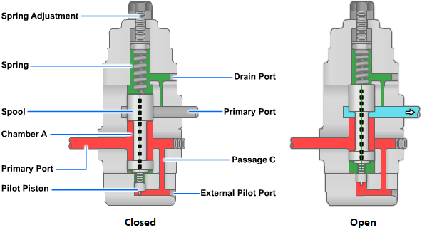
The internal pilot-actuated pressure-reducing valve (Figure 6-19) uses a pilot valve to control the main valve. The pilot valve controls the flow of upstream fluid, which is ported from the pilot valve, to the operating piston, which operates the main valve. The main valve is opened by the operating piston and closed by the main valve spring. The pilot valve opens when the adjusting spring pushes downward on the pilot diaphragm. It closes when downstream pressure exerts a force that exceeds the force of the adjusting spring. When the pilot valve shuts off or throttles the flow of upstream fluid to the operating piston, the main valve then pushes the valve and stem upward to throttle or close the main valve. When downstream pressure falls below the set point, the adjusting spring force acts downward on the diaphragm. This action overcomes the force of the downstream system pressure, which is acting upward on the diaphragm. This opens the pilot valve, allowing upstream pressure to the top of the operating piston to open the main valve.
Pneumatic-Pressure-Controlled Reducing Valves
For engines that use compressed air as a power source, starting air comes directly from the ship's medium or high pressure air service line or from starting air flasks, which are included in some systems for the purpose of storing starting air. From either source, the air, on its way to the engine, must pass through a pressure reducing valve, which reduces the higher pressure to the operating pressure required to start a particular engine.
One type of pressure-reducing valve is the regulator (Figure 6-20), in which compressed air, sealed in a dome, furnishes the regulating pressure that actuates the valve. The compressed air in the dome performs the same function as a spring used in a more common type of regulating valve. The dome is tightly secured to the valve body, which is separated into an upper (low pressure outlet) and a lower (high pressure inlet) chamber by the main valve. At the top of the valve stem is another chamber, which contains a rubber diaphragm and a metal diaphragm plate. This chamber has an opening leading to the low pressure outlet chamber. When the outlet pressure drops below the pressure in the dome, air in the dome forces the diaphragm and the diaphragm plate down on the valve stem. This partially opens the valve and permits high pressure air to pass the valve seat into the low pressure outlet and into the space under the diaphragm. As soon as the pressure under the diaphragm is equal to that in the dome, the diaphragm returns to its normal position, and the valve is forced shut by the high pressure air acting on the valve head.
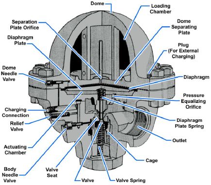
When the dome-type regulator is used in the air start system for a diesel engine during the starting event, the regulator valve continuously and rapidly adjusts for changes in air pressure by partially opening and partially closing to maintain a safe, constant starting pressure. When the engine starts and there is no longer a demand for air, pressure builds up in a low pressure chamber to equal the pressure in the dome, and the valve closes completely.
Pilot-Controlled Pressure-Reducing Valves
The operation of a pilot-controlled pressure-reducing valve is illustrated in Figure 6-21. This valve consists of an adjustable pilot valve, which controls the operating pressure of the valve, and a spool valve, which reacts to the action of the pilot valve.
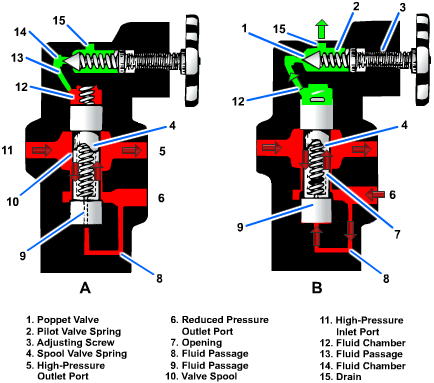
The pilot valve consists of a poppet (1), a spring (2), and an adjusting screw (3). The valve spool assembly consists of a valve spool (10) and a spring (4).
Fluid under main pressure enters the inlet port (11) and under all conditions is free to flow through the valve and the outlet port (5). (Either port (5) or port (11) may be used as the high pressure port.)
The valve in the open position is shown in Figure 6-21, view A. In the open position, the pressure in the reduced-pressure outlet port (6) has not reached the preset operating pressure of the valve. The fluid also flows through passage (8), through smaller passage (9) in the center of the valve spool, and into chamber (12). The fluid pressure at outlet port (6) is therefore distributed to both ends of the spool. When these pressures are equal the spool is hydraulically balanced. Spring (4) is a low-tension spring and applies only a slight downward force on the spool. Its main purpose is to position the spool and to maintain opening (7) at its maximum size.
As the pressure increases in outlet port (6) (Figure 6-21, view B), this pressure is transmitted through passages (8) and (9) to chamber (12). This pressure also acts on the pilot valve poppet (1). When this pressure increases above the preset operating pressure of the valve, it overcomes the force of pilot valve spring (2) and unseats the poppet. This allows fluid to flow through the drain port (15). Because the small passage (9) restricts flow into chamber (12), the fluid pressure in the chamber drops. This causes a momentary difference in pressure across the valve spool (10), which allows fluid pressure acting against the bottom area of the valve spool to overcome the downward force of spring (4). The spool is then forced upward until the pressures across its ends are equalized. As the spool moves upward, it restricts the flow through opening (7) and causes the pressure to decrease in the reduced pressure outlet port (6). If the pressure in the outlet port continues to increase to a value above the preset pressure, the pilot valve will open again and the cycle will repeat. This allows the spool valve to move up higher into chamber (12); thus further reducing the size of opening (7). These cycles repeat until the desired pressure is maintained in outlet (6).
When the pressure in outlet (6) decreases to a value below the preset pressure, spring (4) forces the spool downward, allowing more fluid to flow through opening 7.
Air-Pilot-Operated Diaphragm Control Valves
These valves are used extensively on naval ships. The valves and their control pilots are available in several designs to meet different requirements. They may be used as unloading valves to reduce pressure or to provide continuous regulation of pressure and temperature. They may also be used for the control of liquid levels.
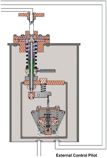
The air-operated control pilot may be either direct acting or reverse acting. A direct-acting pilot is shown in Figure 6-22. In this type of pilot, the controlled pressure—that is, the pressure from the discharge side of the diaphragm control valve — acts on top of a diaphragm in the control pilot. This pressure is balanced by the pressure exerted by the pilot adjusting spring. When the controlled pressure increases and overcomes the pressure exerted by the pilot adjusting spring, the pilot valve stem is forced downward. This action opens the pilot valve to increase the amount of operating air pressure going from the pilot to the diaphragm control valve. A reverse acting pilot has a lever that reverses the pilot action. In a reverse-acting pilot, an increase in controlled pressure produces a decrease in operating air pressure.
In the diaphragm control valve, operating air from the pilot acts on a diaphragm contained in the superstructure of the valve operator or positioner (Figure 6-23). It is direct-acting in some valves and reverse-acting in others. If the valve operator is direct-acting, the operating air pressure from the control pilot is applied to the TOP of the valve diaphragm. When the valve operator is reverse-acting, the operating air pressure from the pilot is applied to the UNDERSIDE of the valve diaphragm.
A very simple type of direct-acting diaphragm control valve is shown in Figure 6-23, views A and B. The operating air pressure from the control pilot is applied to the top of the valve diaphragm. The valve in Figure 6-23, view A is a downward-seating valve. Any increase in operating air pressure pushes the valve stem downward. This tends to close the valve.
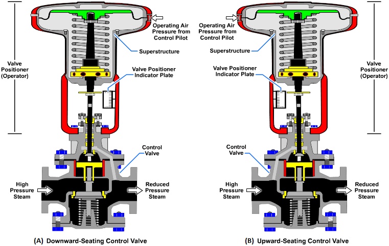
Now look at Figure 6-23, view B; this is also a direct-acting valve. The operating air pressure from the control pilot is applied to the top of the valve diaphragm. The valve in Figure 6-23, view B is an upward-seating valve rather than a downward-seating valve. Therefore, any increase in operating air pressure from the control pilot tends to OPEN this valve rather than to close it.
As we have seen, the air-operated control pilot and the positioner of the diaphragm control valve may be either direct-acting or reverse-acting. In addition, the diaphragm control valve may be either upward-seating or downward-seating. These factors, as well as the purpose of the installation, determine how the diaphragm control valve and its air-operated control pilot are installed in relation to each other.
To see how these factors are related, let's consider an installation; a diaphragm control valve and its air-operated control pilot are used to supply reduced steam pressure (Figure 6-24). We will assume that the service requirements indicate the need for a direct-acting, upward-seating, diaphragm control valve. Can you figure out which kind of a control pilot — direct-acting or reverse-acting — should be used in this installation?
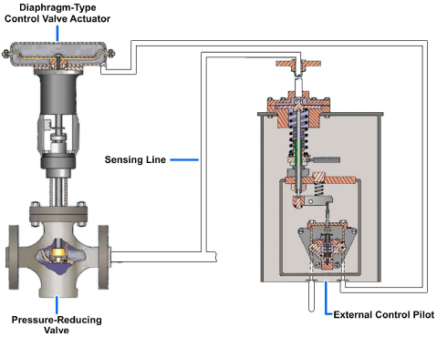
Let's try it first with a direct-acting control pilot. The controlled pressure (discharge pressure from the diaphragm control valve) increases. When that happens, increased pressure is applied to the diaphragm of the direct-acting control pilot. The valve stem is pushed downward and the valve in the control pilot is opened. This sends an increased amount of operating air pressure from the control pilot to the top of the diaphragm control valve. The increased operating air pressure acting on the diaphragm of the valve pushes the stem downward. Since this is an upward-seating valve, this action OPENS the diaphragm control valve still wider. Obviously, this won't work — for this application, an INCREASE in controlled pressure must result in a DECREASE in operating air pressure. Therefore, we made a mistake in choosing the direct-acting control pilot. For this particular pressure-reducing application, we should choose a REVERSE-ACTING control pilot.
You will probably not need to decide which type of control pilot and diaphragm control valve are needed in any particular installation. But you must know how and why they are selected so that you will not make mistakes in repairing or replacing these units.
Remote-Operated Valves
Remote-operating gears provide a means of operating certain valves from distant stations. Remote-operating gears may be mechanical, hydraulic, pneumatic, or electric. A reach rod or series of reach rods and gears may be used to operate engine-room valves in instances where valves are difficult to reach. Two types of remote-operated valves are illustrated in Figure 6-25.
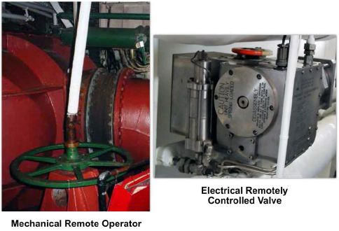
Other remote-operating gear is installed as emergency equipment. Some split-plant valves, main drainage system valves, and overboard valves are equipped with remote-operating gears. These valves can be operated normally or, in an emergency, they may be operated from remote stations. Remote-operating gears also include a valve position indicator to show whether the valve is open or closed.
Counterbalance Valves
The counterbalance valve is normally located in the line between a directional control valve and the outlet of a vertically mounted actuating cylinder which supports weight or must be held in position for a period of time. This valve serves as a hydraulic resistance to the actuating cylinder. For example, counterbalance valves are used in some hydraulically operated forklifts. The valve offers a resistance to the flow from the actuating cylinder when the fork is lowered. It also helps to support the fork in the UP position.
Counterbalance valves are also used in airlaunched weapons loaders. In this case the valve is located in the top of the lift cylinder. The valve requires a specific pressure to lower the load. If adequate pressure is not available, the load cannot be lowered. This prevents collapse of the load due to any malfunction of the hydraulic system.
One type of counterbalance valve is illustrated in Figure 6-26. The valve element is a balanced spool (4). The spool consists of two pistons permanently fixed on either end of a shaft. The inner surface areas of the pistons are equal; therefore, pressure acts equally on both areas regardless of the position of the valve and has no effect on the movement of the valve — hence, the term balanced. The shaft area between the two pistons provides the area for the fluid to flow when the valve is open. A small piston (9) is attached to the bottom of the spool valve.
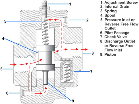
When the valve is in the closed position, the top piston of the spool valve blocks the discharge port (8). With the valve in this position, fluid flowing from the actuating unit enters the inlet port (5). The fluid cannot flow through the valve because discharge port (8) is blocked. However, fluid will flow through the pilot passage (6) to the small pilot piston. As the pressure increases, it acts on the pilot piston until it overcomes the preset pressure of spring (3). This forces the valve spool (4) up and allows the fluid to flow around the shaft of the valve spool and out discharge port (8). Figure 6-26 shows the valve in this position. During reverse flow, the fluid enters port (8). The spring (3) forces valve spool (4) to the closed position. The fluid pressure overcomes the spring tension of the check valve (7). The check valve opens and allows free flow around the shaft of the valve spool and out through port (5).
The operating pressure of the valve can be adjusted by turning the adjustment screw (1), which increases or decreases the tension of the spring. This adjustment depends on the weight that the valve must support.
It is normal for a small amount of fluid to leak around the top piston of the spool valve and into the area around the spring. An accumulation would cause additional pressure on top of the spool valve. This would require additional pressure to open the valve. The drain (2) provides a passage for this fluid to flow to port (8).
Directional Control Valves
Directional control valves are designed to direct the flow of fluid, at the desired time, to the point in a fluid power system where it will do work. The driving of a ram back and forth in its cylinder is an example of when a directional control valve is used. Various other terms are used to identify directional valves, such as selector valve, transfer valve, and control valve. This manual will use the term directional control valve to identify these valves.
Directional control valves for hydraulic and pneumatic systems are similar in design and operation. However, there is one major difference. The return port of a hydraulic valve is ported through a return line to the reservoir, while the similar port of a pneumatic valve, commonly referred to as the exhaust port, is usually vented to the atmosphere. Any other differences are pointed out in the discussion of the valves.
Directional control valves may be operated by differences in pressure acting on opposite sides of the valving element, or they may be positioned manually, mechanically, or electrically. Often two or more methods of operating the same valve will be used in different phases of its action.
Directional control valves may be classified in several ways. Some of the different ways are by the type of control, the number of ports in the valve housing, and the specific function of the valve. The most common method is by the type of valving element used in the construction of the valve. The most common types of valving elements are the ball, cone or sleeve, poppet, rotary spool, and sliding spool. The basic operating principles of the poppet, rotary spool, and sliding spool valving elements are discussed in this text.
Poppet
The poppet fits into the center bore of the seat (Figure 6-27). The seating surfaces of the poppet and the seat are lapped or closely machined so that the center bore will be sealed when the poppet is seated (shut). The action of the poppet is similar to that of the valves in an automobile engine. In most valves the poppet is held in the seated position by a spring.
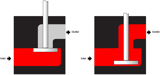
The valve consists primarily of a movable poppet that closes against the valve seat. In the closed position, fluid pressure on the inlet side tends to hold the valve tightly closed. A small amount of movement from a force applied to the top of the poppet stem opens the poppet and allows fluid to flow through the valve.
The use of the poppet as a valving element is not limited to directional control valves.
Rotary Spool Valve
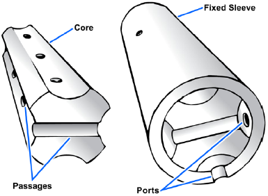
The rotary spool directional control valve (Figure 6-28) has a round core with one or more passages or recesses in it. The core is mounted within a stationary sleeve. As the core is rotated within the stationary sleeve, the passages or recesses connect or block the ports in the sleeve. The ports in the sleeve are connected to the appropriate lines of the fluid system.
Sliding Spool Valve
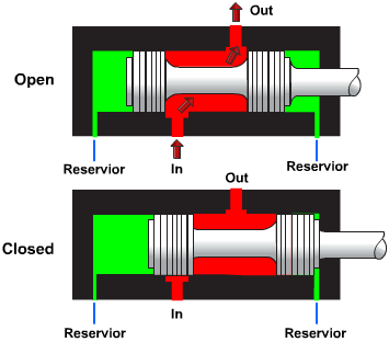
The operation of a simple sliding spool directional control valve is shown in Figure 6-29. The valve is so-named because of the shape of the valving element that slides back and forth to block and uncover portsin the housing. (The sliding element is also referred to as a piston.) The inner piston areas (lands) are equal. Thus fluid under pressure that enters the valve from the inlet ports acts equally on both inner piston areas regardless of the position of the spool. Sealing is usually accomplished by a very closely machined fit between the spool and the valve body or sleeve. For valves with more ports, the spool is designed with more pistons or lands on a common shaft. The sliding spool is the most commonly used type of valving element in directional control valves.
Check Valve
Check valves are used in fluid systems to permit flow in one direction and to prevent flow in the other direction. They are classified as one-way directional control valves. The check valve may be installed independently in a line to allow flow in one direction only, or it may be used as an integral part of globe, sequence, counterbalance, and pressure-reducing valves.
Check valves are available in various designs. They are opened by the force of fluid in motion flowing in one direction, and are closed by fluid attempting to flow in the opposite direction. The force of gravity or the action of a spring aids in closing the valve.
A ball-stop swing-check valve with planetary gear operation is shown in Figure 6-30. Ball valves are normally found in the following systems aboard ship: seawater, sanitary, trim and drain, air, hydraulic, and oil transfer.
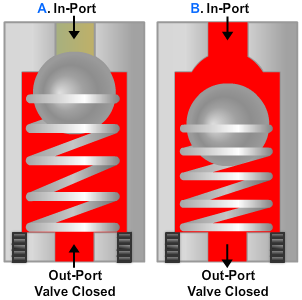
The most common type of check valve installed in fluid-power systems uses either a ball or cone for the sealing element. As fluid pressure is applied in the direction of the arrow the ball is forced off its seat, allowing fluid to flow freely through the valve. This valve is known as a spring-loaded check valve (Figure 6-31).
The spring is installed in the valve to hold the cone or ball on its seat whenever fluid is not flowing. The spring also helps to force the cone or ball on its seat when the fluid attempts to flow in the opposite direction. Since the opening and closing of this type of valve is not dependent on gravity, its location in a system is not limited to the vertical position.
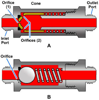
A modification of the spring-loaded check valve is the orifice check valve (Figure 6-32). This valve allows normal flow in one direction and restricted flow in the other. It is often referred to as a one-way restrictor.
A cone-type orifice check valve is shown in Figure 6-32, view A. When sufficient fluid pressure is applied at the inlet port, it overcomes spring tension and moves the cone off of its seat. The two orifices in the illustration represent several openings located around the slanted circumference of the cone. These orifices allow free flow of fluid through the valve while the cone is off of its seat. When fluid pressure is applied through the outlet port, the force of the fluid and spring tension move the cone to the left and onto its seat. This action blocks the flow of fluid through the valve, except through the orifice in the center of the cone. The size of the orifice (in the center of the cone) determines the rate of flow through the valve as the fluid flows from right to left.
A ball-type orifice check valve is shown in Figure 6-32, view B. Fluid flow through the valve from left to right forces the ball off of its seat and allows normal flow. Fluid flow through the valve in the opposite direction forces the ball onto its seat. Thus, the flow is restricted by the size of the orifice located in the housing of the valve.
The direction of free flow through the orifice check valve is indicated by an arrow stamped on the housing.
Shuttle Valve
In certain fluid power systems, the supply of fluid to a subsystem must be from more than one source to meet system requirements. In some systems an emergency system is provided as a source of pressure in the event of normal system failure. The emergency system will usually actuate only essential components.
The main purpose of the shuttle valve is to isolate the normal system from an alternate or emergency system. It is small and simple; yet, it is a very important component.
A cutaway view of a typical shuttle valve is shown in Figure 6-33. The housing contains three ports — normal system inlet, alternate or emergency system inlet port, and outlet port fitting. A shuttle valve used to operate more than one actuating unit may contain additional unit outlet ports. Enclosed in the housing is a sliding part called the shuttle. Its purpose is to seal off either one or the other inlet ports. There is a shuttle seat at each inlet port.
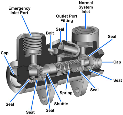
When a shuttle valve is in the normal operation position, fluid has a free flow from the normal system inlet port, through the valve, and out through the outlet port to the actuating unit. The shuttle is seated against the alternate system inlet port and held there by normal system pressure and by the shuttle valve spring. The shuttle remains in this position until the alternate system is activated. This action directs fluid under pressure from the alternate system to the shuttle valve and forces the shuttle from the alternate system inlet port to the normal system inlet port. Fluid from the alternate system then has a free flow to the outlet port, but is prevented from entering the normal system by the shuttle, which seals off the normal system port.
The shuttle may be one of four types: (1) sliding plunger, (2) spring-loaded piston, (3) spring-loaded ball, or (4) spring-loaded poppet. In shuttle valves that are designed with a spring, the shuttle is normally held against the alternate system inlet port by the spring.
Two-Way Valves
The term two-way indicates that the valve contains and controls two functional flow control ports — an inlet and an outlet. A two-way, sliding spool directional control valve is shown in Figure 6-29. As the spool is moved back and forth, it either allows fluid to flow through the valve or prevents flow. In the open position, the fluid enters the inlet port, flows around the shaft of the spool, and through the outlet port. The spool cannot move back and forth by difference of forces set up within the cylinder, since the forces there are equal. As indicated by the arrows against the pistons of the spool, the same pressure acts on equal areas on their inside surfaces. In the closed position, one of the pistons of the spool simply blocks the inlet port, thus preventing flow through the valve.
A number of features common to most sliding spool valves are shown in Figure 6-29. The small ports at either end of the valve housing provide a path for any fluid that leaks past the spool to flow to the reservoir. This prevents pressure from building up against the ends of the pistons, which would hinder the movement of the spool. When spool valves become worn, they may lose balance because of greater leakage on one side of the spool than on the other. In that event, the spool would tend to stick when it is moved back and forth. Small grooves are therefore machined around the sliding surface of the piston; and in hydraulic valves, leaking liquid will encircle the pistons and keep the contacting surfaces lubricated and centered.
Three-Way Valves
Three-way valves contain a pressure port, a cylinder port, and a return or exhaust port. The three-way directional control valve is designed to operate an actuating unit in one direction; it permits either the load on the actuating unit or a spring to return the unit to its original position.
Cam-Operated Three-Way Valves
The operation of a cam-operated, three-way, poppet-type directional control valve is shown in Figure 6-34. View A shows fluid under pressure forcing the piston outward against a load. The upper poppet (2) is unseated by the inside cam (5), permitting fluid to flow from the line (3) into the cylinder to actuate the piston. The lower poppet (1) is seated, sealing off the flow into the return line (4). As the force of the pressurized fluid extends the piston rod, it also compresses the spring in the cylinder.
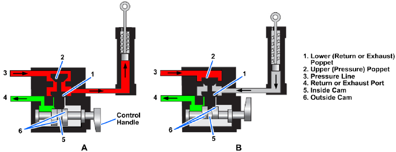
View B shows the valve with the control handle turned to the opposite position. In this position, the upper poppet (2) is seated, blocking the flow of fluid from the pressure line (3). The lower poppet (1) is unseated by the outside cam (6). This releases the pressure in the cylinder and allows the spring to expand, which forces the piston rod to retract. The fluid from the cylinder flows through the control valve and out the return port (4). In hydraulic systems, the return port is connected by a line to the reservoir. In pneumatic systems, the return port is usually open to the atmosphere.
Pilot-Operated Three-Way Valves
A pilot-operated, poppet-type, three-way directional control valve is shown in Figure 6-35. Valves of this design are often used in pneumatic systems. This valve is normally closed and is forced open by fluid pressure entering the pilot chamber. The valve contains two poppets connected to each other by a common stem. The poppets are connected to diaphragms which hold them in a centered position.
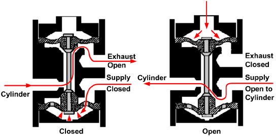
The movement of the poppet is controlled by the pressure in the pilot port and the chamber above the upper diaphragm. When the pilot chamber is not pressurized, the lower poppet is seated against the lower valve seat. Fluid can flow from the supply line through the inlet port and through the holes in the lower diaphragm to fill the bottom chamber. This pressure holds the lower poppet tightly against its seat and blocks flow from the inlet port through the valve. At the same time, due to the common stem, the upper poppet is forced off of its seat. Fluid from the actuating unit flows through the open passage, around the stem, and through the exhaust port to the atmosphere.
When the pilot chamber is pressurized, the force acting against the diaphragm forces the poppet down. The upper poppet closes against its seat, blocking the flow of fluid from the cylinder to the exhaust port. The lower poppet opens, and the passage from the supply inlet port to the cylinder port is open so that the fluid can flow to the actuating unit.
The valve in Figure 6-35 is a normally closed valve. Normally open valves are similar in design. When no pressure is applied to the pilot chamber, the upper poppet is forced off of its seat and the lower poppet is closed. Fluid is free to flow from the inlet port through the cylinder to the actuating unit. When pilot pressure is applied, the poppets are forced downward, closing the upper poppet and opening the lower poppet. Fluid can now flow from the cylinder through the valve and out the exhaust port to the atmosphere.
Four-Way Valves
Most actuating devices require system pressure for operation in either direction. The four-way directional control valve, which contains four ports, is used to control the operation of such devices. The four-way valve is also used in some systems to control the operation of other valves. It is one of the most widely used directional control valves in fluid power systems.
The typical four-way directional control valve has four ports: a pressure port, a return or exhaust port, and two cylinder or working ports. The pressure port is connected to the main system pressure line and the return line is connected to the reservoir in hydraulic systems. In pneumatic systems the return port is usually vented to the atmosphere. The two cylinder ports are connected by lines to the actuating units.
Poppet-Type Four-Way Valves
Figure 6-36 shows a typical four-way, poppet-type directional control valve. This is a manually operated valve and consists of a group of conventional spring-loaded poppets. The poppets are enclosed in a common housing and are interconnected by ducts to direct the flow of fluid in the desired direction.
In some versions of this type of valve, the cam lobes are designed so that the two return/exhaust poppets are open when the valve is in the neutral position. This compensates for thermal expansion, because both working lines are open to the return/exhaust when the valve is in the neutral position.
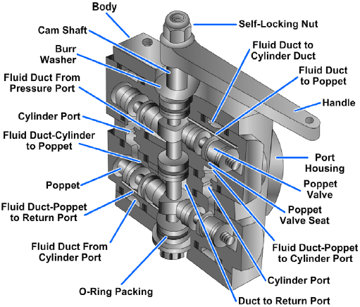
The poppets are actuated by cams on a camshaft (Figure 6-36). The camshaft is controlled by the movement of the handle. The valve may be operated by manually moving the handle, or, in some cases, the handle may be connected by mechanical linkage to a control handle, which is located in a convenient place for the operator some distance from the valve.
The camshaft may be rotated to any one of three positions (neutral and two working positions). In the neutral position the camshaft lobes are not contacting any of the poppets. This assures that the poppet springs will hold all four poppets firmly seated. With all poppets seated, there is no fluid flow through the valve. This also blocks the two cylinder ports, so when the valve is in neutral, the fluid in the actuating unit is trapped. Relief valves are installed in both working lines to prevent overpressurization caused by thermal expansion.
The poppets are arranged so that rotation of the camshaft will open the proper combination of poppets to direct the flow of fluid through the desired working line to an actuating unit. At the same time, fluid will be directed from the actuating unit through the opposite working line, through the valve, and back to the reservoir (hydraulic systems) or exhausted to the atmosphere (pneumatic systems).
To stop rotation of the camshaft at an exact position, a stop pin is secured to the body and extends through a cutout section of the camshaft flange. This stop pin prevents overtravel by ensuring that the camshaft stops rotating at the point where the cam lobes have moved the poppets the greatest distance from their seats and where any further rotation would allow the poppets to start returning to their seats.
O-rings are spaced at intervals along the length of the shaft to prevent external leakage around the ends of the shaft and internal leakage from one of the valve chambers to another. The camshaft has two lobes, or raised portions. The shape of these lobes is such that when the shaft is placed in the neutral position the lobes will not contact any of the poppets.
When the handle is moved in either direction from neutral, the camshaft is rotated. This rotates the lobes, which unseat one pressure poppet and one return/exhaust poppet (Figure 6-37). The valve is now in the working position. Fluid under pressure, entering the pressure port, flows through the vertical fluid passages in both pressure poppets seats. Since only one pressure poppet, IN (2), is unseated by the cam lobe, the fluid flows past the open poppet to the inside of the poppet seat. From there it flows through the diagonal passages, out one cylinder port, C2, and to the actuating unit.
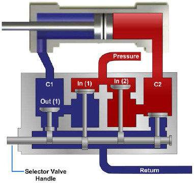
Return fluid from the actuating unit enters the other cylinder port, C1. It then flows through the corresponding fluid passage, past the unseated return poppet, OUT (1), through the vertical fluid passages, and out the return/exhaust port. When the camshaft is rotated in the opposite direction to the neutral position, the two poppets seat and the flow stops. When the camshaft is further rotated in this direction until the stop pins hits, the opposite pressure and return poppets are unseated. This reverses the flow in the working lines, causing the actuating unit to move in the opposite direction.
Rotary Spool Valve
Four-way directional control valves of this type are frequently used as pilot valves to direct flow to and from other valves (Figure 6-38). Fluid is directed from one source of supply through the rotary valve to another directional control valve, where it positions the valve to direct flow from another source to one side of an actuating unit. Fluid from the other end of the main valve flows through a return line, through the rotary valve, to the return or exhaust port.
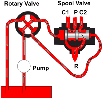
The principal parts of a rotary spool directional control valve are shown in Figure 6-39. Figure 6-39 shows the operation of a rotary spool valve. Views A and C show the valve in a position to deliver fluid to another valve, while view B shows the valve in the neutral position, with all passages through the valve blocked. Rotary spool valves can be operated manually, electrically, or by fluid pressure.
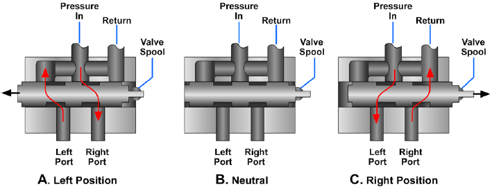
Sliding Spool Valve
The sliding spool four-way directional control valve is similar in operation to the two-way valve previously described in this chapter. It is simple in its principle of operation and is the most durable and trouble-free of all four-way directional control valves.
The valve described in the following paragraphs is a manually operated type. The same principle is used in many remotely controlled directional control valves.
The valve (Figure 6-40) consists of a valve body containing four fluid ports — pressure (P), return/exhaust (R), and two cylinder ports (C1 and C2). A hollow sleeve fits into the main bore of the body. There are O-rings placed at intervals around the outside diameter of the sleeve. These O-rings form a seal between the sleeve and the body, creating chambers around the sleeve. Each of the chambers is lined up with one of the fluid ports in the body. The drilled passage in the body accounts for a fifth chamber, which results in having the two outboard chambers connected to the return/exhaust port. The sleeve has a pattern of holes drilled through it to allow fluid to flow from one port to another. A series of holes are drilled into the hollow center sleeve in each chamber.
The sleeve is prevented from turning by a sleeve retainer bolt or pin that secures it to the valve body.
The sliding spool fits into the hollow center sleeve. This spool is similar to the spool in the two-way valve, except that this spool has three pistons or lands. These lands are lapped or machine fitted to the inside of the sleeve.
One end of the sliding spool is connected to a handle either directly or by mechanical linkage to a more desirable location. When the control handle is moved, it will position the spool within the sleeve. The lands of the spool then line up different combinations of fluid ports, thus directing a flow of fluid through the valve.
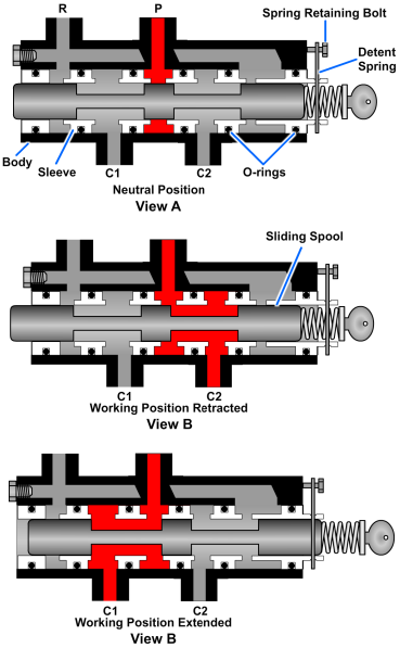
The detent spring is a clothespin-type spring, secured to the end of the body by a spring retaining bolt. The two legs of the spring extend down through slots in the sleeve and fit into the detents. The spool is gripped between the two legs of the spring. To move the spool, enough force must be applied to spread the two spring legs and allow them to snap back into the next detent, which would be for another position.
Figure 6-40, view A, shows a manually operated sliding spool valve in the neutral position. The detent spring is in the center detent of the sliding spool. The center land is lined up with the pressure port (P) preventing fluid from flowing into the valve through this port. The return/exhaust port is also blocked, preventing flow through that port. With both the pressure and return ports blocked, fluid in the actuating lines is trapped. For this reason, a relief valve is usually installed in each actuating line when this type of valve is used.
Figure 6-40, view B, shows the valve in the working position with the end of the sliding spool retracted. The detent spring is in the outboard detent, locking the sliding spool in this position. The lands have shifted inside the sleeve, and the ports are opened. Fluid under pressure enters the sleeve, passes through it by way of the drilled holes, and leaves through cylinder port C2. Return fluid, flowing from the actuator enters port C1, flows through the sleeve, and is directed out the return port back to the reservoir or exhausted to the atmosphere. Fluid cannot flow past the spool lands because of the lapped surfaces.
Figure 6-40, view C, shows the valve in the opposite working position with the sliding spool extended. The detent spring is in the inboard detent. The center land of the sliding spool is now on the other side of the pressure port, and the fluid under pressure is directed through the sleeve and out port C1. Return fluid flowing in the other cylinder port is directed to the drilled passage in the body. It flows along this passage to the other end of the sleeve where it is directed out of the return/exhaust port.
The directional control valves previously discussed are for use in closed-center fluid power systems. Figure 6-41 shows the operation of a representative open-center, sliding spool directional control valve.
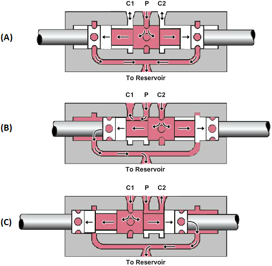
When this type of valve is in the neutral position, (Figure 6-41, view A) fluid flows into the valve through the pressure port (P) through the hollow spool, and return to the reservoir.
When the spool is moved to the right of the neutral position, (Figure 6-41, view B) one working line (C1) is aligned to system pressure and the other working line (C2) is open through the hollow spool to the return port. Figure 6-41, view C shows the flow of fluid through the valve with the spool moved to the left of neutral.
PDH Classroom offers a continuing education course based on this hydraulic valves reference page. This course can be used to fulfill PDH credit requirements for maintaining your PE license.
Now that you've read this reference page, earn credit for it!
