Chapter 7: Sealing Devices and Materials
This page provides the chapter on hydraulic sealing devices and materials from the U.S. Navy's fluid power training course, NAVEDTRA 14105A, "Fluid Power," Naval Education and Training Professional Development and Technology Center, July 2015.
Other related chapters from the Navy's fluid power training course can be seen to the right.
Sealing Devices and Materials
Sealing devices and materials prevent leakage, and contain pressure or exclude contamination between components. The two most common classifications of seals are gaskets and packings. There are many commercial types and forms of packing and gasket materials. The Navy has simplified the selection of packing and gasket materials commonly used in service.
This chapter deals primarily with the different types of materials used in the construction of seals. You will also learn about the different shapes and designs of seals and their application as gaskets and/or packings in fluid power systems. Lastly in this chapter are sections concerning the functions of wipers and scrapers in fluid power systems and the selection, storage, and handling of sealing devices.
Learning Objectives
When you have completed this chapter, you will be able to do the following:
- Recognize the required characteristics of sealing devices used in fluid power systems.
- Identify the functions of sealing devices used in fluid power systems.
- Recognize the types and materials of sealing devices used in fluid power systems.
- Recognize the identification procedures of various types of seals.
- Describe the characteristics of various types of seals.
- Describe the inspection of various types of seals.
- Explain the installation techniques of various types of seals.
Definitions
Gaskets and Packings
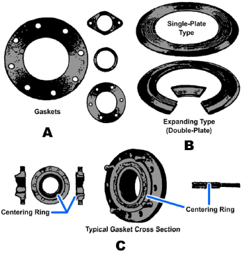
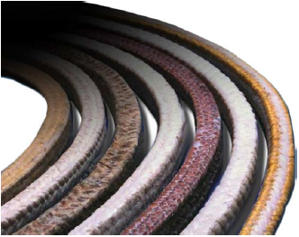
Gaskets (Figure 7-1) depend upon mechanical compression to provide a positive seal between two stationary joints, whereas packings generally are used where some form of relative motion occurs between members of the joint. Packing (Figure 7-2) consists of deformable material, which is shaped by adjustable compression to provide a controlled seal. Certain types of seals (for example, the O-ring, which is discussed later) may be used either as a gasket or a packing.
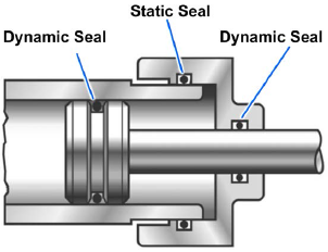
The sealing devices and materials used in fluid power systems and components are divided into two general classes — static seals and dynamic seals (Figure 7-3).
Static and Dynamic Seals
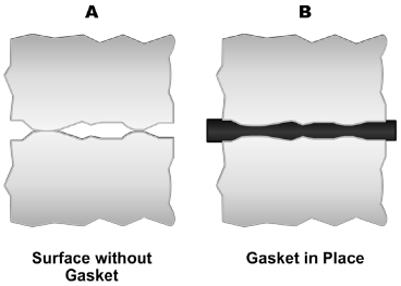
The static seal is used to prevent leakage in a mechanical joint where there is no relative motion between mating surfaces. Material used to create a seal between two stationary faces of a mechanical joint are called gaskets. The gasket must function to confine liquids or gasses within an assembly and maintain this seal under various operating conditions. To create an effective barrier, gasket material will deform to fill the space between imperfect mating surfaces of mechanical joints to prevent fluids from leaking. This compression requires that the joint be tightly bolted or otherwise held together. The compression of a gasket forming a seal between mating parts is shown in Figure 7-4.
The dynamic seal (Figure 7-3) is a seal provided in a mechanical coupling where movement between the sealed surfaces is intended, such as packing material sealing to a rotating or reciprocating shaft. Material used to provide a seal in a mechanical coupling where some form of movement between the surfaces to be sealed is intended or anticipated is called Packing. Packing material usually consists of bulk deformable materials which are shaped by manually adjusted compression.
Rotating, Reciprocating, and Oscillating Seals
Rotary seals are used in a variety of different application conditions. These conditions can vary from high-speed shaft rotation with light oil mist, to a low speed reciprocating shaft in muddy environments. Reciprocating seals involve relative reciprocating motion along the shaft axis between the inner and outer elements. In reciprocating seal applications, the O-ring slides or rocks back and forth within its gland with the reciprocating motion. Oscillating seals are commonly used in faucet valves. In oscillating applications, the shaft or housing rotates back and forth through a limited number of turns around the axis of the shaft.
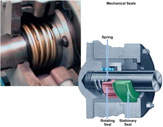
Mechanical seals are sealing devices that are installed on rotating equipment such as pumps to prevent the leakage of liquids and gases from escaping the operating system. A mechanical seal consists of two principle components. One component is stationary and the other rotates against it to achieve a seal (Figure 7-5). There are many types of mechanical seal, ranging from simple single spring designs to considerably more complex cartridge seal types. The design, arrangement, and materials of construction are essentially determined by the pressure, temperature, speed of rotation, and product being sealed.
Seal Materials
Many different materials have been used in the development of sealing devices. The material used for a particular application depends on several factors: fluid compatibility, resistance to heat, pressure, wear resistance, hardness, and type of motion.
The selection of the correct packings and gaskets and their proper installation are important factors in maintaining an efficient fluid power system. The types of seals to be used in a particular piece of equipment are specified by the equipment manufacturer.
Often the selection of seals is limited to seals covered by military specifications. However, there are occasions when nonstandard or proprietary seals reflecting the advancing state of the art may be approved. Thus, it is important to follow the manufacturer's instructions when you replace seals. If the proper seal is not available, you should give careful consideration in the selection of a suitable substitute. To find the right packing material, check the maintenance requirement card (MRC) or the Commander Naval Sea Systems Command (NAVSEA) packing and gasket chart. The MRC lists the symbol numbers and the size and number or rings required. The NAVSEA packing and gasket chart lists symbol numbers and materials. For additional information concerning packing and gasket material, refer to Naval Ships' Technical Manual (NSTM), Chapter 078.
Seals are made of materials that have been carefully chosen or developed for specific applications. These materials include tetrafluoroethylene (TFE), commonly called Teflon; synthetic rubber (elastomers); cork; leather; metal; and asbestos (its use is not permitted in the construction, overhaul, repair or maintenance of Navy ships where suitable substitute materials have been identified). Non-asbestos materials have been identified for use in some gasket applications and must be used in place of asbestos gaskets in such applications when available. Some of the most common materials used to make seals for fluid power systems are discussed in the following paragraphs.
Cork
Cork has several of the required properties, which makes it ideally suited as a sealing material in certain applications. The compressibility of cork seals makes them well suited for confined applications in which little or no spread of the material is allowed. The compressibility of cork also makes a good seal that can be cut to any desired thickness and shape to fit any surface and still provide an excellent seal.
One of the undesirable characteristics of cork is its tendency to crumble. If cork is used as packing or in areas where there is a high fluid pressure and/or high flow velocity, small particles will be cast off into the system. Cork use in fluid power systems is therefore limited. It is sometimes used as gasket materials for inspection plates of hydraulic reservoirs.
Cork should not be used where temperatures exceed 160 degrees Fahrenheit (°F) (71 Celsius (°C)) or at sub-zero temperatures.
Cork and Rubber
Cork and rubber seals are made by combining synthetic rubber and cork. This combination has the properties of both materials. This means that seals can be made with the compressibility of cork, but with a resistance to fluid comparable to the synthetic rubber on which they are based. Cork and rubber composition is sometimes used to make gaskets for applications similar to those described for cork gaskets.
Leather
Leather is a closely knit material that is generally tough, pliable, and relatively resistant to abrasion, wear, stress, and the effects of temperature changes. Because it is porous, it is able to absorb lubricating fluids. This porosity makes it necessary to impregnate leather for most uses. In general, leather must be tanned and treated to make it useful as a gasket material. The tanning processes are those normally used in the leather industry.
Leather is generally resistant to abrasion regardless of whether the grain side or the flesh side is exposed to abrasive action. Leather remains flexible at low temperatures and can be forced with comparative ease into contact with metal flanges. When properly impregnated, it is impermeable to most liquids and some gases, and is capable of withstanding the effects of temperatures ranging from −70 °F to +220 °F.
Leather has four basic limitations. First, the size of the typical hide limits the size of the seals that can be made from leather. A second limitation is the number of seals that are acceptable. Another limitation is that under heavy mechanical pressures leather tends to extrude. Finally, many of the properties (such as impermeability, tensile strength, high- and low-temperature resistance, pliability, and compatibility with environment) depend upon the type of leather and impregnation. Leathers not tanned and impregnated for specific conditions and properties will become brittle, dry, and completely degreased by exposure to particular chemicals. Leather is never used with steam pressure of any type, or with acid or alkali solutions.
Leather may be used as packing. When molded into V's and U's, cups, and other shapes, it can be applied as dynamic packing, while in its flat form it can be used as straight compression packing.
Metal
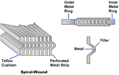
Various types of metals are used in gasket products. Sheet lead and copper are effective, since they are soft metals and easily compressed. Woven-metal and spun-metal products are being used in high temperature service applications. A combination of metal and other gasket materials are commonly used where high strength, service pressure and working temperature demands are great. Spiral-wound gaskets (Figure 7-6) are preformed for a particular assembly and are available in many sizes. The gasket is normally steel formed with another softer material (fibrous glass, graphite, etc). The gasket consists of multiple layers of material spirally wound and cut to a required thickness.
Rubber
The term rubber covers many natural and synthetic rubbers, each of which can be compounded into numerous varieties. The characteristics of these varieties have a wide range, as shown in Table 7-1. The table shows, with the exception of a few basic similarities, that rubbers have diverse properties and limitations; therefore, specific applications require careful study before the sealing material is selected.
Natural rubbers have many of the characteristics required in an effective seal. However, their very poor resistance to petroleum fluids and rapid aging when exposed to oxygen or ozone limit their use. Rubber gaskets are usually restricted to low pressure uses.
There are two general classes of synthetic rubber seals. One class is made entirely of a certain synthetic rubber. The term frequently used to describe this class of seal is homogeneous (having uniform structure or composition throughout). The other class of seal is made by impregnating woven cotton duck or fine-weave asbestos with synthetic rubber (see NSTM, Chapter 078 for asbestos substitutes), this class is sometimes referred to as fabricated seals.
For additional information concerning sealing materials, refer to NSTM, Chapter 078.
| Natural Rubber a | Styrene Butadiene Rubber (SBR) | Acrylonitrile Butadiene Rubber (Nitrile b ) | Polychloroprene (Neoprene c ) | Butyl e | Polysulfide (Thiokol f ) | Silicone g | Polyacrylates (Acrylic) | ||
|---|---|---|---|---|---|---|---|---|---|
| Low Swell | High Swell | ||||||||
| Specific Gravity: Pure Gum | 0.92 | 0.94 | 0.98 | 0.98 | 1.23 | 0.92 | 1.34 | 0.98 | 1.1 |
Tensile Strength (psi), Pure Gum
|
3000 4500 |
400 3000 |
600 3000 |
600 3500 |
3500 3500 |
3000 3000 |
300 1500 |
200 450 |
--- 2500 |
| Elongation, percent | 700 | 500 | 600 | 600 | 600 | 700 | 400 | 300 | 500 |
| Tear Resistance | G | P-F | F | F | G | G | P-F | P | F |
Aging Resistance to:
|
F P-G F-G G |
P P-G F-G G |
P P-G G G |
P P-G G G |
E G-E VG VG |
E G-E G E |
E G-E P G |
E E E E |
VG VG E VG |
| Compression Set Resistance | G | G | VG | VG | d | P-G | P | E | P-G |
Oil-Resistance:
|
P P |
P P |
E G |
G E |
F G |
P P |
E E |
P G |
E E |
Gasoline Resistance:
|
P P |
P P |
P F |
G E |
P G |
P P |
E E |
P P |
E E |
Acid Resistance:
|
G F-G |
G F-G |
G G |
G G |
G F |
E E |
F F |
F P |
F F |
Alkali Resistance:
|
G F |
G F |
G F |
G F |
G G |
G G |
P P |
F P |
P P |
| High-Temperature Resistance [200°F (93°C) or more] | F | G | G | G | G | G | F-G | E | E |
| Low-Temperature Resistance [−67°F (−55°C) or more] | G | G | F | F | F | G | F | E | P |
| Impermeability to Gases | F | F | F | F | G | E | G | G | G |
| Water Resistance | G | VG | VG | VG | F | G | F | F | F |
| NOTE: E = Excellent, VG = Very Good, G = Good, F = Fair, P = Poor | |||||||||
| a Swells in contact with turpentine, carbon bisulfide, chloroform, carbon tetrachloride, and vegetable oils. White glycerine, ethylene glycol, and water produce negligible swell. Functions best at temperature under 160 degrees F, but can tolerate intermittent exposures to 250 degrees F. | |||||||||
| b Resist swelling action of petroleum oils, fuels, and solvents. Usually will not adhere to metal flanges. | |||||||||
| c Includes types GN and W. | |||||||||
| e Excellent resistance to vegetable oils, dilute organic acids, and alkalis. Poor solvent resistance. Pool compression set properties. | |||||||||
| f Includes types PR-1 and ST. Excellent solvent resistance. | |||||||||
| g Excellent dielectric properties, high- and low-temperature resistance, and resistance to tendencies to adhere at high temperatures. Good resistance to oxidation, weathering, high-aniline-point oils. Poor resistance to low-aniline-point oils, aromatic and non-aromatic gasolines. Low abrasion resistance. Deteriorates in contact with steam under pressure. | |||||||||
Types of Seals
Fluid power seals are usually typed according to their shape or design. These types include T-seals, V-rings, O-rings, U-cups, and so on. Some of the most commonly used seals are discussed in the remainder of this chapter.
T-Seals
The T-seal has an elastomeric bidirectional sealing element resembling an inverted letter T. This sealing element is always paired with two special extrusion-resisting backup rings, one on each side of the T. The basic T-seal configuration is shown in Figure 7-7, view A. The backup rings are single turn, bias cut, and usually made of TFE (Tetrafluoroethylene), molybdenum-disulfide-impregnated nylon, or a combination of TFE and nylon. Nylon is widely used for T-seal backup rings because it provides excellent resistance to extrusion and has low friction characteristics.
The special T-ring configuration adds stability to the seal, eliminating spiraling and rolling. T-seals are used in applications where large clearances could occur as a result of the expansion of the thin-walled hydraulic cylinder. The T-ring is installed under radial compression and provides a positive seal at zero or low pressure. Backup rings, one on each side, ride free of T-ring flanges and the rod or cylinder wall (Figure 7-7, view B). These clearances keep seal friction to a minimum at low pressure. When pressure is applied (Figure 7-7, view C), the T-ring acts to provide positive sealing action as fluid pressure increases. One frequently used T-ring, manufactured by Greene, Tweed and Company (called a G-T Ring) incorporates a unique, patented backup ring feature. One corner on the inside diameter (ID) of each radius-styled backup ring on the G-T Ring set has been rounded to mate with the inside corner of the rubber T. Figure 7-7, views B and C, shows the G-T Ring.

There is no military standard part numbering system by which T-seals can be identified. In general, each manufacturer issues proprietary part numbers to identify seals. However, it is common practice to identify T-seal sizes by the same dash numbers used for equivalent O-ring sizes (discussed later in this chapter) as defined by AS568 and MS28775 dimension standards. Typically, an O-ring groove that accepts a certain O-ring dash number will accept the same dash number T-seal.
In the absence of an existing military standard for identifying T-seals, a new and simple numbering system was created to identify T-seals required for hydraulic actuators (piston seals only) without reference to a particular manufacturer's part number. The Navy number is composed of the letters G-T followed by a dash number of three digits and one letter, R, S, or T (for example, G-T-217T). The three digits are the appropriate O-ring size dash number according to AS568 or MS28775. The letters R, S, and T designate the number of backup rings that the groove of the T-seal is designed to accommodate: none, one, or two, respectively.
V-Rings
The V-ring is one of the most frequently used dynamic seals in ship service although its identification, installation, and performance are probably most misunderstood. Properly selected and installed, V-rings can provide excellent service life; otherwise, problems associated with friction, rod and seal wear, noise, and leakage can be expected.
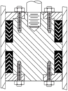
The V-ring is the part of the packing set that does the sealing. It has a cross section resembling the letter V (Figure 7-8), from which its name is derived. To achieve a seal, the V-ring must be installed as part of a packing set or stack, which includes one male adapter, one female adapter, and several V-rings (Figure 7-8). The male adapter is the first ring on the pressure end of the packing stack and is flat on one side and wedge-shaped on the other to contain the V of the adjacent V-ring. The female adapter, the last ring of the packing stack, is flat on one side and V-shaped on the other to properly support the adjacent V-ring. Proper design and installation of the female adapter has significant impact on the service life and performance of the V-rings because the female adapter bridges the clearance gap between the moving surfaces and resists extrusion.
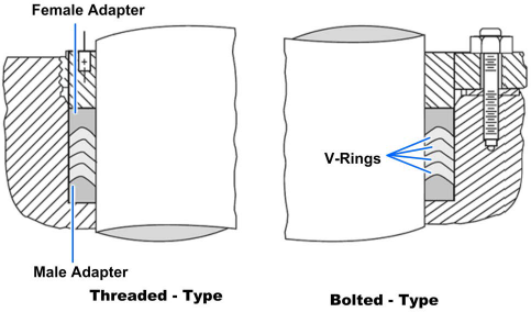
The packing set is installed in a cavity that is slightly deeper than the free stack height (the nominal overall height of a V-ring packing set, including the male and female adapters as measured before installation) and as wide as the nominal cross section of the V-rings. This cavity, called a packing gland or stuffing box, contains and supports the packing around the shaft, rod, or piston. Adjustment of the packing gland depth through the use of shims or spacers is usually necessary to obtain the correct squeeze or clearance on the packing stack for good service life.
Two basic installations apply to V-ring packings. The more common is referred to as an outside packed installation, in which the packing seals against a shaft or rod, as shown in Figure 7-8. The inside packed installation is shown as a piston seal in Figure 7-9. When V-ring packing is to be used in an inside packed installation, only endless ring packing should be used. Pressures exist in both directions, as on a double-acting piston, opposing sets of packing should always be installed so the sealing lips face away from each other (Figure 7-9). This prevents trapping pressure between the sets of packings. The female adapters in inside packed installations should always be located adjacent to a fixed or rigid part of the piston.
O-Rings
An O-ring is circular in shape, and its cross section is small in relation to its diameter. O-rings are usually molded from rubber compounds; however, they can be molded or machined from plastic materials. The O-ring is usually fitted into a rectangular groove (usually called a gland) machined into the mechanism to be sealed. An O-ring seal consists of an O-ring mounted in the gland so that the O-ring's cross section is compressed (squeezed) when the gland is assembled (Figure 7-10).

An O-ring sealing system is often one of the first sealing systems considered when a fluid closure is designed because of the following advantages of such a system:
- Simplicity
- Ruggedness
- Low cost
- Ease of installation
- Ease of maintenance
- No adjustment required
- No critical torque in clamping
- Low distortion of structure
- Small space requirement
- Reliability
- Effectiveness over wide pressure and temperature ranges
As stated previously, O-rings are used in both static (as gaskets) and dynamic (as packing) applications. An O-ring will almost always be the most satisfactory choice of seal in static applications if the fluids, temperatures, pressure, and geometry permit.
Standard O-ring packings are not specifically designed to be used as rotary seals. When infrequent rotary motion or low peripheral velocity is involved, standard O-ring packings may be used, provided consistent surface finishes over the entire gland are used and eccentricities are accurately controlled. O-rings cannot compensate for out-of-round or eccentrically rotating shafts.
As rotary seals, O-rings perform satisfactorily in two application areas:
- In low-speed applications where the surface speed of the shaft does not exceed 200 feet per minute (ft/min)
- In high-speed moderate-pressure applications, between 50 and 800 pounds per square inch (psi)
The use of low-friction extrusion-resistant devices helps prolong the life and improve the performance of O-rings used as rotary seals.
O-rings are often used as reciprocating seals in hydraulic and pneumatic systems. While best suited for short-stroke, relatively small diameter applications, O-rings have been used successfully in long-stroke, large diameter applications. Glands for O-rings used as reciprocating seals are usually designed according to MIL-G-5514 to provide a squeeze that varies from 8 to 10 percent minimum and 13.5 to 16 percent maximum. A squeeze of 20 percent is allowed on O-rings with a cross section of 0.070 inch or less. In some reciprocating pneumatic applications, a floating O-ring design may simultaneously reduce friction and wear by maintaining no squeeze by the gland on the O-ring. When air pressure enters the cylinder, the air pressure flattens the O-ring, causing sufficient squeeze to seal during the stroke. If the return stroke does not use pneumatic power, the O-ring returns to its round cross section, minimizing drag and wear on the return stroke.
Identification
As a maintenance person or supervisor working with fluid power systems, you must be able to positively identify, inspect, and install the correct size and type of O-ring to ensure the best possible service. These tasks can be difficult since part numbers cannot be put directly on the seals and because new types of seals are continually introduced and others made obsolete. (NSTM, chapter 078, contains a table that cross-references obsolete and current O-ring specifications for ship applications.)
O-rings are packaged in individually sealed envelopes. O-ring seals manufactured to government specifications are marked according to the requirements of the specification and standard. The required marking for each package is as follows:
- National stock number (NSN)
- Nomenclature
- Military part number
- Material specification
- Manufacturer's name
- Manufacturer's compound number
- Manufacturer's batch number
- Contract number
- Cure date
Keep preformed packings in their original envelopes, which provide preservation, protection, identification, and cure date.
When you select an O-ring for installation, carefully observe the information on the package. If you cannot positively identify an O-ring, discard it. The part number on the sealed package provides the most reliable and complete identification.
Sizes
A standardized dash number system for O-ring sizes is contained in Aerospace Standard AS568 published by the Society of Automotive Engineers. The dash numbers are divided into groups of one hundred. Each hundred group identifies the cross section size of the O-rings within the group (Table 7-2).
| Dash Number | Cross Section [Inches] |
|---|---|
| -001 thru -099 | 0.070 and smaller |
| -100 thru -199 | 0.103 |
| -200 thru -299 | 0.139 |
| -300 thru -399 | 0.210 |
| -400 thru -499 | 0.275 |
The 900 series dash numbers contained in AS568 identify all the presently standardized straight thread tube fitting boss gaskets. With the exception of -901, the last two digits of the dash designate the tube size in 16ths of an inch. For example, the -904 size is for a 1/4-inch tube.
Dimensions
The critical dimensions of an O-ring are its ID, its cross-sectional diameter (W), and the height and width of the residual molding flash (Figure 7-11).
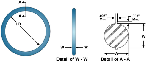
Nominal dimensions have been used to describe O-ring sizes, although this practice is rapidly being replaced by the use of dash numbers. The actual ID of a seal will be slightly less than the nominal ID, but the actual outside diameter (OD) will be slightly larger than the nominal OD. For example, an AS568-429 O-ring is described in nominal dimensions as 5 inches ID by 5 1/2 inches OD by 1/4 inch W. Actual dimensions are 4.975 inches ID by 5.525 inches OD by 0.275 inches W.
Specifications
Material and performance requirements for O-rings are often identified in military specifications. The dimensions of these O-rings will usually be found in accompanying slash sheets (which bear the specification number and are a part of the specification) or will be identified by various drawings and standards that relate to the specification. Included among the specifications are Air Force-Navy Standards (AN), Military Standards (MS), and National Aerospace Standards (NAS). If the specification does not identify sizes, the sizes should be identified by the AS568 dash number. Usually, you can use drawings, technical manuals, and allowance parts lists (APLs) to identify replacement O-rings.
Cure Date
The cure date is the date the rubber is fully cured or the manufacture date. Two methods of expressing the cure date are as follows:
- Shelf life to a maximum of 3 years. Cure date stated in terms of month of calendar year and the year, e.g., 6-13
- Shelf life in excess of 3 years. Cure date stated in terms of the quarter of calendar year and the year, e.g., 2Q-13
For additional information concerning sealing materials, refer to NSTM, Chapter 078.
Shelf Life and Expiration Date
The shelf life for rubber products is the period of time during which an unopened, properly stored item should be suitable for unrestricted use.
Check the age of natural or synthetic rubber preformed packings before installation to determine whether they are acceptable for use. Make a positive identification, indicating the source, cure date, and expiration date. Ensure that this information is available for all packing used. Shelf life requirements do not apply once the packing is installed in a component. If the source of an item cannot be determined, or it is not in the original package, discard it.
The expiration date is the date after which packing should not be installed. The expiration date of all packings can be determined by adding the shelf life to the cure date.
Replacement
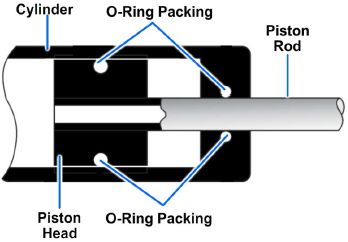
A typical O-ring installation is shown in Figure 7-12. When such an installation shows signs of internal or external leakage, the component must be disassembled and the seals replaced. Sometimes components must be resealed because of the age limitations of the seals. The O-ring should also be replaced whenever a gland that has been in service is disassembled and reassembled.
Often a poor O-ring installation begins when an old seal is removed. O-ring removal involves working with parts that have critical surface finishes. If hardened-steel, pointed, or sharp-edged tools are used for removal of O-rings or backup rings, scratches, abrasions, dents, and other deformities on critical sealing surfaces can result in seal failure, which, in turn, can result in functional failure of the equipment.
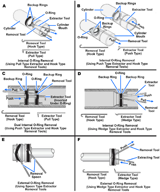
When removing or installing O-rings, do NOT use pointed or sharp-edged tools, which might scratch or mar component surfaces or damage the O-ring. An O-ring tool kit is available in the supply system for O-ring installation or removal. If these tools are not on hand, special tools can be made for this purpose. A few examples of tools used in the removal and installation of O-rings are illustrated in Figure 7-13. These tools should be fabricated from soft metal such as brass or aluminum; however, tools made from phenolic rod, wood, or plastic may also be used.
Tool surfaces must be well rounded, polished, and free of burrs. Check the tools often, especially the surfaces that come in contact with O-ring grooves and critical polished surfaces.
Notice in Figure 7-13, view A, how the hook-type removal tool is positioned under the O-ring and then lifted to allow the extractor tool, as well as the removal tool, to pull the O-ring from its cavity. Figure 7- 13, view B shows the use of another type of extractor tool in the removal of internally installed O-rings.
In Figure 7-13, view C, the extractor tool is positioned under both O-rings at the same time. This method of manipulating the tool positions both O-rings, which allows the hook-type removal tool to extract both O-rings with minimum effort. Figure 7-13, view D, shows practically the same removal as Figure 7-13, view C, except for the use of a different type of extractor tool.
The removal of external O-rings is less difficult than the removal of internally installed O-rings. Figure 7-13, views E and F, show the use of a spoon-type extractor, which is positioned under the seal. After the O-ring is dislodged from its cavity, the spoon is held stationary while the piston is simultaneously rotated and withdrawn. View F is similar to view E, except that only one O-ring is installed, and a different type of extractor tool is used. The wedge-type extractor tool is inserted beneath the O-ring; the hook-type removal tool hooks the O-ring. A slight pull on the latter tool removes the O-ring from its cavity.
After removing all O-rings, you must clean the affected parts that will receive new O-rings. Ensure that the area used for such installations is clean and free from all contamination.
Remove each O-ring that is to be installed from its sealed package and inspect it for defects such as blemishes, abrasions, cuts, or punctures. Although an O-ring may appear perfect at first glance, slight surface flaws may exist. These are often capable of preventing satisfactory O-ring performance. O-rings should be rejected for flaws that will affect their performance.
By rolling the ring on an inspection cone or dowel, you can check the inner diameter surface for small cracks, particles of foreign material, and other irregularities that will cause leakage or shorten its life. The slight stretching of the ring when it is rolled inside out will help to reveal some defects not otherwise visible. You should further check each O-ring by stretching it between the fingers, but take care not to exceed the elastic limits of the rubber. Following these inspection practices will prove to be a maintenance economy. It is far more desirable to take care identifying and inspecting O-rings than to repeatedly overhaul components with faulty seals.
After inspection and prior to installation, lubricate the O-ring and all the surfaces that it must slide over with a light coat of the system fluid or a lubricant approved for use in the system. Consult the applicable technical instruction or NSTM for the correct lubricant for pneumatic systems.
Assembly must be made with care so that the O-ring is properly placed in the groove and not damaged as the gland is closed. During some installations, such as on a piston, it will be necessary to stretch the O-ring. Stretch the O-ring as little and as uniformly as possible. Avoid rolling or twisting the O-ring when maneuvering it into place. Keep the position of the O-ring mold line constant. O-rings should not be left in a twisted condition after installation.
If the O-ring installation requires spanning or inserting through sharp-threaded areas, ridges, slots, and edges, use protective measures, such as the O-ring entering sleeve (Figure 7-14, view A). If the recommended O-ring entering sleeve (a soft, thin-wall, metallic sleeve) is not available, paper sleeves and covers may be fabricated by using the seal package (glossy side out) or lint-free bond paper (Figure 7-14, views B and C).
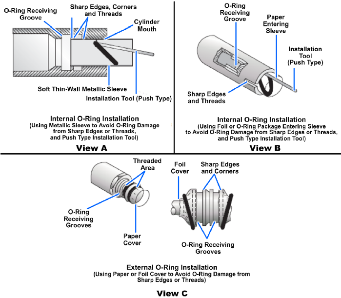
After you place the O-ring in the cavity provided, gently roll the O-ring with your fingers to remove any twist that might have occurred during the installation. After installation, an O-ring should seat snugly but freely in its groove. If backup rings are installed in the groove, be certain the backup rings are installed on the correct side of the ring.
Backup Rings
Backup rings, also referred to as retainer rings, anti-extrusion devices, and non-extrusion rings, are washer-like devices that are installed on the low-pressure side of packing to prevent extrusion of the packing material. Backup rings in dynamic seals minimize erosion of the packing materials and subsequent failure of the seal. At lower pressures, backup rings will prolong the normal wear life of the packing. At higher pressures, backup rings permit greater clearances between the moving parts.
Backup rings can be made of polytetrafluoroethylene, hard rubber, leather, and other materials. The most common material currently used is TFE. Backup rings are available as single-turn continuous (uncut or solid), single-turn (bias) cut, and spiral cut (Figure 7-15). Leather rings are always furnished in solid ring form (unsplit). Rings of TFE are available in all three types.

Packaging and Storing
Backup rings are not color-coded or otherwise marked and must be identified from the packaging labels. The dash number following the military standard number found on the package indicates the size and usually relates directly to the dash number of the O-rings for which the backup ring is dimensionally suited. Backup rings made of TFE do not deteriorate with age and do not have shelf life limitations. TFE backup rings are provided by the manufacturer either in individually sealed packages or on mandrels. If unpackaged rings are stored for a long time without the use of mandrels, a condition of overlap may develop. Overlap occurs when the ID of the backup ring becomes smaller and its ends overlap each other. To correct this overlap condition, stack TFE rings on a mandrel of the correct diameter, and clamp the rings with their coils flat and parallel. Place the rings in an oven at a maximum temperature of 177 °C (350 °F) for approximately 10 minutes. Do not overheat them because fumes from decomposing TFE are toxic. Remove and water-quench the rings. The rings should then be stored at room temperature for 48 hours prior to use.
Installation
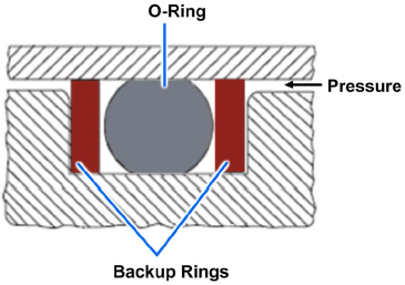
Care must be taken in handling and installing backup rings. Do not insert them with sharp tools. Prior to use, backup rings must be inspected for evidence of compression damage, scratches, cuts, nicks, or frayed conditions. Where backup rings and O-rings are installed in the same groove, never replace the O-ring without replacing the backup rings, or vice versa. Many seals use two backup rings, one on either side of the O-ring (Figure 7-16). Two backup rings are used primarily in situations (such as a reciprocating piston seal) where alternating pressure direction can cause packing to be extruded on both sides of the gland.
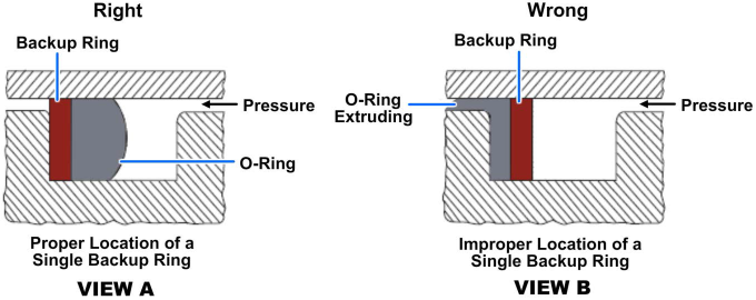
If only one backup ring is used, place the backup ring on the low-pressure side of the packing (Figure 7-17, view A). When a backup ring is placed on the high-pressure side of the packing, the pressure against the relatively hard surface of the backup ring forces the softer packing against the low-pressure side of the gland, resulting in a rapid failure due to extrusion (Figure 7-17, view B).
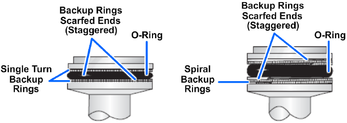
When dual backup rings are installed, stagger the split scarfed ends as shown in Figure 7-18. When installing a spiral cut backup ring (MS28782 or MS28783), be sure to wind the ring correctly to ease installation and ensure optimum performance.
When TFE spiral rings are being installed in internal grooves, the ring must have a right-hand spiral. Figure 7-19, view A, shows how to change the direction of the spiral. The ring is then stretched slightly, as shown in view B, prior to installation into the groove. While the TFE ring is being inserted into the groove, rotate the component in a clockwise direction. This action will tend to expand the ring diameter and reduce the possibility of damaging the ring.
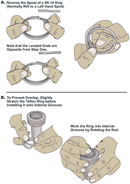
When TFE spiral rings are being installed in external grooves, the ring should have a left-hand spiral. As the ring is being inserted into the groove, rotate the component in a clockwise direction. This action will tend to contract the ring diameter and reduce the possibility of damaging the ring.
In applications where a leather backup ring is called for, place the smooth-grained side of the leather next to the ring. Do not cut leather backup rings. Use a leather backup ring as one continuous ring and lubricate the ring prior to installing it, particularly the smaller sizes. If stretching is necessary for proper installation, soak the backup ring in the system fluid or in an acceptable lubricant at room temperature for at least 30 minutes.
Quad-Rings
The Quad-Ring seal is a special configuration ring packing, manufactured by the Minnesota Rubber and Plastics. As opposed to an O-ring, a Quad-Ring seal has a more square cross-sectional shape with rounded corners (Figure 7-20). The Quad-Ring seal design offers more stability than the O-ring design and practically eliminates the spiraling or twisting that is sometimes encountered with the O-ring.
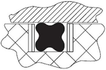
Quad-Ring seals are completely interchangeable with O-rings in the sizes offered by the manufacturer. They may be installed with one or two backup rings, depending upon the specific seal groove application and width. The Quad-Ring seal works well in both hydraulic and pneumatic systems.
Many Quad-Ring seal sizes have been assigned NSNs and are stocked in the Federal Supply System. Quad-Ring seals in manufacturer's sizes designated as Q1 through Q88 are interchangeable with O-rings conforming to AN6227 in the respective dash sizes from -1 through -88. Likewise, Quad-Ring seals in commercial sizes Q101 through Q152 are interchangeable with O-rings conforming to AN6230 in the respective dash sizes from -1 through -52. Therefore, the Quad-Ring seal stock part number uses the AN standard O-ring designations AN6227 and AN6230 and the commercial Q dash number designation. For example, NSNs are found under such reference part numbers as AN6227Q10 and AN6230Q103. If the letter Q does not follow AN6227 or AN6230, the part number is an O-ring not a Quad-Ring seal.
If Quad-Ring seals are not available for maintenance actions, appropriate sized O-rings can be installed and they work satisfactorily.
Quad-O-Dyn Seals
The Quad-O-Dyn, also manufactured by Minnesota Rubber and Plastics, is a special form of the Quad-Ring. The Quad-O-Dyn differs from the Quad-Ring in configuration (Figure 7-21), is harder, is subject to greater squeeze, and is made of a different material. The Quad-O-Dyn seal also works well in O-ring glands.
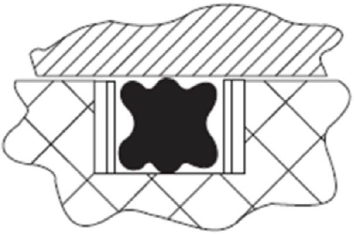
The Quad-O-Dyn is used in relatively few applications. However, for difficult dynamic sealing applications, the Quad-O-Dyn can perform better than the Quad-Ring. Quad-O-Dyn rings are installed in submarine hydraulic systems plant accumulators.
U-Cups and U-Packings
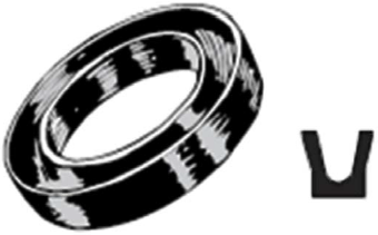
The distinction between U-cups and U-packings results from the difference in materials used in their fabrication. The U-cup is usually made of homogeneous synthetic rubber; U-packings are usually made of leather or fabric-reinforced rubber. Special aspects of each type will be discussed separately. However, all U-cups and U-packings have cross sections resembling the letter U. Both types are balanced packings, both seal on the ID and the OD, and both are applied individually, not in stacks like V-rings. Size differences between U-cups and U-packings are usually substantial enough to prevent interchangeability. There are a few sizes with smaller diameters and cross sections that may appear to be dimensionally equivalent but are not. Therefore, U-packings should not be substituted for U-cups (or vice versa) in any installation.
U-Cups
The U-cup (Figure 7-22) has been a popular packing in the past because of installation ease and low friction. U-cups are used primarily for pressures below 1,500 psi, but higher pressures are possible with the use of anti-extrusion rings. For double-acting pistons, two U-cups are installed in separate grooves, back-to-back or heel-to-heel. Two U-cups are never used in the same groove. This heel-to-heel type of installation is common for single-acting (mono-directional) seals, such as U-cups and V-rings, and is necessary to prevent a pressure trap (hydraulic lock) between two packings. Installation of two U-cups with sealing lips facing each other can result in hydraulic lock and must be avoided.
Leather U-Packings
As a rule, leather U-packings are made with straight side walls (no flared sealing lips) as seen in Figure 7-23. The leather may be chemically treated or otherwise impregnated to improve its performance. Leather U-packings are available in standard sizes conforming to industrial specifications. For support, the cavity of the U-packing should contain a metal pedestal ring or should be filled with a suitable material. Leather U-packings with an integral pedestal support have been installed in some submarine steering and diving ram piston seals.
Cup Packings
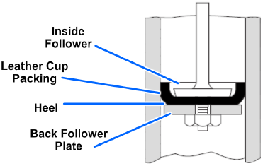
Cup packings resemble a cup or deep dish with a hole in the center for mounting (Figure 7-24). Cup seals are used exclusively to seal pistons in both low- and high-pressure hydraulic and pneumatic service. They are produced in leather, homogeneous synthetic rubber, and fabric-reinforced synthetic rubber. Although the cup packing lip flares outward, the rubbing contact is made at the lip only when the fluid pressure is low. As the fluid pressure increases, the cup heel expands outward until it contacts the cylinder wall, at which point high-pressure sealing is in effect. As the pressure loading shifts the sealing line to the cup heel, the lip is actually pulled into the cup and away from the cylinder wall. On the return stroke when the pressure is relaxed, the heel will shrink slightly, leaving only the lip in contact with the wall, avoiding unnecessary wear at the heel.
For reciprocating pistons, two cups installed back-to-back in separate glands are required.
Flange Packings
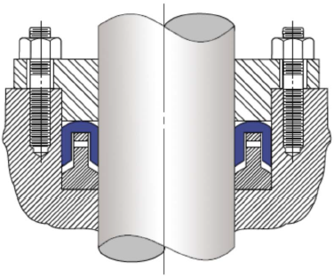
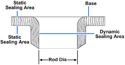
Flange packings are used exclusively in low-pressure, outside-packed installations, such as rod seals. The flange (sometimes called the hat) is made of leather, fabric-reinforced rubber, or homogeneous rubber. Lip sealing occurs only on the packing ID (Figure 7-25). Flange packings are generally used only for rod seals when other packings such as V-rings or U-seals cannot be used.
Dirt Exclusion Seals (Wipers and Scrapers)
Dirt exclusion devices are essential if a satisfactory life is to be obtained from most rod seals. The smooth finished moving rod surface, if not enclosed or protected by some sort of covering, will accumulate a coating of dust or abrasive material that will be dragged or carried into the packing assembly area on the return rod stroke. Exclusion devices called wipers or scrapers are designed to remove this coating. While the terms wiper and scraper are often used interchangeably, it is useful to reserve scraper for metal lip-type devices that remove heavily encrusted deposits of dirt or other abrasive material that would merely deflect a softer lip and be carried into the cylinder. Sometimes a rod will have both a scraper and a wiper, the former to remove heavy deposits and the latter to exclude any dust particles that remain. Whenever metallic scrapers are used with felt wipers in the same groove, the felt wiper must not be compressed nor restricted in any way that affects its function as a lubricator. A wiper installed in a seal assembly in a pneumatic application may remove too much oil from the rod, requiring some method of replacing the oil. A common remedy is to provide a periodically oiled felt ring between the wiper and the seal. Felt wipers provide lubrication to extended operating rods, thus increasing component wear life. These wipers are only used to provide lubrication to parts.
Much longer life could be obtained from most seals if proper attention were given to wipers and scrapers. Often, wiper or scraper failure is not noticed when a seal packing fails. As a result, only the packing is replaced, and the same worn wiper or scraper is reinstalled to destroy another packing. Check the wiper or scraper condition upon its removal. If the wiper is worn, dirty, or embedded with metallic particles, replace it with a new one. It is usually good practice to replace the wiper every time you replace the seal and even more frequently if the wiper is readily accessible without component disassembly. If replacements are not available, wash dirty wipers that are still in good condition with suitable solvent and reinstall them. Remember that a wiper or scraper is deliberately installed as a sacrificial part to protect and preserve the sealing packing. Therefore, from a user's standpoint, wipers and scrapers should be inspected and replaced as necessary.
Storage of Seals
Proper storage practices must be observed to prevent deformation and deterioration of seals. Most synthetic rubbers are not damaged by storage under ideal conditions. However, most synthetic rubbers will deteriorate when exposed to heat, light, oil, grease, fuels, solvents, thinners, moisture, strong drafts, or ozone (form of oxygen formed from an electrical discharge). Damage by exposure is magnified when rubber is under tension, compression, or stress. There are several conditions to be avoided, which include the following:
- Deformation as a result of improper stacking of parts and storage containers
- Creasing caused by force applied to corners and edges, and by squeezing between boxes and storage containers
- Compression and flattening as a result of storage under heavy parts
- Punctures caused by staples used to attach identification
- Deformation and contamination due to hanging the seals from nails or pegs. Seals should be kept in their original envelopes, which provide preservation, protection, identification, and cure date
- Contamination by piercing the sealed envelope to store O-rings on rods, nails, or wire hanging devices
- Contamination by fluids leaking from parts stored above and adjacent to the seal surfaces
- Contamination caused by adhesive tapes applied to seal surfaces. A torn seal package should be secured with a pressure-sensitive moisture proof tape, but the tape must not contact the seal surfaces
- Retention of overage parts as a result of improper storage arrangement or illegible identification. Seals should be arranged so the older seals are used first
PDH Classroom offers a continuing education course based on this sealing devices and materials reference page. This course can be used to fulfill PDH credit requirements for maintaining your PE license.
Now that you've read this reference page, earn credit for it!
