Chapter 8: Measurement and Pressure Control Devices
This page provides the chapter on hydraulic measurement and pressure control devices from the U.S. Navy's fluid power training course, NAVEDTRA 14105A, "Fluid Power," Naval Education and Training Professional Development and Technology Center, July 2015.
Other related chapters from the Navy's fluid power training course can be seen to the right.
Measurement and Pressure Control Devices
For safe and efficient operation, fluid power systems are designed to operate at a specific pressure and/or temperature, or within a pressure and/or temperature range.
You have learned that the lubricating power of hydraulic fluids varies with temperature and that excessively high temperatures reduce the life of hydraulic fluids. Additionally, you have learned that the materials, dimensions, and method of fabrication of fluid power components limit the pressure and temperature at which a system operates.
Most fluid power systems are provided with pressure gauges and thermometers for measuring and indicating the pressure and/or the temperature in the system. Additionally, various temperature and pressure switches are used to warn of an adverse pressure or temperature condition. Some switches will even shut the system off when an adverse condition occurs. These devices will be discussed in this chapter.
Learning Objectives
When you have completed this chapter, you will be able the do the following:
- Recognize the construction of the different types of fluid pressure indicators and thermometers.
- Recognize the uses of different types of fluid pressure indicators and thermometers.
- Recognize the construction of the different types of fluid pressure control switches.
- Identify the operational characteristics of fluid pressure control switches.
Pressure Gauges
The types of pressure gauges used in an engineering plant include Bourdon-tube gauges, bellows and diaphragm gauges, and manometers. Bourdon-tube gauges are generally used for measuring pressures above and below atmospheric pressure. Bellows and diaphragm gauges and manometers are generally used to measure pressures below 15 pounds per square inch gauge (psig). They are also used for low vacuum pressure. Low vacuum pressure is slightly less than 14.7 pounds per square inch absolute (psia). Often, pressure measuring instruments have scales calibrated in inches of water (inH2O) to allow greater accuracy.
On dial pressure gauges, set the adjustable red hand (if installed) at or slightly above the maximum normal operating pressure, or at or slightly below the minimum normal operating pressure. (Refer to Naval Ships' Technical Manual, Chapter 504, for specific instructions).
Bourdon-Tube Gauges
The device usually used to indicate temperature changes by its response to volume changes or to pressure changes is called a Bourdon tube. A Bourdon tube is a C-shaped, curved or twisted tube that is open at one end and sealed at the other (Figure 8-1). The open end of the tube is fixed in position, and the sealed end is free to move. The tube is more or less elliptical in cross section; it does not form a true circle. The tube becomes more circular when there is an increase in the volume or the internal pressure of the contained fluid. The spring action of the tube metal opposes this action and tends to coil the tube. Since the open end of the Bourdon tube is rigidly fastened, the sealed end moves as the pressure of the contained fluid changes.
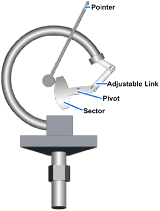
There are many types of Bourdon-tube gauges used in the Navy. The most common ones are the simplex, duplex, vacuum, compound, and differential pressure gauges. They operate on the principle that pressure in a curved tube has a tendency to straighten out the tube. This curved tube is made of bronze for pressures less than 200 pounds per square inch (psi) and of steel for pressures 200 psi and over.
Simplex Bourdon-Tube Gauge
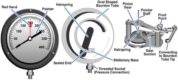
A simplex Bourdon tube installed in a gauge case is shown in Figure 8-2. Notice that the Bourdon tube is in the shape of the letter C and is welded or silver-brazed to the stationary base. The free end of the tube is connected to the indicating mechanism by a linkage assembly. The threaded socket, welded to the stationary base, is the pressure connection. When pressure enters the Bourdon tube, the tube tends to straighten out. The tube movement through linkage causes the pointer to move proportionally to the pressure applied to the tube. The simplex gauge is used for measuring the pressure of steam, air, water, oil, and similar fluids or gases.
Duplex Bourdon-Tube Gauge
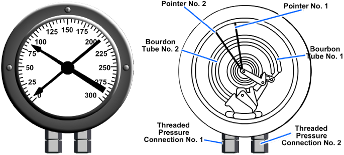
The duplex Bourdon-tube gauge (Figure 8-3) has two tubes and two separate gear mechanisms within the same case. A pointer is connected to the gear mechanism of each tube. Each pointer operates independently. Duplex gauges are normally used to show pressure drops between the inlet and outlet sides of lube oil and fuel oil strainers. If the pressure reading for the inlet side of a strainer is much greater than the pressure reading for the outlet side, it may be assumed that the strainer is likely to be dirty and is restricting the flow of lube oil and fuel oil through the strainer.
Bourdon-Tube Vacuum Gauge, Compound Gauge, and Differential Pressure Gauge
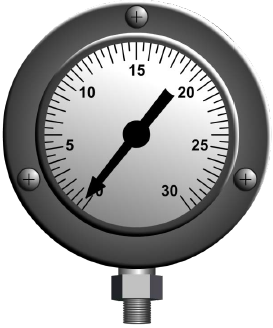
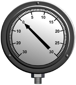
Bourdon-tube vacuum gauges are marked off in inches of mercury (inHg) (Figure 8-4). When a gauge is designed to measure both vacuum and pressure, it is called a compound gauge. Compound gauges are marked off in both in Hg and psig (Figure 8-5).
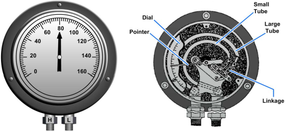
Differential pressure may also be measured with Bourdon-tube gauges. One of the types of Bourdon-tube differential pressure gauges is shown in Figure 8-6. This gauge has two Bourdon tubes, but only one pointer. The Bourdon tubes are connected in such a way that they show the pressure difference, rather than either of the two actual pressures indicated by the pointer.
Bellows Gauge
A bellows gauge contains an elastic element that is a convoluted unit that expands and contracts axially with changes in pressure. The pressure to be measured can be applied to the outside or inside of the bellows. However, in practice, most bellows measuring devices have the pressure applied to the outside of the bellows (Figure 8-7). Like Bourdon-tube elements, the elastic elements in bellows gauges are made of brass, phosphor bronze, stainless steel, beryllium-copper, or other metal that is suitable for the intended purpose of the gauge.
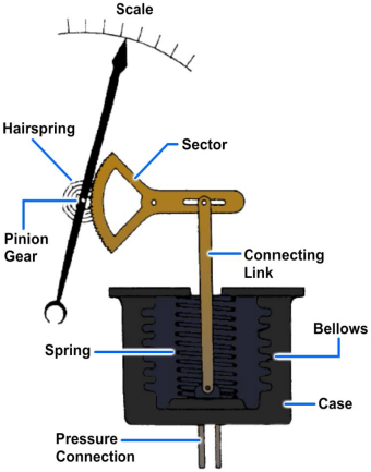
Most bellows gauges are spring-loaded; that is, a spring opposes the bellows, thus preventing full expansion of the bellows. Limiting the expansion of the bellows in this way protects the bellows and prolongs its life. In a spring-loaded bellows element, the deflection is the result of the force acting on the bellows and the opposing force of the spring.
Although some bellows instruments can be designed for measuring pressures up to 800 psig, their primary application aboard ship is in the measurement of low pressures or small pressure differentials.
Pressure Switches
It is often desirable to have an alarm sound a warning, a light give a signal, or an auxiliary control system energize or de-energize when a measured pressure reaches a certain minimum or maximum value. A pressure switch is the device commonly used for this purpose.
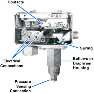
One of the simplest pressure switches is the single-pole, single-throw, quick-acting type shown in Figure 8-8. This switch is contained in a metal case that has a removable cover, an electrical connection, and a pressure-sensing connection. The switch contains a seamless metallic bellows located in its housing. Changes in the measured pressure cause the bellows to work against an adjustable spring. This spring determines the pressure required to actuate the switch. Through suitable linkage, the spring causes the contacts to open or close the electrical circuit automatically when the operating pressure falls below or rises above a specified value. A permanent magnet in the switch mechanism provides a positive snap on both the opening and closing of the contacts. The switch is constantly energized. However, it is the closing of the contacts that energizes the entire electrical circuit.
Another pressure switch is an electrohydraulic assembly that is used for shutting off the pump's motor whenever the system pressure exceeds a pre-determined maximum value (Figure 8-9). The switch is mounted on the pump housing so that the former's low pressure ports drain directly into the pump housing.
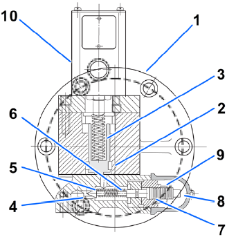
This pressure switch principally consists of a flange-mounted hydraulic valve to which is fixed a normally closed electrical limit switch. The valve consists of two hydraulically interconnected components. The pilot valve subassembly, which bolts on the bottom of the body (1), functions to sense system pressure continuously, and initiates pressure switch action whenever this pressure exceeds the adjusted setting of the pilot adjustment. System pressure is directed into the bottom port and is applied against the exposed tip of the pilot piston (5). This piston is held on its seat by compression from the piston spring (6) which is dependent on the position of the adjusting screw (8). Whenever the pressure causes a force large enough to raise the pilot piston from its seat, fluid flows through an interconnecting passage to the actuating piston (2) chamber. The accompanying fluid force raises the actuating piston against the force of spring (3) and causes depression of the extended switch plunger. This action disconnects the contained electrical switch, which may be connected into the pump motor's electric supply system.
Pressure switches come in many sizes and configurations depending on how they will be used.
Temperature Measuring Devices
Temperature is one of the basic engineering variables. Therefore, temperature measurement is essential to the proper operation of a shipboard engineering plant. As a watchstander, you will use both mechanical and electrical instruments to monitor temperature levels. You will frequently be called on to measure the temperature of steam, water, fuel, lubricating oil, and other vital fluids. In many cases, you will enter the results of measurements in engineering logs and records.
Thermometers (Mechanical)
Mechanical devices used to measure temperature are classified in various ways. In this section, we will discuss only the expansion thermometer types. Expansion thermometers operate on the principle that the expansion of solids, liquids, and gases has a known relationship to temperature change. The following types of expansion thermometers are discussed in this section:
- Liquid-in-glass thermometers
- Bimetallic expansion thermometers
- Filled-system thermometers
Liquid-in-Glass Thermometers
Liquid-in-glass thermometers are the oldest, simplest, and most widely used devices for measuring temperature. A liquid-in-glass thermometer (Figure 8-10) has a bulb and a very fine-bore capillary tube. The tube contains alcohol or some other liquid that uniformly expands or contracts as the temperature rises or falls. The selection of liquid is based on the temperature range for which the thermometer is to be used.
Almost all liquid-in-glass thermometers are sealed so atmospheric pressure does not affect the reading. The space above the liquid in this type of thermometer may be a vacuum, or this space maybe filled with an inert gas, such as nitrogen, argon, or carbon dioxide.
The capillary bore may be round or elliptical. In either case, it is very small; therefore, a relatively small expansion or contraction of the liquid causes a relatively large change in the position of the liquid in the capillary tube. Although the capillary bore has a very small diameter, the walls of the capillary tube are quite thick. Most liquid-in-glass thermometers have an expansion chamber at the top of the bore to provide a margin of safety for the instrument if it should accidentally overheat.
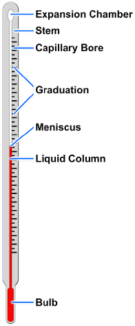
Liquid-in-glass thermometers may have graduations etched directly on the glass stem or placed on a separate strip of material located behind the stem. Many thermometers used in shipboard engineering plants have the graduations marked on a separate strip because this type is generally easier to read.
You will find liquid-in-glass thermometers in use in the oil and water test lab for analytical tests on fuel, oil, and water.
Bimetallic Expansion Thermometers
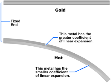
Bimetallic expansion thermometers make use of different metals that have different coefficients of linear expansion. The essential element in a bimetallic expansion thermometer is a bimetallic strip consisting of two layers of different metals fused together. When such a strip is subjected to temperature changes, one layer expands or contracts more than the other, thus tending to change the curvature of the strip.
The basic principle of a bimetallic expansion thermometer is shown in Figure 8-11. One end of a straight bimetallic strip is fixed in place. As the strip is heated, the other end tends to curve away from the side that has the greater coefficient of linear expansion.
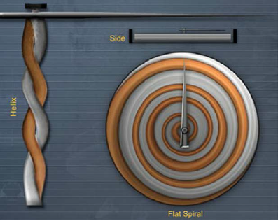
When used in thermometers, the bimetallic strip is normally wound into a flat spiral, a single helix, or a multiple helix (Figure 8-12). The end of the strip that is not fixed in position is fastened to the end of a pointer that moves over a circular scale. Bimetallic thermometers are easily adapted for use as recording thermometers. This function is accomplished by attaching a pen to the pointer and positioning the bimetallic thermometer so that it marks on a revolving chart.
Filled-System Thermometers
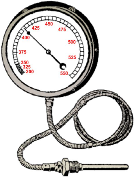
Generally, filled-system thermometers are used in locations where the indicating part of the instrument must be placed some distance away from the point where the temperature is to be measured. In a filled-system thermometer, temperature is converted into a mechanical motion caused by pressure or expansion. The components of a filled-system thermometer are comprised of the thermometer bulb, an expansion element, such as a Bourdon tube, diaphragm, capsule or bellows, and a capillary tube connecting the bulb and the expansion element. Some distant-reading thermometers have capillaries as long as 125 feet.
There are two basic types of filled-system thermometers used in Navy applications. One type has a Bourdon tube that responds primarily to changes in the volume of the filling fluid. The other type has a Bourdon tube that responds primarily to changes in the pressure of the filling fluid.
A distant-reading thermometer (Figure 8-13) consists of a hollow metal sensing bulb at one end of a small-bore capillary tube. The tube is connected to a Bourdon tube or other device that responds to volume changes or pressure changes. The system is partially or completely filled with a fluid that expands when heated and contracts when cooled. The fluid may be a gas, an organic liquid, or a combination of liquid and vapor.
Pyrometers
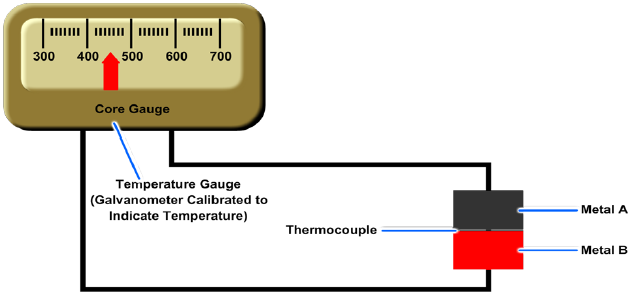
Pyrometers are used to measure temperature through a wide range, generally between 300 and 3,000 degrees Fahrenheit (°F). Aboard ship, pyrometers are used to measure temperatures in heat treatment furnaces, measure the exhaust temperatures of diesel engines, and for other similar purposes.
The pyrometer consists of a thermocouple and a meter (Figure 8-14). The thermocouple is made of two dissimilar metals joined together at one end. It produces an electric current when heat is applied at its joined end. The meter, calibrated in degrees, indicates the temperature at the thermocouple.
Electrical Temperature Measuring Devices
On newer propulsion plants, temperature readings are monitored at remote locations. Expansion thermometers provide indications at the machinery locations or on gauge panels in the immediate thermometer area. To provide remote indications at a central location, electrical measuring devices along with signal conditioners are used. The devices discussed in this section include the resistance temperature detectors (RTDs), resistance temperature elements (RTEs), and thermocouples. These devices sense variable temperatures at a given point in the system and transmit the signals to a remotely located indicator.
Resistance Temperature Detectors (RTDs)
The RTDs operate on the principle that electrical resistance changes in a predictable manner with changes in temperature. The elements of RTDs are made of nickel, copper, or platinum. Nickel and copper are used to measure temperatures below 600 °F. Platinum elements are used to measure temperatures above 600 °F. Two typical types of RTDs are shown in Figure 8-15.
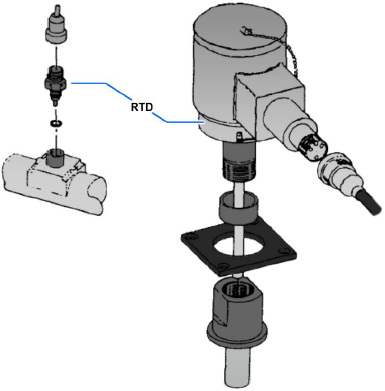
Like bimetallic thermometers, RTDs are usually mounted in thermowells. Thermowells protect the sensors from physical damage by keeping them isolated from the medium being measured. This arrangement also allows the RTD to be changed without securing the system in which it is mounted, making the maintenance job easier.
As temperature increases around an RTD, the corresponding resistance also increases proportionally. The temperature applied to an RTD, if known, gives a known resistance value. These resistance values can be found listed in tables in the manufacturers' technical manuals. Normally, only a few resistance values are given.
To test an RTD, it must be heated to a specific temperature. At this temperature, the resistance of the RTD should be at the resistance shown in the manufacturer's table. The most common method of heating an RTD is to use a pan of hot water and a calibrated thermometer. Some newer ships and repair activities test RTDs using a thermobulb tester. This method is more accurate and easier to use. For specific instructions, refer to the manufacturers' technical manuals supplied with the equipment.
The most common fault found with an RTD is either a short circuit or an open circuit. These faults can be quickly diagnosed by using digital display readings or data log printouts. By observing the reading or the printout, the indication will be either zero or a very low value. A malfunction of this type means a short circuit exists in either the RTD or its associated wiring. A very high reading, such as 300 °F on a 0 to 300 °F RTD, could indicate an open circuit. These readings should be compared to local thermometers. This precaution ensures that no abnormal conditions exist within the equipment that the RTD serves.
If an RTD is faulty, it should be replaced. Internal repairs cannot be made at the shipboard level. Until the faulty RTD is replaced, the watchstanders should be informed that the RTD is unreliable. The engine-room watchstanders should take local readings periodically to make sure the equipment is operating normally.
Resistance Temperature Elements (RTEs)
The RTEs are the most common type of temperature sensor found in gas turbine propulsion plants. The RTEs operate on the same principle as the RTDs. As the temperature of the sensor increases, the resistance of the RTE increases proportionally. All RTEs watchstanders encounter have a platinum element. They have an electrical resistance of 100 ohms at a temperature of 32 °F. Four different temperature ranges of RTEs are commonly used, and the probe sizes vary. The four temperature ranges and their corresponding probe sizes are as follows:
| Temperature Range [degree Fahrenheit] |
RTE Probe Length [inches] |
|---|---|
| −20 to +150 | 6 |
| 0 to +400 | 2, 4, and 10 |
| 0 to +1,000 | 2 |
| −60 to +500 | 6 |
Some RTEs are connected to remote mounted signal conditioning modules. These modules convert the ohmic value of the RTE to an output range of 4 to 20 milliamperes (mA) direct current (dc). However, most RTEs read their value directly into the propulsion electronics as an ohmic value.
The RTEs with temperature ranges from 0 to +400 °F and from −60 to +500 °F are commonly mounted in thermowells. Since an RTE can be changed without securing the equipment it serves, maintenance is simplified.
Gauge Snubbers
The irregularity of impulses applied to the fluid power system by some pumps or air compressors causes the gauge pointer to oscillate violently. This oscillation makes reading of the gauge not only difficult but often impossible. Pressure oscillations and other sudden pressure changes existing in fluid power systems will also affect the delicate internal mechanism of gauges and cause either damage to or complete destruction of the gauge. A pressure gauge snubber (Figure 8-16) is therefore installed in the line that leads to the pressure gauge.
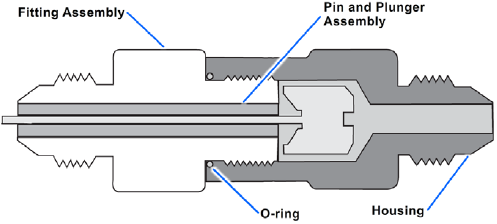
The purpose of the snubber is to dampen the oscillations and thus provide a steady reading and protection for the gauge. The basic components of a snubber are the housing, fitting assembly with a fixed orifice diameter, and a pin and plunger assembly. The snubbing action is obtained by metering fluid through the snubber. The fitting assembly orifice restricts the amount of fluid that flows to the gauge, thereby snubbing the force of a pressure surge. The pin is pushed and pulled through the orifice of the fitting assembly by the plunger, keeping it clean and at a uniform size.
PDH Classroom offers a continuing education course based on this measurement and pressure control devices reference page. This course can be used to fulfill PDH credit requirements for maintaining your PE license.
Now that you've read this reference page, earn credit for it!
