Stiffened Thin Pressure Vessels
This page provides the sections on the analysis of stiffened thin pressure vessels from the "Stress Analysis Manual," Air Force Flight Dynamics Laboratory, October 1986.
Other related chapters from the Air Force "Stress Analysis Manual" can be seen to the right.
- Simple Thin Pressure Vessels
- Stiffened Thin Pressure Vessels
- Thick Pressure Vessels
- Anisotropic Pressure Vessels
Nomenclature for Stiffened Thin Pressure Vessels
| A | = | α a/2 for stiffened cylinder |
| Ar | = | $$ { r^2 \over {b \over b'} \left({ e \over t_r }\right)^3 (1 - \mu^2) + {r^2 \over A_r'} } $$ |
| Ar' | = | minimum cross- sectional area of ring |
| Ast | = | cross section of stringer |
| a | = | distance between rings |
| B | = | β a/2 for stiffened cylinder |
| b | = | stringer spacing |
| b' | = | distance between adjacent edge of stringers |
| cs | = | distance from neutral axis of skin-stringer combination to outer fiber of skin |
| cst | = | distance from neutral axis of skin-stringer combination to outer fiber of stringer |
| D | = | EIsst for stiffened cylinder |
| d | = | Ast/bt for stiffened cylinder |
| E | = | modulus of elasticity |
| Ering | = | modulus of elasticity of ring |
| e | = | eccentricity of ring attachment to skin |
| Fbs | = | bending stress in skin |
| Fbst | = | bending stress in stringer |
| Fmer | = | meridional or axial stress |
| Fmermax | = | maximum meridional stress |
| Fmmer | = | meridional membrane stress |
| Fmt | = | circumferential membrane stress |
| Fstmer | = | meridional stress in stringer |
| Ft | = | tangential or circumferential stress |
| Isst | = | moment of inertia of sheet-stringer combination per inch of circumference |
| K | = | \( { \sqrt{t' E / D} \over 2r } \) for stiffened cylinder |
| M | = | bending moment |
| Msst | = | bending moment of skin-stringer combination per inch of circumference |
| Msstm | = | bending moment of skin-stringer combination per inch of circumference at midspan between rings |
| Msstr | = | bending moment of skin-stringer combination per inch of circumference at ring |
| P | = | \( { p ~r^2 \over t' E } \left[ 1 - { \mu ~t' \over 2(t + t_s) } \right] \) for stiffened cylinders |
| p | = | pressure difference (pi − po) |
| Q | = | \( { A_r E_{ring} ~a^3 \over 32 ~D ~r^2 } \) for stiffened cylinder |
| R | = | radius to centroid of minimum area of ring |
| r | = | radius to the inside of the skin of stiffened cylinder |
| T | = | pr/2 for stiffened cylinder |
| t | = | wall thickness |
| t' | = | \( { t + ts \over 1 + (1 - \mu^2) ts / t } \) for stiffened cylinder |
| ts | = | Ast/b for stiffened cylinder |
| α | = | \( \sqrt{ K + {T \over 4D} } \) for stiffened cylinder |
| β | = | \( \sqrt{ \left| K - {T \over 4D} \right| } \) for stiffened cylinder |
| δ | = | radial deflection of shell |
| δm | = | radial deflection of shell midway between rings |
| δr | = | radial deflection of shell at ring |
| μ | = | Poisson's ratio |
| Ωn | = | parameter in Figures 8-41 through 8-44 |
8.3.2 Stiffened Thin Pressure Vessels
This section treats of thin pressure vessels that are reinforced with stringers and/or rings.
8.3.2.1 Thin Cylindrical Pressure Vessels with Stringers Under Internal Pressure
Figure 8-37 shows a cross section of a thin cylindrical pressure vessel reinforced with stringers.
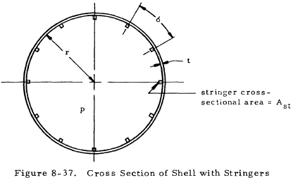
The axial stress in the shell is
and that in the stringer is
The circumferential stress is the same as that in a simple thin cylinder
8.3.2.1.1 Sample Problem - Thin Cylindrical Pressure Vessels with Stringers Under Internal Pressure
Given: The cylindrical pressure vessel shown in Figure 8-38.
Find: The stresses in the shell and stringers.

Solution: The distance between stringers is one-eighth the circumference of the cylinder.
From Equation (8-22). the meridional stress in the shell is
From Equation (8-24), the tangential stress in the shell is
$$ F_{mt} = {p r \over t} = {100 (20) \over 0.1} = 20,000 ~\text{psi} $$The only stress in the stringer is a meridional stress given by Equation (8-23).
We have a number of structural calculators to choose from. Here are just a few:
8.3.2.2 Thin Cylindrical Pressure Vessels with Rings Under Internal Pressure (Stringers Optional)
Figure 8-39 shows two views of a thin shell with rings and stringers and appropriate geometric parameters. An enlarged view of the section of the ring is shown in Figure 8-40.
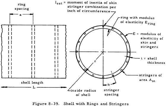
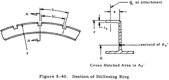
The definition of the following parameters facilitates the description of pressure vessel behavior.
| $$ d = {A_{st} \over bt} $$ |
| $$ T = {pr \over 2} $$ |
| $$ t_s = { A_{st} \over b } $$ |
| $$ t' = { t + t_s \over 1 + (1 - \mu^2) {t_s \over t} } $$ |
| D = EIsst of sheet stringer combination per inch of circumference |
| $$ K = { \sqrt{ t' E / D} \over 2r } $$ |
| $$ \alpha = \sqrt{ K + {T \over 4D} } $$ |
| $$ \beta = \sqrt{ \left| K - {T \over 4D} \right| } $$ |
| $$ A = { \alpha a \over 2 } $$ |
| $$ B = { \beta a \over 2 } $$ |
| $$ P = { p r^2 \over t' E } \left[ 1 - { \mu t' \over 2 (t + t_s) } \right] $$ |
| $$ A_r = { r^2 \over {b \over b'} \left({e \over t_r}\right)^3 (1 - \mu^2) + { r^2 \over A_r' } } $$ |
| $$ Q = { A_r E_r a^3 \over 32 D r^2 } $$ |
The deflections and moments on the shell at the ring and at midspan between rings are dependent on the relationship between K and T/4D. Two conditions are possible -- K ≥ T/4D and K < T/4D.
If K ≥ T/4D, the radial deflections of the shell at the ring (δr) and midway between the rings (δm) are given by Equations (8-25) and (8-26). In this case, the bending moments of the skin stringer combination per inch of circumference at the ring (Msstr) and midway between rings (Msstm) are given by Equations (8-27) and (8-28).
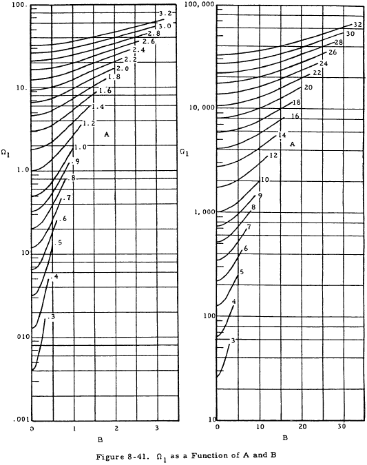
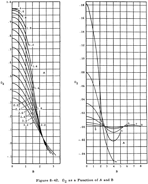
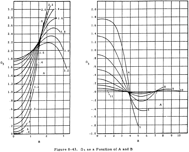
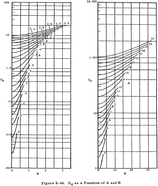
In the above equations, Ωn values may be obtained from Figures 8-41 through 8-44.
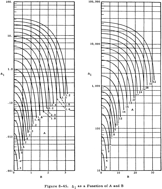
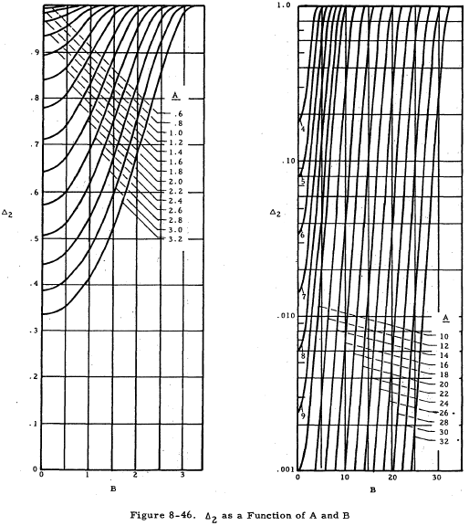
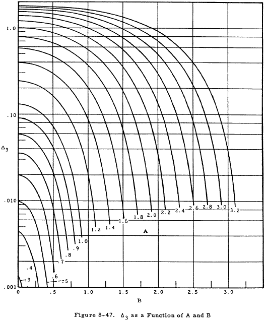
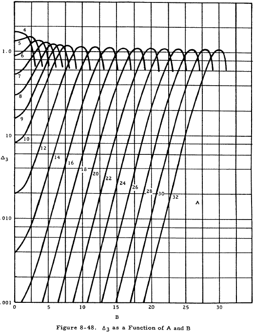
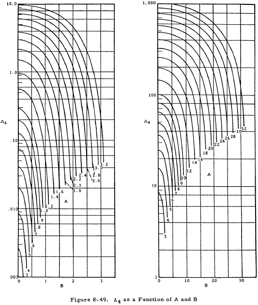
If K < T/4D, the equations for deflections and moments on the shell are the same as Equations (8-25) through (8-28) except that the Ωn terms are replaced by Δn terms. These Δn terms are given as functions of A and B in Figures 8-45 through 8-49.
The skin of a thin cylindrical pressure vessel with rings and stringers has stresses that are uniform throughout their thickness and that are given by
and
In addition, the skin has a maximum axial bending stress of
where cs is the distance from the neutral axis of the skin-stringer combination to the outer fiber of the skin.
The stringers have a uniform axial stress given by
in addition to a maximum bending stress of
where cst is the distance from the neutral axis of the skin-stringer combination to the outer fiber of the stringer.
The rings have a circumferential stress given by
We have a number of structural calculators to choose from. Here are just a few:
8.3.2.2.1 Sample Problem - Stiffened Thin Cylindrical Pressure Vessel with Internal Pressure
Given: A shell reinforced with rings and stringers under an internal pressure of 15 psi. The vessel parameters as shown in Figures 8-39 and 8-40 are as follows:
r = 66 in, a = 11.34 in, t = 0.030 in, b = 2.7 in, Ast = 0.1048 in2, Isst = 0.00493 in4, R = 63.2 in, tr = 0.040 in, e = 0.35 in, b' = 2.2 in, Ar' = 0.276 in2, cs = 0.208 in to skin, cst = 0.572 in, E = Ering = 17×106 psi, μ = 0.316, therefore 1 − μ2 = 0.9.
Find: The stresses in the skin, stringers, and rings.
Solution: From the definitions of parameters in Section 8.3.2.2,
| $$ d = {A_{st} \over bt} = {0.1048 \over 2.7 (0.030)} = 1.29 $$ |
| $$ T = {pr \over 2} = {15(66) \over 2} = 495 $$ |
| $$ t_s = { A_{st} \over b } = { 0.1048 \over 2.7 } = 0.0388 $$ |
|
$$ t' = { t + t_s \over 1 + (1 - \mu^2) {t_s \over t} } = { 0.030 + 0.0388 \over 1 + 0.9 (0.0388/0.030) } = 0.0318 $$
|
| D = EIsst = 17×106 (0.00493) = 8.38×10⁴ |
|
$$ K = { \sqrt{ t' E / D} \over 2r } = { \sqrt{ 0.0318 (17 \times 10^6) / (8.38 \times 10^4)} \over 2 (66) } = 0.01925 $$
|
| $$ {T \over 4D} = {495 \over 4(8.38 \times 10^4)} = 0.001477 $$ |
|
$$ \alpha = \sqrt{ K + {T \over 4D} } = \sqrt{ 0.01925 + 0.001477 } = 0.144 $$
|
|
$$ \beta = \sqrt{ \left| K - {T \over 4D} \right| } = \sqrt{ \left| 0.01925 - 0.001477 \right| } = 0.1333 $$
|
| $$ A = { \alpha a \over 2 } = {0.144 (11.34) \over 2} = 0.817 $$ |
| $$ B = { \beta a \over 2 } = {0.1333 (11.34) \over 2} = 0.756 $$ |
|
$$ P = { p r^2 \over t' E } \left[ 1 - { \mu t' \over 2 (t + t_s) } \right] = { 15 (66)^2 \over 0.0318 (17 \times 10^6) } \left[ 1 - { 0.316 (0.318) \over 2 (0.030 + 0.038) } \right] = 0.1122 $$
|
|
$$ A_r = { r^2 \over {b \over b'} \left({e \over t_r}\right)^3 (1 - \mu^2) + { r^2 \over A_r' } } = { (66)^2 \over {2.7 \over 2.2} \left({0.35 \over 0.40}\right)^3 (0.9) + { (63.2)^2 \over 0.276 } } = 0.286 $$
|
|
$$ Q = { A_r E_{ring} a^3 \over 32 D r^2 } = { 0.286 (17 \times 10^6) (11.34)^3 \over 32 (8.38 \times 10^4) (66)^2 } = 0.607 $$
|
Since K > T/4D, Equations (8-25) through (8-28) may be used to obtain deflections and moments. From Figures 8-41 through 8-44 with A = 0.817 and B = 0.756,
Ω1 = 0.76, Ω2 = 0.94, Ω3 = 0.24, and Ω4 = 0.49
These values may now be substituted into Equations (8-25) through (8-28) to obtain the following:
| Deflection at ring |
$$ \delta_r = { -P \over 1 + {Q \over \Omega_1} } = { -0.1122 \over 1 + {0.607 \over 0.76} } = 0.0624 ~\text{in. (outward)} $$
|
| Deflection at midspan |
$$ \delta_m = -P \left( 1 - { \Omega_2 \over 1 + {\Omega_1 \over Q} } \right) = -0.1122 \left( 1 - { 0.94 \over 1 + {0.76 \over 0.607} } \right) = -0.0654 ~\text{in. (outward)} $$
|
| Moment at ring |
$$ M_{sstr} = { 4 ~PD ~\Omega_4 \over a^2 \left( 1 + {\Omega_1 \over Q} \right) } = { 4 (0.1122) (8.38 \times 10^4) (0.49) \over (11.34)^2 \left( 1 + {0.76 \over 0.607} \right) } = 63.7 ~\text{in-lb/in} $$
|
| Moment at midspan |
$$ M_{sstm} = { -M_{ssr} \Omega_3 \over \Omega_4 } = { -63.7 (0.24) \over (0.49) } = -31.2 ~\text{in-lb/in} $$
|
Stresses in Skin
The stresses in the skin consist of
- a meridional membrane stress, Fmmer
- an axial bending stress Fbs, and
- a tangential membrane stress Fmt.
These must be computed at both the midspan and the ring. From Equation (8-29),
At the midspan,
At the ring,
From Equation (8-31),
$$ F_{bs} = { M c_s \over I_{sst} } = { M (0.208) \over 0.00493 } = 42.1 ~M $$At the midspan,
$$ F_{bs} = 42.1 ~M_{sstm} = 42.1 (31.2) = 1,320 ~\text{psi} $$At the ring,
$$ F_{bs} = 42.1 ~M_{sstr} = 42.1 (-63.7) = -2,680 ~\text{psi} $$From Equation (8-30),
At the midspan,
$$ F_{mt} = 2,410 - 273,000 (0.0654) = 20,260 ~\text{psi} $$At the ring,
$$ F_{mt} = 2,410 - 273,000 (0.0624) = 19,440 ~\text{psi} $$The maximum meridional stress in the skin at the midspan is given by
and that at the ring is
The critical stress occurs in the skin at the midspan where both the meridional and circumferential stresses are greatest.
Stresses in Stringer
The stresses in the stringers consist of
- a uniform axial stress, Fstmer and
- an axial bending stress, Fbst·
From Equation (8-32),
At the midspan
At the ring,
From Equation (8-33),
$$ F_{bst} = { M c_{st} \over I_{ss} } = { M (0.572) \over 0.00493 } = 116 ~M $$At the midspan,
$$ F_{bst} = 116 ~M_{sstm} = 116 (-31.2) = -3,730 ~\text{psi} $$At the ring,
$$ F_{bst} = 116 ~M_{sstr} = 116 (63.7) = 7,410 ~\text{psi} $$The maximum stress in the stringers is given by
$$ F_{mermax} = F_{stmer} + F_{bst} $$This occurs at the ring where
$$ F_{mermax} = 4,510 + 7,410 = 11,910 ~\text{psi} $$Stresses in Ring
The rings have a circumferential stress Ft. From Equation (8-34),
