Trusses
This page provides the chapter on the analysis of trusses from the "Stress Analysis Manual," Air Force Flight Dynamics Laboratory, October 1986.
4.1 Introduction to Trusses
A truss is a structure composed entirely of two-force members; that is, the members that have two equal and opposite forces applied at two points. Thus, since the members do not exert any torque on each other at the joints, they are considered to be pin connected. However, welded and riveted joints may be considered to be pinned joints if the member is so long compared with its lateral dimensions that the connection can exert little restraint against rotation.
Section 4.3 discusses statically determinate trusses, and Section 4.4 treats statically indeterminate trusses.
4.2 Nomenclature for Trusses
| A | = | cross-sectional area of truss member |
| E | = | modulus of elasticity |
| L | = | length of truss member |
| P | = | force in truss member |
| R | = | reaction force |
| u | = | force in truss member due to a unit load |
| X | = | force in redundant member of a truss |
| δ | = | deflection |
4.3 Statically Determinate Trusses
4.3.1 Introduction to Statically Determinate Trusses
The forces carried by the members of a statically determinate truss may be determined by passing sections through certain members and applying the equations of statics. The method of joints (Section 4.3.2) consists of choosing these sections so that they completely surround a single joint. If the sections that are chosen do not surround a single joint, the procedure used is referred to as the method of sections (Section 4.3.4). This method is especially useful if it is desired to determine the load in only certain members. In many cases, a combination of the method of joints and the method of sections may be advantageous in the analysis of a given truss.
Before either of these methods may be applied, the reaction forces on the truss should be determined by the equations of statics.
Deflections in statically determinate trusses are treated in Section 4.3.6.
4.3.2 Application of the Method of Joints to Statically Determinate Trusses
If a truss as a whole is in equilibrium, each joint in the truss must likewise be in equilibrium. The method of joints consists of isolating a joint as a free body and applying the equilibrium equations to the resulting force system. Since the forces in the members at a truss joint intersect at a common point, only two equations of equilibrium may be written for each joint in a planar truss. Thus, only two unknowns may exist at a joint and the procedure is to start at a joint where only two unknowns exist and continue progressively throughout the truss joint by joint. This procedure is illustrated in Section 4.3.3.
We have a number of structural calculators to choose from. Here are just a few:
4.3.3 Sample Problem - Application of the Method of Joints to Statically Determinate Trusses
Given: The truss shown in Figure 4-1.
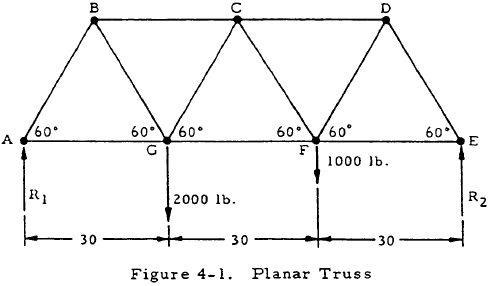
Find: The forces in all of the members.
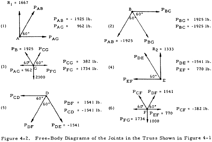
Solution: Applying the equations of statics to the entire truss gives R1 = 1667 lb and R2 = 1333 lb. Free body diagrams may be drawn for the joints in the order shown in Figure 4-2 and solved for the forces in the members. Summarizing, if tensile forces are taken as positive, the forces in the members are
| PAB = -1925 lb | PCF = -382 lb |
| PAG = 962 lb | PCG = 382 lb |
| PBC = -1925 lb | PDE = -1541 lb |
| PBG = 1925 lb | PDF = 1541 lb |
| PCD = -1541 lb | PEF = 770 lb |
| PFG = 1734 lb |
4.3.4 Application of the Method of Sections to Statically Determinate Trusses
The method of sections consists of breaking a truss up by a section and applying the equilibrium equations to the resulting portions of the truss. This method is preferable to the method of joints if the force on some interior member is desired, since the necessity of calculating the forces on other members may be eliminated. This advantage of the method of sections is illustrated in Section 4.3.5.
4.3.5 Sample Problem - Statically Determinate Trusses by the Method of Sections
Given: The truss shown in Figure 4-1.
Find: The force in member FG.
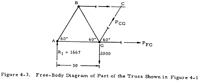
Solution: From statics, R1 = 1667 lb and R2 = 1333 lb. By drawing a section through members BC, CG, and FG, the free body shown in Figure 4-3 is obtained. Summing moments about point C gives PFG (30 sin60°) - 1667(45) + 2000(15). Solving gives PFG = 1734 lb.
4.3.6 Deflections in Statically Determinate Trusses
The basic equation for the deflection of statically determinate trusses is
In this equation, L, A, and E are the length, cross-sectional area, and modulus of elasticity of each of the members of the truss. P is the force due to applied loads of a member of the truss, and u is the force in a member of the truss due to a unit load applied in the direction of the desired deflection at the point whose deflection is desired. The application of this equation is illustrated in Section 4.3.7.
4.3.7 Sample Problem - Deflections in Statically Determinate Trusses
Given: The truss shown in Figure 4-4.
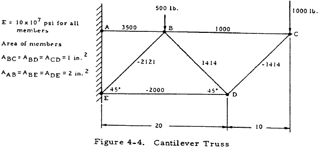
Find: The vertical deflection of joint D.
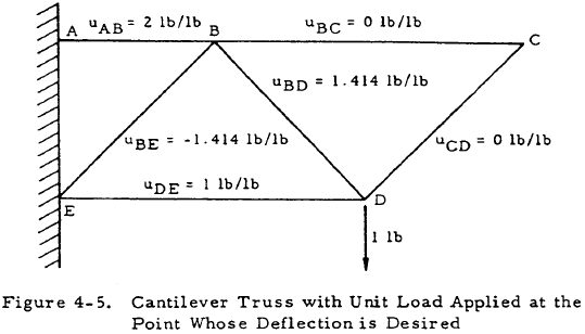
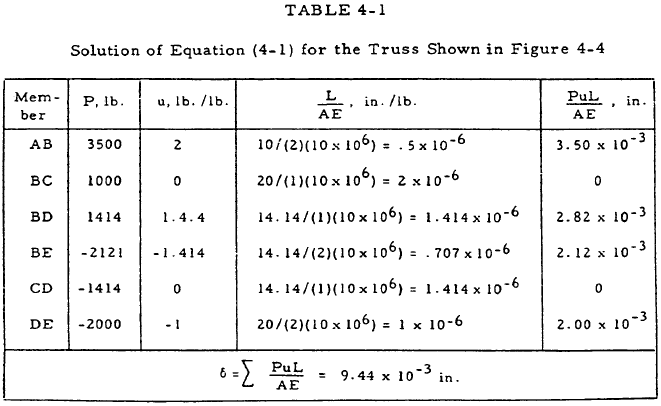
Solution: The forces in the members may be found to be: PAB = 3500 lb, PBC = 1000 lb, PBD = 1414 lb, PBE = -2121 lb, PCD = -1414 lb, and PDE = -2000 lb. The truss may be redrawn with a unit load in the direction of the desired deflection at joint D as shown in Figure 4-5. The forces in the members are again calculated with the results shown in Figure 4-5. Equation (4-1) may now be solved as shown in Table 4-1.
We have a number of structural calculators to choose from. Here are just a few:
4.4 Statically Indeterminate Trusses
4.4.1 Introduction to Statically Indeterminate Trusses
If a truss is statically indeterminate, deflection equations must be applied in addition to equilibrium equations to determine the forces in all of the members. Section 4.4.2 treats trusses with a single redundancy, and trusses with multiple redundancies are treated in Section 4.4.4.
4.4.2 Statically Indeterminate Trusses with a Single Redundancy
Trusses with a single redundancy may be treated by removing one member so that a statically determinate truss is obtained. This member is replaced by the unknown force exerted by this member, Xa. One equation may be written for the deflection of the statically determinate truss due to the applied loads including X, and another equation may be written for the deflection of the removed member due to the unknown force, X. These two equations may then be solved simultaneously to find X. Once X has been found, the forces in the other members of the truss may be obtained by the equations of statics. This procedure is illustrated in Section 4.4.3.
4.4.3 San1ple Problem - Statically Indeterminate Trusses with a Single Redundancy
Given: The truss shown in Figure 4-6.
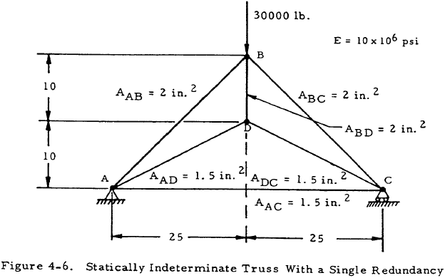
Find: The force on member AC.
Solution: The truss may be redrawn with member AC replaced by the force resisted by this member, X, as shown in Figure 4-7. The force in any member of the truss, P, may be obtained by the superposition of the force due to the vertical loads alone, Po, and that due to the horizontal loads alone. This latter force may be given as Xu where u is the force in a member of the truss due to a unit horizontal load applied at points A and C. Thus,
$$ P = P_o + X_u $$By substituting this expression for P into Equation (4-1), the horizontal deflection between points A and C is
The terms \( \sum { P_o ~u ~L \over A ~E } \) and \( \sum { u^2 L \over A ~E } \) are computed in Table 4-2. Thus,
$$ \delta = -0.5645 + 47.63 \times 10^{-6} ~X $$From the deflection equation for bar AC,
$$ \delta = { -X ~L_{AC} \over A_{AC} ~E } = { -X (50) \over 1.5 (10 \times 10^6) } = 3.33 \times 10^{-6} ~X $$Solving the last two equations simultaneously gives
$$ X = 12730 ~\text{lb} $$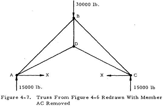
| Member | Po, lb | u, lb/lb | \({L \over AE}\) in/lb | \({P_o u L \over AE}\) in | \({u^2 L \over AE}\) in/lb |
| AB | -32000 | 1.785 | 1.600 x 10⁻⁶ | -0.0915 | 5.11 x 10⁻⁶ |
| AD | 26900 | -3.0 | 1.795 x 10⁻⁶ | -0.1450 | 16.15 x 10⁻⁶ |
| BC | -32000 | 1.785 | 1.600 x 10⁻⁶ | -0.0915 | 5.11 x 10⁻⁶ |
| BD | 20000 | -2.23 | 0.67 x 10⁻⁶ | -0.0292 | 3.32 x 10⁻⁶ |
| CD | 26900 | -3.0 | 1.795 x 10⁻⁶ | -0.1450 | 16.15 x 10⁻⁶ |
| \( \sum { P_o u L \over AE } \) = -0.5150 | \( \sum { u^2 L \over AE } \) = 47.63 x 10⁻⁶ in/lb | ||||
4.4.4 Statically Indeterminate Trusses with Multiple Redundancies
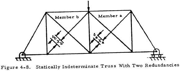
The analysis of trusses with more than one redundant is similar to that for a truss with one redundant. The first step is to remove redundant members or reactions in order to obtain a statically determinate base structure. The deflections of the statically determinate base structure in the directions of the redundants may then be calculated in terms of the redundant forces, and equated to the known deflections. For example, consider the truss in Figure 4-8. Members a and b may be removed to obtain a statically determinate base structure. The final force, P, in any member may be obtained by superposing the forces due to the applied loads and redundant forces. Thus,
where Po is the force in a member of the statically determinate base structure due to the external load and ua and ub are the forces in a member of the statically determinate base structure due to unit loads applied in members a and b, respectively. Applying this equation to members a and b, respectively, gives
and
where L, A, and E are properties of the members of the statically determinate base structure and P the force in a member of the base structure. Substituting Equation (4-3) into Equations (4-4) and (4-5) gives
and
In addition,
and
Equations (4-6) through (4-9) may be solved simultaneously to obtain the forces in the redundant members. Once this has been done, Equation (4-3) may be applied to obtain the forces in the other members.
Also,
These equations may be solved simultaneously to obtain the forces in the redundant members.
