Lug Analysis
This page provides the chapter on lug analysis from the "Stress Analysis Manual," Air Force Flight Dynamics Laboratory, October 1986.
Other related chapters from the Air Force "Stress Analysis Manual" can be seen to the right.
- Lug Analysis
- Lug Fatigue Analysis
9.1 Introduction to Lug Analysis
Lugs are connector-type elements widely used as structural supports for pin connections. In the past, the lug strength was overdesigned since weight and size requirements were for the most part unrestricted. However, the refinement of these requirements have necessitated conservative methods of design.
This section presents static strength analysis procedures for uniformly loaded lugs and bushings, for double shear joints, and for single shear joints, subjected to axial, transverse, or oblique loading. Also listed is a section which applies to lugs made from materials having ultimate elongations of at least 5% in any direction in the plane of the lug. Modifications for lugs with less than 5% elongation are also presented. In addition, a short section on the stresses due to press fit bushings is presented.
9.2 Lug Analysis Nomenclature
| Fbru.L | = | Lug ultimate bearing stress |
| Fbry.L | = | Lug yield bearing stress |
| Ftux | = | Cross grain tensile ultimate stress of lug material |
| Ftyx | = | Cross grain tensile yield stress of lug material |
| Fbru | = | Allowable ultimate bearing stress, MHBS |
| Fbry | = | Allowable yield bearing stress, MHBS |
| Ftu | = | Ultimate tensile stress |
| Fnu.L | = | Allowable lug net-section tensile ultimate stress |
| Fny.L | = | Allowable lug net-section tensile yield stress |
| Fbry.B | = | Allowable bearing yield stress for bushings |
| Fbru.B | = | Allowable bearing ultimate stress for bushings |
| Fcy.B | = | Bushing compressive yield stress |
| Fsu.P | = | Ultimate shear stress of the pin material |
| Ftu.P | = | Pin ultimate tensile stress |
| Ftu.T | = | Allowable ultimate tang stress |
| Fbr.max.L | = | Maximum lug bearing stress |
| Fbr.max.B | = | Maximum bushing bearing stress |
| Fs.max.P | = | Maximum pin shear stress |
| Fb.max.P | = | Maximum pin bending stress |
| Pbru.L | = | Allowable lug ultimate bearing load |
| Pnu.L | = | Allowable lug net-section ultimate load |
| Pu.B | = | Allowable bushing ultimate load |
| Pu.L | = | Allowable design ultimate load |
| Pu.L.B | = | Allowable lug-bushing ultimate load |
| Pus.P | = | Pin ultimate shear load |
| Pub.P | = | Pin ultimate bending load |
| Pub.P.max | = | "Balanced design" pin ultimate bending load |
| Pall | = | Allowable joint ultimate load |
| PT | = | Lug tang strength |
| Ptru.L | = | Allowable lug transverse ultimate load |
| Ptru.B | = | Allowable bushing transverse ulti.Inate load |
| Kn | = | Net-tension stress coefficient |
| Kb.P | = | Plastic bending coefficient for pin |
| Kb.T | = | Plastic bending coefficient for tang |
| Kbr.L | = | Plastic bearing coefficient for lug |
| Kb.L | = | Plastic bending coefficient for lug |
| Ktru | = | Transverse ultimate load coefficient |
| Ktry | = | Transverse yield load coefficient |
| Mmax.P | = | Maximum pin bending moment |
| Mu.P | = | Ultimate pin failing moment |
| A | = | Area, in2 |
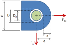
| a | = | Distance from edge of hole to edge of lug, inches |
| B | = | Ductility factor for lugs with less than 5% elongation |
| b | = | Effective bearing width, inches |
| D | = | Hole diameter of pin diameter, inches |
| E | = | Modulus of elasticity, psi |
| e | = | Edge distance, inches |
| f | = | Stress, psi |
| g | = | Gap between lugs, inches |
| h1..h4 | = | Edge distances in transversely loaded lug, inches |
| hav | = | Effective edge distance in transversely loaded lug |
| K | = | Allowable stress (or load) coefficient |
| M | = | Bending moment, in.-lbs. |
| P | = | Load, lbs. |
| tB | = | Bushing wall thickness, inches |
| t | = | Lug thickness, inches |
| w | = | Lug width, inches |
| α | = | Angle of load to axial direction, degrees |
| ϵ | = | Strain, inches/inch |
| ρ | = | Density, lbs/in3 |
9.3 Lug and Bushing Strength Under Uniform Axial Load
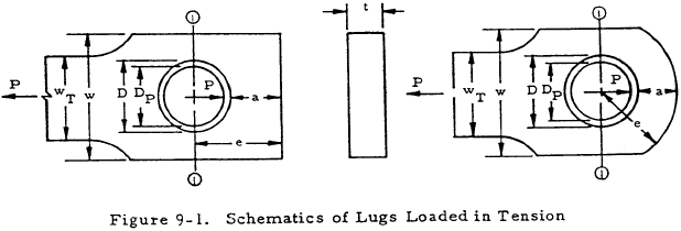
Axially loaded lugs in tension must be checked for bearing strength and for net-section strength. The bearing strength of a lug loaded in tension, as shown in Figure 9-1, depends largely on the interaction between bearing, shear-out, and hoop-tension stresses in the part of the lug ahead of the pin. The net-section of the lug through the pin must be checked against net-tension failure. In addition, the lug and bushing must be checked to ensure that the deformations at design yield load are not excessive.
9.3.1 Lug Bearing Strength Under Uniform Axial Load
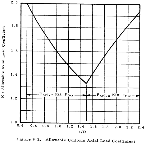
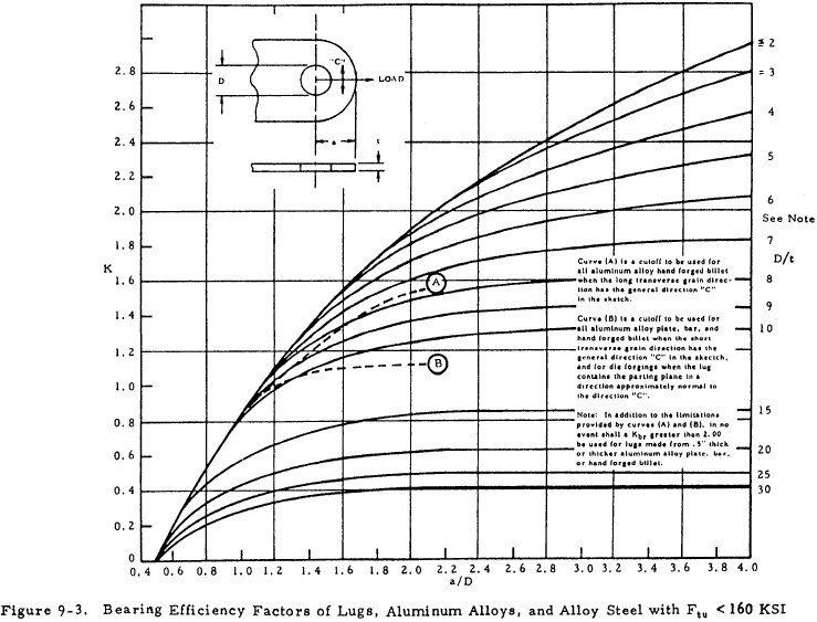
The bearing stresses and loads for lug failure involving bearing, shear-tearout, or hoop tension in the region forward of the net-section in Figure 9-1 are determined from the equations below, with an allowable load coefficient (K) determined from Figures 9-2 and 9-3. For values of e/D less than 1.5, lug failures are likely to involve shear-out or hoop tension; and for values of e/D greater than 1.5, the bearing is likely to be critical. Actual lug failures may involve more than one failure mode, but such interaction effects are accounted for in the values of K. The lug ultimate bearing stress (Fbru.L) is
The graph in Figure 9-2 applies only to cases where D/t is 5 or less, which covers most of the cases. If D/t is greater than 5, there is a reduction in strength which can be approximated by the curves in Figure 9-3. The lug yield bearing stress (Fbry.L) is
The allowable lug ultimate bearing load (Pbru.L) for lug failure in bearing, shear-out, or hoop tension is
Pbru.L/Dt should not exceed either Fbru or 1.304Fbry, where Fbru and Fbry are the allowable ultimate and yield bearing stresses for the lug material for e/D = 2.0, as given in MIL-HDBK-5 or other applicable specification.
Equations (9-3a) and (9-3b) apply only if the load is uniformly distributed across the lug thickness. If the pin is too flexible and bends excessively, the load on the lug will tend to peak up near the shear faces and possibly cause premature failure of the lug.
A procedure to check the pin bending strength in order to prevent premature lug failure is given in Section 9.4 entitled "Double Shear Joint Strength Under Uniform Axial Load."
9.3.2 Lug Net-Section Strength Under Uniform Axial Load
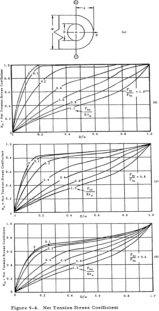
The allowable lug net-section tensile ultimate stress (Fnu.L) on Section 1-1 in Figure 9-4a is affected by the ability of the lug material to yield and thereby relieve the stress concentration at the edge of the hole.
Kn, the net-tension stress coefficient, is obtained from the graphs shown in Figure 9-4 as a function of the ultimate and yield stress and strains of the lug material in the direction of the applied load. The ultimate strain (ϵu) can be obtained from MIL-HDBK-5.
The allowable lug net-section tensile yield stress (Fny.L) is
The allowable lug net-section ultimate load (Pnu.L) is
9.3.3 Lug Design Strength Under Uniform Axial Load
The allowable design ultimate load for the lug (Pu.L) is the lower of the values obtained from Equations (9-3) and (9-6).
| $$ P_{u.L} \le $$ | $$ P_{bru.L} $$ | (Equations (9-3a) and (9-3b)), or |
| $$ P_{nu.L} $$ | (Equations (9-6a) and (9-6b)) |
9.3.4 Bushing Bearing Strength Under Uniform Axial Load
The allowable bearing yield stress for bushings (Fbry.B) is restricted to the compressive yield stress (Fcy.B) of the bushing material, unless higher values are substantiated by tests.
The allowable bearing ultimate stress for bushings (Fbru.B) is
The allowable bushing ultimate load (Pu.B) is
This assumes that the bushing extends through the full thickness of the lug.
9.3.5 Combined Lug-Bushing Design Strength Under Uniform Axial Load
The allowable lug-bushing ultimate load (Pu.L.B) is the lower of the loads obtained from Equations (9-7) and (9-9).
| $$ P_{u.L.B} \le $$ | $$ P_{u.L} $$ | (Equation (9-7)), or |
| $$ P_{u.B} $$ | (Equation (9-9)) |
Need a Lug Calculator?
Try this lug calculator based on the methodology described here.
- Allows for axial, transverse, or oblique loading
- Performs calculations for lug strength, pin strength, and double shear joint strength
9.4 Double Shear Joint Strength Under Uniform Axial Load
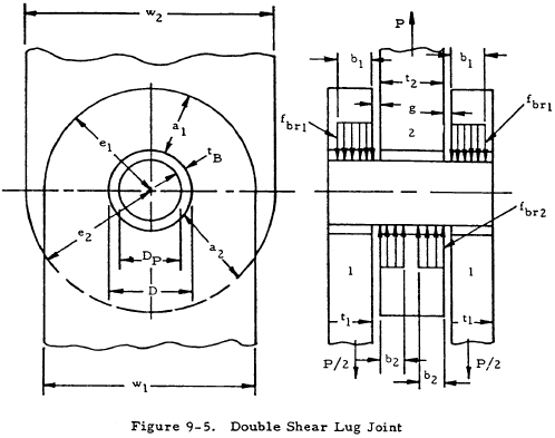
The strength of a joint such as the one shown in Figure 9-5 depends on the lug-bushing ultimate strength (Pu.L.B) and on the pin shear and pin bending strengths.
9.4.1 Lug-Bushing Design Strength for Double Shear Joints Under Uniform Axial Load
The allowable lug-bushing ultimate load (Pu.L.B) for the joint is computed, using Equation (9-10). For the symmetrical joint shown in the figure, Equation (9-10) is used to calculate the ultimate load for the outer lugs and bushings (2Pu.L.B.1) and the ultimate load for the inner lug and bushing (Pu.L.B.2). The allowable value of Pu.L.B for the joint is the lower of these two values.
| $$ P_{u.L.B} \le $$ | $$ 2 P_{u.L.B.1} $$ | (Equation (9-10)), or |
| $$ P_{u.L.B.2} $$ | (Equation (9-10)) |
9.4.2 Pin Shear Strength for Double Shear Joints Under Uniform Axial Load
The pin ultimate shear load (Pus.P) for the symmetrical joint shown in Figure 9-5 is the double shear strength of the pin:
where Fsu.P is the ultimate shear stress of the pin material.
9.4.3 Pin Bending Strength for Double Shear Joints Under Uniform Axial Load
Although actual pin bending failures are infrequent, excessive pin deflections can cause the load in the lugs to peak up near the shear planes instead of being uniformly distributed across the lug thickness, thereby leading to premature lug or bushing failures at loads less than those predicted by Equation (9-11). At the same time, however, the concentration of load near the lug shear planes reduces the bending arm and, therefore, the bending moment in the pin, making the pin less critical in bending. The following procedure is used in determining the pin ultimate bending load.
Assume that the load in each lug is uniformly distributed across the lug thickness (b1 = t1, and 2b2 = t2). For the symmetrical joint shown in Figure 9-5, the resulting maximum pin bending moment is
The ultimate failing moment for the pin is
where kb.P is the plastic bending coefficient for the pin. The value of kb.P varies from 1.0 for a perfectly elastic pin to 1.7 for a perfectly plastic pin, with a value of 1.56 for pins made from reasonably ductile materials (more than 5% elongation).
The pin ultimate bending load (Pub.P) is, therefore,
If Pub.P is equal to or greater than either Pu.L.B (Equation (9-11)) or Pus.P (Equation (9-12)), then the pin is a relatively strong pin that is not critical in bending, and no further pin bending calculations are required. The allowable load for the joint (Pall) can be determined by going directly to Equation (9-19a).
If Pub.P (Equation (9-15)) is less than both Pu.L.B (Equation (9-11)) and Pus.P (Equation (9-12)), the pin is considered a relatively weak pin, critical in bending. However, such a pin may deflect sufficiently under load to shift the c.g. of the bearing loads toward the shear faces of the lugs, resulting in a decreased pin bending moment and an increased value of Pub.P. These shifted loads are assumed to be uniformly distributed over widths b1 and 2b2, which are less than t1 and t2, respectively, as shown in Figure 9-5. The portions of the lugs and bushings not included in b1 and 2b2 are considered ineffective. The new increased value of pin ultimate bending load is
The maximum allowable value of Pub.P is reached when b1 and b2 are sufficiently reduced so that Pub.P (Equation (9-15a)) is equal to Pu.L.B (Equation (9-11)), provided that b1 and 2b2 are substituted for t1 and t2, respectively. At this point we have a balanced design where the joint is equally critical in pin-bending failure or lug-bushing failure.
The following equations give the "balanced design" pin ultimate bending load (Pub.P.max) and effective bearing widths (b1.min and 2b2.min):
where
$$ C = { P_{u.L.B.1} ~P_{u.L.B.2} \over P_{u.L.B.1} ~t_2 + P_{u.L.B.2} ~t_1 } $$The value of Pub.P on the right hand side of Equation (9-16) and the values of Pu.L.B.1 and Pu.L.B.2 in the expression for C are based on the assumption that the full thicknesses of the lugs are effective and have already been calculated. (Equations (9-10) and (9-15)).
If the inner lug strength is equal to the total strength of the two outer lugs (Pu.L.B.2 = 2Pu.L.B.1), and if g = 0, then
The "balanced design" effective bearing widths are
where Pub.P.max is obtained from Equation (9-16) and Pu.L.B.1 and Pu.L.B.2 are the previously calculated values based on the full thicknesses of the lugs. Since any lug thicknesses greater than b1.min or b2.min are not considered effective, an efficient static strength design would have t1 = b1.min and t2 = 2b2.min.
The allowable joint ultimate load (Pall) for the double-shear joint is obtained as follows:
If Pub.P (Equation (9-15) is greater than either Pu.L.B (Equation (9-11)) or Pus.P (Equation. (9-12)), then Pall is the lower of the values Pu.L.B or Pus.P.
| $$ P_{all} \le $$ | $$ P_{u.L.B} $$ | (Equation (9-11)), or |
| $$ P_{us.P} $$ | (Equation (9-12)) |
If Pub.P (Equation (9-15)) is less than both Pu.L.B and Pus.P, then Pall is the lower of the values of Pus.P and Pub.P.max.
| $$ P_{all} \le $$ | $$ P_{us.P} $$ | (Equation (9-12)), or |
| $$ P_{ub.P.max} $$ | (Equation (9-16)) |
9.4.4 Lug Tang Strength for Double Shear Joints Under Uniform Axial Load
If Equation (9-19a) has been used to determine the joint allowable load, then we have a condition where the load in the lugs and tangs is assumed uniformly distributed. The allowable stress in the tangs is Ftu.T. The lug tang strength (PT) is the lower of the following values.
If Equation (9-19b) was used to determine the joint allowable load, the tangs of the outer lugs should be checked for the combined axial and bending stresses resulting from the eccentric application of the bearing loads. Assuming that the lug thickness remains constant beyond the pin, a load (P/2) applied over the width b1 in each outer lug will produce the following bending moment in the tangs:
$$ M_1 = {P \over 2} \left({ t_1 - b_1 \over 2 }\right) $$A simple, but generally conservative, approximation to the maximum combined stress in the outer lug tangs is
where kb.T, the plastic bending coefficient for a lug tang of rectangular cross section, varies from 1.0 for a perfectly elastic tang to 1.5 for a perfectly plastic tang, with a value of 1.4 representative of rectangular cross sections with materials of reasonable ductility (more than 5% elongation). The allowable value of Ft.T.1 is Ftu.T.1. The lug tang strength is the lower of the following values:
where b1.min is given by Equation (9-18a).
Need a Lug Calculator?
Try this lug calculator based on the methodology described here.
- Allows for axial, transverse, or oblique loading
- Performs calculations for lug strength, pin strength, and double shear joint strength
9.5 Single-Shear Joint Strength Under Uniform Axial Load
In single-shear joints, lug and pin bending are more critical than in double-shear joints. The amount of bending can be significantly affected by bolt clamping. In the cases considered in Figure 9-6, no bolt clamping is assumed, and the bending moment in the pin is resisted by socket action in the lugs.
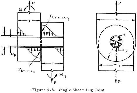
In Figure 9-6 a representative single-shear joint is shown, with centrally applied loads (P) in each lug, and bending moments (M and M1) that keep the system in equilibrium. (Assuming that there is no gap between the lugs, M + M1 = P(t + t1)/2). The individual values of M and M1 are determined from the loading of the lugs as modified by the deflection, if any, of the lugs, according to the principles of mechanics.
The strength analysis procedure outlined below applies to either lug. The joint strength is determined by the lowest of the margins of safety calculated for the different failure modes defined by Equations (9-23) through (9-27).
9.5.1 Lug Bearing Strength for Single Shear Joints Under Uniform Axial Loads
The bearing stress distribution between lug and bushing is assumed to be similar to the stress distribution that would be obtained in a rectangular cross section of width (D) and depth (t), subjected to a load (P) and moment (M). At ultimate load the maximum lug bearing stress (Fbr.max.L) is approximated by
where kbr.L is a plastic bearing coefficient for the lug material, and is assumed to be the same as the plastic bending coefficient (kb.L) for a rectangular section.
The allowable ultimate value of Fbr.max.L is either Fbru.L (Equations (9-1a) (9-1b)) or 1.304Fbry.L (Equations (9-2a) (9-2b)), whichever is lower.
9.5.2 Lug Net-Section Strength for Single Shear Joints Under Uniform Axial Load
At ultimate load the nominal value of the outer fiber tensile stress in the lug net-section is approximated by
where kb.L is the plastic bending coefficient for the lug net-section.
The allowable ultimate value of Ft.max is Fnu.L (Equation (9-4)) or 1.304Fny.L (Equation (9-5)), whichever is lower.
9.5.3 Bushing Strength for Single Shear Joints Under Uniform Axial Load
The bearing stress distribution between bushing and pin is assumed to be similar to that between the lug and bushing. At ultimate bushing load the maximum bushing bearing stress is approximated by
where kbr.L, the plastic bearing coefficient, is assumed the same as the plastic bending coefficient (kb.L) for a rectangular section.
The allowable ultimate value of Fbr.max.B is 1.304Fcy.B, where Fcy.B is the bushing material compressive yield strength.
9.5.4 Pin Shear Strength for Single Shear Joints Under Uniform Axial Load
The maximum value of pin shear can occur either within the lug or at the common shear face of the two lugs, depending upon the value of M/Pt. At the lug ultimate load the maximum pin shear stress (Fs.max.P) is approximated by
Equation (9-26a) defines the case where the maximum pin shear is obtained at the common shear face of the lugs, and Equation (9-26b) defines the case where the maximum pin shear occurs away from the shear face.
The allowable ultimate value of Fb.max.P is Fsu.P, the ultimate shear stress of the pin material.
9.5.5 Pin Bending Strength for Single Shear Joints Under Uniform Axial Load
The maximum pin bending moment can occur within the lug or at the common shear faces of the two lugs, depending on the value of M/Pt. At the lug ultimate load the maximum pin bending stress (Fb.max.P) is approximated by
where kbP is the plastic bending coefficient for the pin.
Equation (9-27a) defines the case where the maximum pin bending moment is obtained at the common shear face of the lugs, and Equation (9-27b) defines the case where the maximum pin bending moment occurs away from the shear face, where the pin shear is zero.
The allowable ultimate value of Fb.max.P is Ftu.P, the ultimate tensile stress of the pin material.
Need a Lug Calculator?
Try this lug calculator based on the methodology described here.
- Allows for axial, transverse, or oblique loading
- Performs calculations for lug strength, pin strength, and double shear joint strength
9.6 Example of Uniform Axially Loaded Lug Analysis
Determine the static strength of an axially loaded, double shear joint, such as shown in Section 9.4, with dimensions and material properties given in Table 9-1.
| Female Lugs, 1 | Male Lug, 2 | Bushings, 1 and 2 | Pin | |
|---|---|---|---|---|
| Material | 2024-T351 Plate | 7075-T651 Plate | Al. Bronze | 4130 Steel |
| Ftu | 64,000 psi (X-grain) |
77,000 psi (X-grain) |
110,000 psi | 125,000 psi |
| Fty | 40,000 psi (X-grain) |
66,000 psi (X-grain) |
60,000 psi | 103,000 psi |
| Fcy | 60,000 psi | |||
| Fsu | 82,000 psi | |||
| E | 10.5 x 10⁶ psi | 10.3 x 10⁶ | 29 x 106 psi | |
| ϵu | 0.12 | 0.06 | ||
| D or DP | D = 1.00 in | D = 1.00 in | DP = 0.75 in, D = 1.00 in |
DP = 0.75 in |
| e | 1.25 in | 1.5 in | ||
| a | 0.75 in | 1.00 in | ||
| w = WT | 2.50 in | 3.00 in | ||
| t | 0.50 in | 0.75 in | 0.50 and 0.75 in | |
| g | 0.10 in | |||
(1) Female Lugs and Bushings
Ftux = 64,000 psi; 1.304Ftyx = 1.304 × 40000 = 52,160 psi.
a) Lug Bearing Strength (Equations (9-2a) and (9-3b))
\( {e_1 \over D} = {1.25 \over 1.00} = 1.25 \); therefore K1 = 1.46 (from Figure 9-2)
Pbru.L.1 = 1.304 × 1.46 × 0.75 × 40000 × 1.00 × 0.50 = 28600 lbs.
b) Lug Net-Section Tension Strength (Equations (9-5) and (9-6b))
\( {D \over w_1} = {1.00 \over 2.50} = 0.40 \); \( {F_{ty} \over F_{tu}} = {40000 \over 64000} = 0.625 \);
\( {F_{tu} \over E \varepsilon_u} = {64000 \over 10.5 \times 10^6 \times 0.12} = 0.051 \); therefore, Kn.1 = 0.74 (by interpolation from Figure 9-4)
Pnu.L = 2 × 1.304 × 0.74 × 40000 × (2.5 - 1.0) × 0.5 = 57,898 lbs.
c) Lug Design Strength (Equation (9-7))
Pu.L.1 = Pbru.L.1 = 28600 lbs.
d) Bushing Bearing Strength (Equation (9-9))
Pu.B.1 = 1.304 × 60000 × 0.75 × 0.50 = 29300 lbs.
e) Combined Lug-Bushing Design Strength (Equation (9-10))
Pu.L.B.1 = Pu.L.1 = 28600 lbs.
(2) Male Lugs and Bushings
Ftux = 77,000 psi; 1.304Ftyx = 1.304 × 66000 = 86,100 psi.
a) Lug Bearing Strength (Equations (9-1b) and (9-3a))
\( {e_2 \over D} = {1.50 \over 1.00} = 1.50 \); therefore K2 = 1.33 (from Figure 9-2)
Pbru.L.2 = 1.33 × 77000 × 1.00 × 0.75 = 77000 lbs.
b) Lug Net-Section Tension Strength (Equations (9-4) and (9-6a))
\( {D \over w_2} = {1.00 \over 3.00} = 0.333 \); \( {F_{ty} \over F_{tu}} = {66000 \over 77000} = 0.857 \);
\( {F_{tu} \over E \varepsilon_u} = {77000 \over 10.3 \times 10^6 \times 0.06} = 0.125 \); therefore, Kn.2 = 0.87 (by interpolation from Figure 9-4)
Pnu.L = 1.304 × 87 × 66000 × (3.0 - 1.0) × 0.75 = 112,313 lbs.
c) Lug Design Strength (Equation (9-7))
Pu.L.2 = Pbru.L.2 = 77000 lbs.
d) Bushing Bearing Strength (Equation (9-9))
Pu.B.2 = 1.304 × 60000 × 0.75 × 0.75 = 44000 lbs.
e) Combined Lug-Bushing Design Strength (Equation (9-10))
Pu.L.B.2 = Pu.B.2 = 44000 lbs.
(3) Joint Analysis
a) Lug-Bushing Strength (Equation (9-11))
Pu.L.B = Pu.L.B.2 = 44000 lbs.
b) Pin Shear Strength (Equation (9-12))
Pus.P = 1.571 × (0.75)2 × 82000 = 72400 lbs.
c) Pin Bending Strength (Equation (9-15))
The pin ultimate bending load, assuming uniform bearing across the lugs, is
Since Pub.P is less than both Pu.L.B and Pus.P, the pin is a relatively weak pin which deflects sufficiently under load to shift the bearing loads toward the shear faces of the lugs. The new value of pin bending strength is, then,
(from Equation (9-16)) where
Therefore, Pub.P.max = 2 × 29000 × (0.754 - 0.10) = 37900 lbs.
The "balanced design" effective bearing widths are
\( b_{1.min} = {37900 \times 0.50 \over 2 \times 28600} = 0.331 ~\text{in} \) (from Equation(9-18a))
\( 2b_{2.min} = {37900 \times 0.75 \over 44000} = 0.646 ~\text{in} \) (from Equation(9-18b))
Therefore, the same value of Pub.P.max would be obtained if the thickness of each female lug was reduced to 0.331 inches and the thickness of the male lug reduced to 0.646 inches.
d) Joint Strength (Equation (9-19b))
The final allowable load for the joint, exclusive of the lug tangs, is
Pall = Pub.P.max = 37900 lbs.
(4) Lug Tang Analysis
|
$$ P_T = { 2 \times 64000 \times 2.50 \times 0.50 \over 1 + {3 \over 1.4} \times \left(0.1 - {0.331 \over 0.500}\right) } = 92700 ~\text{lbs} $$
|
(from Equation (9-22a)) |
or
PT = 77000 × 3.00 × 0.75 = 173300 lbs (from Equation (9-22b))
Therefore, the lug tangs are not critical and the allowable joint load remains at 37900 pounds.
Need a Lug Calculator?
Try this lug calculator based on the methodology described here.
- Allows for axial, transverse, or oblique loading
- Performs calculations for lug strength, pin strength, and double shear joint strength
9.7 Lug and Bushing Strength Under Transverse Load
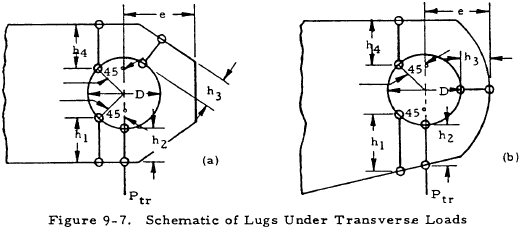
Transversely loaded lugs and bushings are checked in the same general manner as axially loaded lugs. The transversely loaded lug, however, is a more redundant structure than an axially loaded lug, and it has a more complicated failure mode. Figure 9-7 illustrates the different lug dimensions that are critical in determining the lug strength.
9.7.1 Lug Strength Under Transverse Load
The lug ultimate bearing stress (Fbru.L) is
where Ktru, the transverse ultimate load coefficient, is obtained from Figure 9-8 as a function of the "effective" edge distance (hav):
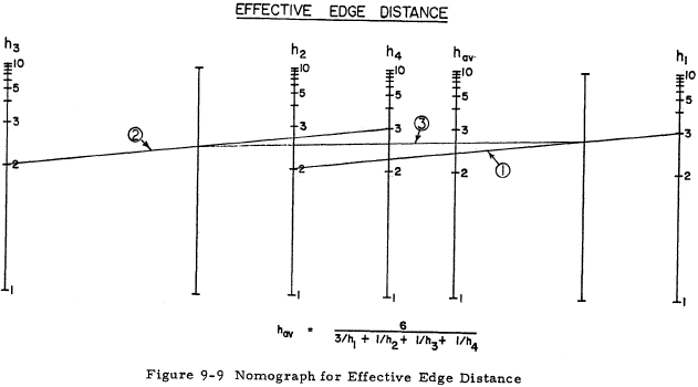
$$ h_{av} = { 6 \over 3/h_1 + 1/h_2 + 1/h_3 + 1/h_4 } $$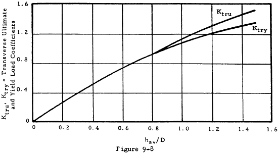
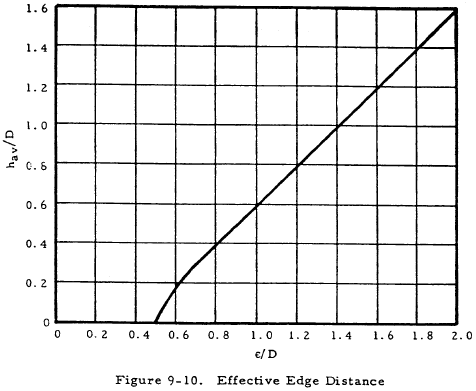
The effective edge distance can be found by using the nomograph in Figure 9-9. The nomograph is used by first connecting the h1 and h2 lines at the appropriate value of h1 and h2. The intersection with line A is noted. Next connect the h3 and h4 lines similarly, and note the B line intersection. Connecting the A and B line intersection gives the value of hav to be read at the intersection with the hav line. The different edge distances (h1, h2, h3, h4) indicate different critical regions in the lug, h1 being the most critical. The distance h3 is the smallest distance from the hole to the edge of the lug. If the lug is a concentric lug with parallel sides, hav/D can be obtained directly from Figure 9-10 for any value of e/D. In concentric lugs, h1 = h4 and h2 = h3.
The lug yield bearing stress (Fbry.L) is
where Ktry, the transverse yield load coefficient, is obtained from Figure 9-8.
The allowable lug transverse ultimate load (Ptru.L) is
where Fbru.L and Fbry.L are obtained from Equations (9-28) and (9-29).
If the lug is not of constant thickness, then Aav/Abr is substituted for hav/D on the horizontal scale of the graph in Figure 9-8, where Abr is the lug bearing area, and
$$ A_{av} = { 6 \over 3/A_1 + 1/A_2 + 1/A_3 + 1/A_4 } $$A1, A2, A3, and A4 are the areas of the sections defined by h1, h2, h3, and h4, respectively.
The values of Ktru and Ktry corresponding to Aav/Abr are then obtained from the graph in Figure 9-8 and the allowable bearing stresses are obtained as before from Equations (9-28) and (9-29).
9.7.2 Bushing Strength Under Transverse Load
The allowable bearing stress on the bushing is the same as that for the bushing in an axially loaded lug and is given by Equation (9-8). The allowable bushing ultimate load (Ptru.B) is equal to Pu.B (Equation (9-9)).
9.8 Double Shear Joints Under Transverse Load
The strength calculations needed for double shear joint strength analysis are basically the same as those needed for axially loaded. Equations (9-11) through (9-19) can be used; however, the maximum lug bearing stresses at ultimate and yield loads must not exceed those given by Equations (9-28) and (9-29).
9.9 Single Shear Joints Under Transverse Load
The previous discussion on double shear joint applies to single shear joint strength analysis except the equations to be used are now Equations (9-23) through (9-27).
9.10 Lug and Bushing Strength Under Oblique Load
The analysis procedures used to check the strength of axially loaded lugs and of transversely loaded lugs are combined to analyze obliquely loaded lugs such as the one shown in Figure 9-11. These procedures apply only if α does not exceed 90°.
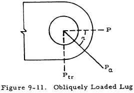
9.10.1 Lug Strength Under Oblique Load
The obliquely applied load (Pα) is resolved into an axial component (P = Pα cosα) and a transverse component (Ptr = Pα sinα). The allowable ultimate value of Pα is Pα.L and its axial and transverse components satisfy the following equation:
where Pu.L is the strength of an axially loaded lug (Equation (9-7)) and Ptru.L is the strength of a transversely loaded lug (Equations (9-30a), (9-30b)). The allowable load curve defined by Equation (9-31) is plotted on the graph in Figure 9-12.
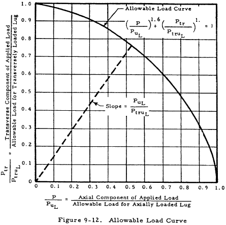
For any given value of α the allowable load (Pα.L) for a lug can be determined from the graph shown in Figure 9-12 by drawing a line from the origin with a slope equal to (Pu.L/Ptru.L). The intersection of this line with the allowable load curve (point 1 on the graph) indicates the allowable values of P/PL and Ptr/Ptru.L, from which the axial and transverse components, P and Ptr of the allowable load can be readily obtained.
9.10.2 Bushing Strength Under Oblique Load
The bushing strength calculations are identical to those for axial loading (Equations (9-8) and (9-9)).
9.11 Double Shear Joints Under Oblique Load
The strength calculations are basically the same as those for an axially loaded joint except that the maximum lug bearing stress at ultimate load must not exceed Pα.L/Dt, where Pα.L is defined by Equation (9-31). Use Equations (9-11) through (9-19)).
9.12 Single Shear Joints Under Oblique Load
The previous discussion on double shear joints applies to single shear joint strength analysis except the equations to be used are now Equations (9-23) through (9-27).
9.13 Multiple Shear and Single Shear Connections
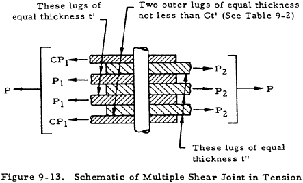
Lug-pin combinations having the geometry indicated in Figure 9-13 should be analyzed according to the following criteria:
- The load carried by each lug should be determined by distributing the total applied load P among the lugs as indicated in Figure 9-13, b being obtained in Table 9-2. This distribution is based on the assumption of plastic behavior (at ultimate load) of the lugs and elastic bending of the pin, and gives approximately zero bending deflection of the pin.
- The maximum shear load on the pin is given in Table 9-2.
- The maximum bending moment in the pin is given by the formulae
| $$ M = {P_1 b \over 2} $$ | where b is given in Table 9-2. |
| Total number of lugs including both sides |
C | Pin Shear | b |
|---|---|---|---|
| 5 | 0.35 | 0.50P1 | $$ 0.28 ~{ t' + t'' \over 2 } $$ |
| 7 | 0.40 | 0.53P1 | $$ 0.33 ~{ t' + t'' \over 2 } $$ |
| 9 | 0.43 | 0.54P1 | $$ 0.37 ~{ t' + t'' \over 2 } $$ |
| 11 | 0.44 | 0.54P1 | $$ 0.39 ~{ t' + t'' \over 2 } $$ |
| ∞ | 0.50 | 0.50P1 | $$ 0.50 ~{ t' + t'' \over 2 } $$ |
Need a Lug Calculator?
Try this lug calculator based on the methodology described here.
- Allows for axial, transverse, or oblique loading
- Performs calculations for lug strength, pin strength, and double shear joint strength
9.14 Axially Loaded Lug Design
This section presents procedures for the optimized design of lugs, bushings and pin in a symmetrical, double-shear joint, such as shown in Figure 9-5, subjected to a static axial load (P). One design procedure applies to the case where the pin is critical in shear, the other to the case where the pin is critical in bending. A method is given to help determine which mode of pin failure is more likely, so that the appropriate design procedure will be used.
Portions of the design procedures may be useful in obtaining efficient designs for joints other than symmetrical, double-shear joints.
9.14.1 Axial Lug Design for Pin Failure
An indication of whether the pin in an optimized joint design is more likely to fail in shear or in bending can be obtained from the value of R (Equation (9-32)). If R is less than 1.0, the pin is likely to fail in shear and the design procedure for joints with pins critical in shear should be used to get an optimized design. If R is greater than 1.0, the pin is likely to be critical in bending and the design procedures for joints with pins critical in bending should be used.
where Fsu.P and Ftu.P are the ultimate shear and ultimate tension stresses for the pin material, kb.P is the plastic bending coefficient for the pin, and Fbr.all.1 and Fbr.all.2 are allowable bearing stresses in the female and male lugs. The value of Fbr.all.1 can be approximated by the lowest of the following three values:
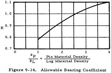
K Ftux.1 D/DP; 1.304K Ftyx.1 D/DP; 1.304Fcy.B.1
where Ftux.1 and Ftyx.1 are the cross-grain tensile ultimate and tensile yield stress for female lugs, Fcy.B.1 is the compressive yield stress of the bushings in the female lugs, and K is obtained from Figure 9-14. Assume D = DP if a better estimate cannot be made. Fbr.all.2 is approximated in a similar manner.
9.14.1.1 Axial Lug Design for Pin Failure in the Shearing Mode
Pin and Bushing Diameter
The minimum allowable diameter for a pin in double shear is
The outside diameter of the bushing is D = DP + 2tB where tB is the bushing wall thickness.
Edge Distance Ratio (e/D)
The value of e/D that will minimize the combined lug and pin weight is obtained from Figure 9-15(a) for the case where lug bearing failure and pin shear failure occur simultaneously. The lug is assumed not critical in net tension, and the bushing is assumed not critical in bearing.
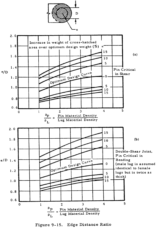
The curves in Figure 9-15 apply specifically to concentric lugs (a = e - D/2, and w = 2e), but they can be used for reasonably similar lugs.
Allowable Loads
The allowable loads for the different failure modes (lug bearing failure, lug net-tension failure, and bushing failure) are determined from Equations (9-3), (9-6), and (9-9) in terms of the (unknown) lug thickness. The lowest of these loads is critical.
Lug Thicknesses
The required male and female lug thicknesses are determined by equating the applied load in each lug to the critical failure load for the lug.
Pin Bending
To prevent bending failure of the pin before lug or bushing failure occurs in a uniformly loaded symmetrical double-shear joint, the required pin diameter is
where kb.P is the plastic bending coefficient for the pin. If the value of DP from Equation (9-34) is greater than that from Equation (9-33), the joint must be redesigned because the pin is critical in bending.
Reduced Edge Distance
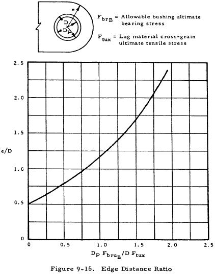
If the allowable bushing load (Equation (9-9)) is less than the allowable lug load (Equation (9-3)), a reduced value of e, obtained by using the curve shown in Figure 9-16 for optimum e/D, will give a lighter joint in which lug bearing failure and bushing bearing failure will occur simultaneously. The previously calculated pin diameter and lug thicknesses are unchanged.
Reduced Lug Width
If the lug net-tension strength (Equation (9-6)) exceeds the bearing strength (Equation (9-3)), the net-section width can be reduced by the ratio of the bearing strength to the net-tension strength.
9.14.1.2 Axial Lug Design for Pin Failure in the Bending Mode
Pin and Bushing Diameters (First Approximation)
A first approximation to the optimum pin diameter is shown in Equation (9-35).
where Ft.all.1 is either Ftux.1 or 1.304Ftyx.1 whichever is smaller; and Ft.all.2 is either Ftux.2 or 1.304Ftyx.2 whichever is smaller. This approximation becomes more accurate when there are no bushings and when there is no gap between lugs.
The first approximation to the outside diameter of the bushing is D = DP + 2tB.
Edge Distance Ratio (e/D)
The value of e/D that will minimize the combined lug and pin weight is obtained from Figure 9-15(b) for the case of symmetrical double-shear joints in which lug bearing failure and pin bending failure occur simultaneously. The lug is assumed not critical in tension and the bushing is assumed not critical in bearing.
The curves apply specifically to concentric lugs (a = e - D/2, and w = 2e), but can be used for reasonably similar lugs.
Allowable Loads (First Approximation)
The allowable loads for the different failure modes (lug bearing failure, lug net-tension failure, and bushing failure) are determined from Equations (9-3), (9-6), and (9-9), in terms of the (unknown) lug thickness. The lowest of these loads is critical.
Lug Thicknesses (First Approximation)
The first approximation to the required male and female lug thicknesses are determined by equating the applied load in each lug to the lowest allowable load for the lug.
Pin Diameter (Second Approximation)
The second approximation to the pin diameter is obtained by substituting the first approximation lug thicknesses into Equation (9-34).
Final Pin and Bushing Diameters and Lug Thicknesses
The final optimum pin diameter is very closely approximated by
DP.opt = 1/3 DP (Equation (9-35)) + 2/3 DP (Equation (9-34))
An average value, however, is generally sufficient. If the final optimum value is not a standard pin diameter, choose the next larger standard pin and bushing.
The final lug thicknesses corresponding to the standard pin and bushing are then determined.
Pin Shear
The pin is checked for shear strength (Equation (9-33)).
Reduced Edge Distance
If the bushing bearing strength (Equation (9-9)) is less than the lug bearing strength (Equation (9-3)), a reduced value of e/D, obtained from the curve in Figure 9-16, will give a lighter joint. The pin diameter and lug thicknesses are unchanged.
Reduced Lug Width
If the lug net-tension strength (Equation (9-6)) exceeds the lug bearing strength (Equation (9-3)), the net-section width can be reduced by the ratio of the bearing strength to the net-tension strength.
9.14.1.3 Example of Axially Loaded Lug Design
Using the same materials for the lug, bushing and pin as mentioned in Section 9.6, and assuming the same allowable static load of 37900 pounds, a symmetrical double-shear joint will be designed to carry this load. A 0.10-inch gap is again assumed between the lugs. The bushing wall thickness is assumed to be 1/8 inch.
The lug will first be assumed to be concentric (a = e - D/2, and w = 2e) but the final minimum weight design will not necessarily be concentric.
Pin Failure Mode (Equation (9-32))
The pin is first checked to determine whether it will be critical in shear or bending, using Equation (9-32). Assuming D = DP as a first approximation, determine Fbr.all.1 and Fbr.all.2, using the graph in Figure 9-14 to determine K.
KFtux.1 = 1.02 × 64000 = 65300 psi; 1.304KFtyx.1 = 1.304 × 1.02 × 40000 = 53100 psi
1.304Fcy.B.1 = 1.304 × 60000 = 78200 psi; therefore, Fbr.all.1 = 53100 psi
KFtux.2 = 1.02 × 77000 = 78500 psi; 1.304KFtyx.2 = 1.304 × 1.02 × 66000 = 53100 psi
1.304Fcy.B.2 = 1.304 × 60000 = 78200 psi; therefore, Fbr.all.2 = 78200 psi
Therefore,
|
$$ R = { \pi \times 82000 \over 1.56 \times 125000 } \times \left( {82000 \over 53100} + {82000 \over 78200} \right) = 3.4 $$
|
(Equation (9-32)) |
Therefore, the design procedure for pins critical in bending applies.
Pin and Bushing Diameters - First Approximation (Equation (9-35))
D = 0.741 + 2 × 0.125 = 0.991 in
Edge Distance Ration (e/D)
The optimum value of e/D for both male and female lugs is 1.24 (Figure 9-15 (b)). Therefore a/D is 0.74 and w/D is 2.48 for a concentric lug (therefore, w = 2.46 in).
Allowable Loads - Female Lugs and Bushings (First Approximation)
(a) Lug Bearing Strength (Equations (9-2a) and (9-36))
Pbru.L.1 = 1.304 × 1.46 × 0.74 × 40000 × 0.991t1 = 55900t1 lbs
where K = 1.46 is obtained from Figure 9-2 for e/D = 1.24
(b) Lug Net-Section Tension Strength (Equations (9-5) and (9-6b))
Kn.1 = 0.74 (obtained by interpolation from the graphs shown in Figure 9-4) for D/w = 0.403; Fty/Ftu = 0.625; Ftu/Eϵu = 0.051
Pnu.L.1 = 1.304 × 40000 × (2.46 − 0.991) t1 = 56600 t1 lbs
(c) Bushing Bearing Strength (Equation (9-9))
Pu.B.1 = 1.304 × 60000 × 0.741 t1 = 58000 t1 lbs
Allowable Loads - Male Lug and Bushing (First Approximation)
(a) Lug Bearing Strength (Equations (9-la) and (9-3a))
Pbru.L.2 = 1.46 × 0.74 × 77000 × 0.991 t2 = 82500 t2 lbs
(b) Lug Net-Section Tension Strength (Equations (9-4) and (9-6a))
Kn.2 = 0.88 (obtained by interpolation from the graphs shown in Figure 9-4) for D/w2 = 0.403; Fty/Ftu = 0.857; Ftu/Eϵu = 0.125
Pnu.L.2 = 0.88 × 77000 × (2.46 − 0.991) t2 = 99500 t2 lbs
(c) Bushing Bearing Strength (Equation (9-9))
Pu.B.2 = 1.304 × 60000 × 0.741 t2 = 58000 t2 lbs
Lug Thicknesses (First Approximation)
\( t_1 = {37900 \over 2 \times 55900} \) = 0.339 in; \( t_2 = {37900 \over 58000} \) = 0.654 in
Pin Diameter - Second Approximation (Equation (9-34))
D = 0.7555 + 2 × 0.125 = 1.0005 in
Final Pin and Bushing Diameter (Equation (9-36))
DP.opt = 0.741/2 + 0.755/2 = 0.748 in (Use 0.750 inch pin)
D = 0.750 + 2 × 0.125 = 1.000 in
Pin Shear (Equation (9-33))
$$ D_P = 0.798 \sqrt{ 37900 \over 82000 } = 0.541 ~\text{in} $$Therefore, the pin is not critical in shear.
Final Lug Thicknesses
t1 = 0.339 × 0.991/1.000 = 0.336 in
t2 = 0.654 × 0.741/0.750 = 0.646 in
Reduced Edge Distance
The lug tension strength (Equation (9-3)) exceeds the bushing strength (Equation (9-9)) for the male lug. Therefore, a reduced e/D can be obtained for the male lug shown in Figure 9-16.
Therefore, e/D = 0.97 (male lug)
Reduced Lug Width
The lug net-section tension strength (Equation (9-6)) exceeds the bearing strength (Equation (9-3)) for both the male and female lugs. Therefore, the widths can be reduced as follows:
Final Dimensions
DP = 0.750 in; D = 1.000 in;
t1 = 0.336 in; e1 = 1.24 in; w1 = 2.46 in;
t2 = 0.646 in; e2 = 0.97 in; w2 = 2.23 in;
Since w2 is larger than 2e2, the final male lug is not concentric.
Need a Lug Calculator?
Try this lug calculator based on the methodology described here.
- Allows for axial, transverse, or oblique loading
- Performs calculations for lug strength, pin strength, and double shear joint strength
9.15 Analysis of Lugs with Less Than 5 PCT Elongation
The procedures given through Section 9-14 for determining the static strength of lugs apply to lugs made from materials which have ultimate elongations, ϵu, of at least 5% in all directions in the plane of the lug. This section describes procedures for calculating reductions in strength for lugs made from materials which do not meet the elongation requirement. In addition to using these procedures, special consideration must be given to possible further loss in strength resulting from material defects when the short transverse gain direction of the lug material is in the plane of the lug.
The analysis procedures for lugs made from materials without defects but with less than 5% elongation are as follows:
9.15.1 Bearing Strength of Axially Loaded Lugs with Less Than 5 PCT Elongation
- Determine Fty/Ftu and ϵy/ϵu, using values of Fty, Ftu, ϵy and ϵu that correspond to the minimum value of ϵu in the plane of the lug.
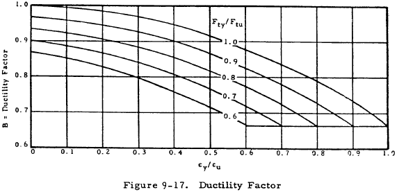
- Determine the value of B, the ductility factor, from the graph shown in Figure 9-17.
- Determine a second value of B (denoted by B0.05) for the same values of Fty, Ftu, and ϵy as before, but with ϵu = 0.05.
- Multiply the bearing stress and bearing load allowables given by Equations (9-1a) through (9-3b) by B/B0.05 to obtain the corrected allowables.
9.15.2 Net-Section Strength of Axially Loaded Lugs with Less Than 5 PCT Elongation
The procedure for determining net-section allowables is the same for all values of ϵu. The graphs in Figure 9-4 are used to obtain a value of Kn which is susbstituted in Equations (9-4) and (9-5). If the grain direction of the material is known, the values of Fty, Ftu, and ϵu used in entering the graphs should correspond to the grain direction parallel to the load. Otherwise, use values corresponding to the minimum value of ϵu in the plane of the lug.
9.15.3 Strength of Lug Tangs in Axially Loaded Lugs with Less Than 5 PCT Elongation
The plastic bending coefficient for a rectangular cross section can be approximated by kb.L = 1.5B, where B is obtained from Figure 9-17, in which y and u are the yield and ultimate strains of the lug tang material in the direction of loading. The maximum allowable value of kb.L for a rectangle is 1.4.
9.15.4 Lug-Bushing Strength in Axially-Loaded Single-Shear Joint with Less Than 5 PCT Elongation
The values of kbr.L and kb.L for rectangular cross sections are approximated by 1.5B, where B is determined from the graph as described in Figure 9-17. The maximum allowable values of kbr.L and kb.L are 1.4.
9.15.5 Bearing Strength of Transversely Loaded Lugs with Less Than 5% Elongation
(Equations (9-28) through (9-30b) in Section 9.7.1)
The same procedure as that for the bearing strength of axially loaded lugs is used.
- Determine B and B0.05 as described for axially loaded lugs, where B corresponds to the minimum value of ϵu in the plane of the lug.
- Multiply the bearing stress and bearing load allowables given by Equations (9-28) through (9-30b) by B/B0.05 to obtain the corrected allowables.
9.16 Stresses Due to Press Fit Bushings
Pressure between a lug and bushing assembly having negative clearance can be determined from consideration of the radial displacements. After assembly, the increase in inner radius of the ring (lug) plus the decrease in outer radius of the bushing equals the difference between the radii of the bushing and ring before assembly:
where
δ = Difference between outer radius of bushing and inner radius of the ring.
u = Radial displacement, positive away from the axis of ring or bushing.
Radial displacement at the inner surface of a ring subjected to internal pressure p is
Radial displacement at the outer surface of a bushing subjected to external pressure p is
where
| A = Inner radius of bushing | D = Inner radius of ring (lug) |
| B = Outer radius of bushing | E = Modulus of elasticity |
| C = Outer radius of ring (lug) | μ = Poisson's ratio |
Substitute Equations (9-37) and (9-38) into Equation (9-36) and solve for p:
Maximum radial and tangential stresses for a ring subjected to internal pressure occur at the inner surface of the ring (lug).
| $$ F_r = -p $$ | $$ F_t = p \left[{ C^2 + D^2 \over C^2 - D^2 }\right] $$ |
Positive sign indicates tension. The maximum shear stress at this point is
$$ F_s = {F_t - F_r \over 2} $$The maximum radial stress for a bushing subjected to external pressure occurs at the outer surface of the bushing is
$$ F_r = -p $$The maximum tangential stress for a bushing subjected to external pressure occurs at the inner surface of the bushing is
$$ F_t = { -2_{PB}^2 \over B^2 = A^2 } $$The allowable press fit stress may be based on:
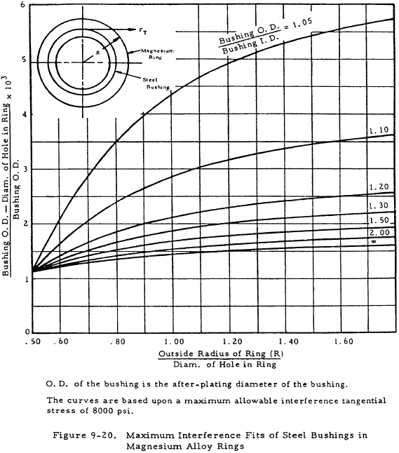
- Stress Corrosion. The maximum allowable press fit stress in magnesium alloys should not exceed 8000 psi. For all alumimun alloys the maximum press fit stress should not exceed 0.50Fty.
- Static Fatigue. Static fatigue is the brittle fracture of metals under sustained loading, and in steel may result from several different phenomena, the most familiar of which is hydrogen embrittlement. Steel parts heat treated above 200 ksi, which by nature of their function or other considerations are exposed to hydrogen embrittlement, should be designed to an allowable press fit stress of 25% Ftu.
- Ultimate Strength. Ultimate strength cannot be exceeded, but is not usually critical in a press fit application.
- Fatigue Life. The hoop tension stresses resulting from the press fit of a bushing in a lug will reduce the stress range for oscillating loads, thereby improving fatigue life.
The presence of hard brittle coatings in holes that contain a press fit bushing or bearing can cause premature failure by cracking of the coating or by high press fit stresses caused by build-up of coating. Therefore, Hardcoat or HAE coatings should not be used in holes that will subsequently contain a press fit bushing or bearing.
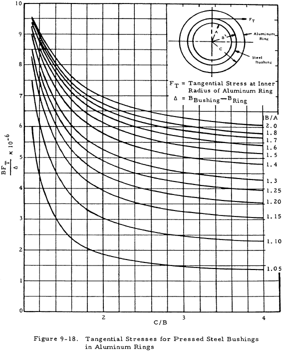
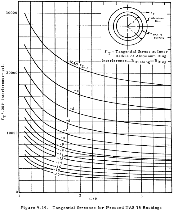
Figures 9-18 and 9-19 permit determining the tangential stress, FT, for bushings pressed into aluminum rings. Figure 9-18 presents data for general steel bushings, and Figure 9-19 presents data for the NAS 75 class bushings. Figure 9-20 gives limits for maximum interference fits for steel bushings in magnesium alloy rings.
