Frames and Rings
This page provides the sections on the analysis of frames and rings from the "Stress Analysis Manual," Air Force Flight Dynamics Laboratory, October 1986.
Other related chapters from the Air Force "Stress Analysis Manual" can be seen to the right.
- Frames and Rings
- Formulas for Simple Frames
- Circular Rings & Arches
5.1 Introduction to Frames and Rings
Frames and rings are statically indeterminate structures. A frame is such a structure composed of prismatic elements joined rigidly at points of intersection while the element or elements of a ring are curved.
Section 5.3 treats the method of moment distribution for solving frame problems. Section 5.5 treats symmetrical rectangular frames under vertical loading. Section 5.7 gives formulas for simple rectangular, trapezoidal, and triangular frames under various simple loadings. Circular rings and arches are treated in Section 5.9.
5.2 Nomenclature for Frames and Rings
| A | = | cross-sectional area |
| Am | = | area under the moment diagram of a simply supported beam |
| a | = | linear dimension |
| b | = | linear dimension |
| c | = | linear dimension |
| D | = | diameter |
| DF | = | distribution factor |
| d | = | linear dimension |
| d | = | distance to centroid of load |
| E | = | modulus of elasticity |
| FEM | = | fixed end moment |
| H | = | horizontal reaction |
| h | = | height |
| I | = | moment of inertia |
| K | = | stiffness factor =I/L |
| L | = | length |
| M | = | moment |
| P | = | applied concentrated load |
| R | = | radius |
| s | = | length of upright of a trapezoidal frame |
| T | = | tensile force |
| V | = | shear force |
| V | = | vertical reaction |
| W | = | applied concentrated load |
| w | = | applied distributed load |
| x, y, z | = | rectangular coordinates |
| x | = | angular distance from the bottom of a circular ring |
| Δ | = | increment or difference |
| β | = | angle |
| θ | = | rotation of the tangent to the elastic curve of a moment at its end |
| ϕ | = | angle |
| ψ | = | rotation of the chord joining the ends of the elastic curve of a member |
| (Ωo)A | = | moment of the Mo portion of the moment diagram of a member (Figure 5-1) about point A |
5.3 Solution of Frames by the Method of Moment Distribution
This section treats frames composed of prismatic members whose joints do not translate. All members of such frames are assumed to be elastic.
The five basic factors involved in the method of moment-distribution are: fixed-end moments, stiffness factors, distribution factors, distributed moments, and carry-over moments.
The fixed-end moments are obtained by the use of the following equations:
and
where:
| MAB | = | the moment acting on the end of member AB labeled as A |
| MBA | = | the moment acting on the end of member AB labeled as B |
| E | = | the modulus of elasticity of member AB |
| I | = | the moment of inertia of member AB |
| L | = | length of member AB |
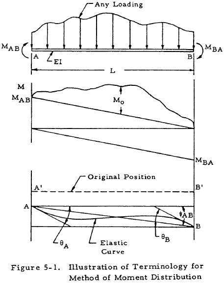
| θ | = | rotation of the tangent to the elastic curve at the end of the member |
| ψ | = | rotation of the chord joining the ends of the elastic curve referred to the original direction of the member |
| (Ωo)A | = | static moment about a vertical axis through A of the area under the Mo portion of the bending moment diagram |
| (Ωo)B | = | static moment about an axis through B |
This terminology is illustrated in Figure 5-1.
If both ends of the member are completely fixed against rotation and translation, the member is called a fixed-end beam and θA, θB, and ψAB are all equal to zero. Thus, the last terms of Equations (5-1) and (5-2) are equal to the so-called "fixed-end moments." Denoting the fixed-end moments as FEM,
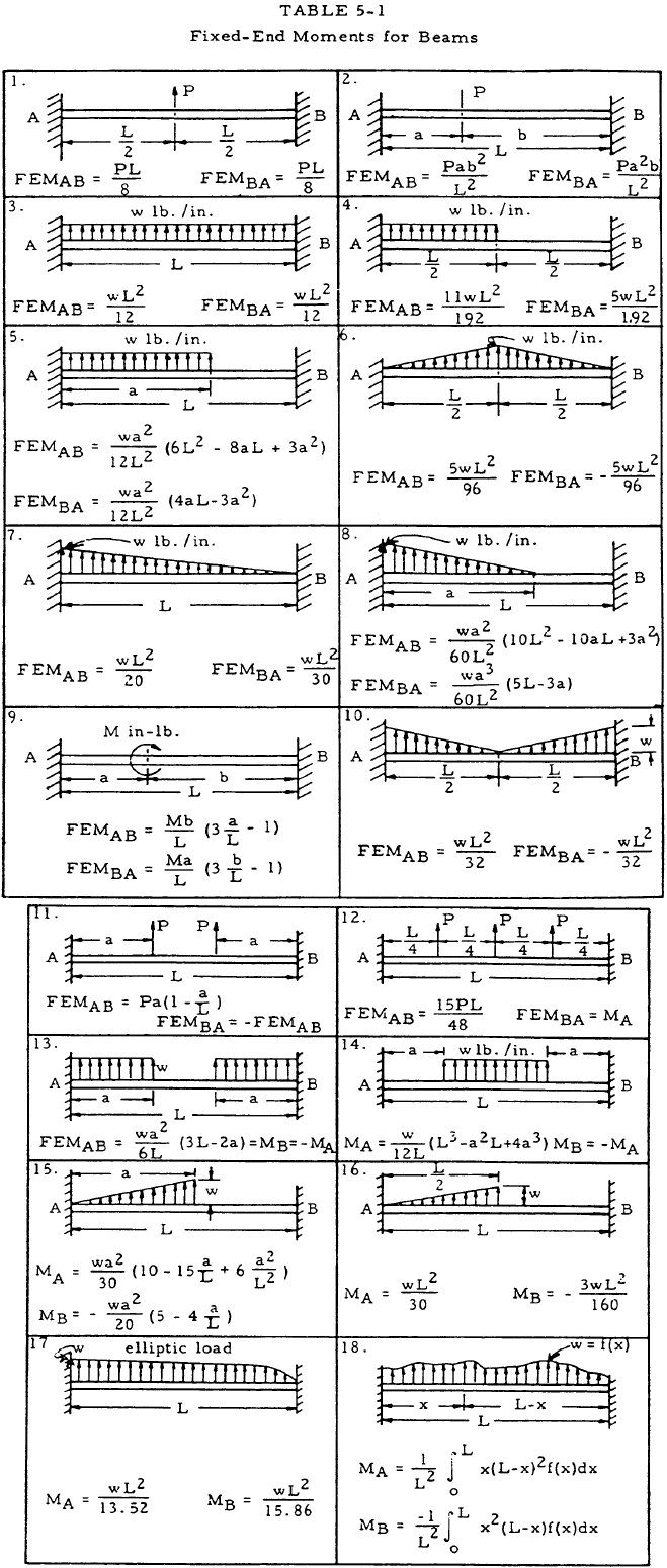
Fixed-end moments for various simple types of loading were calculated and are given in Table 5-1.
Equations (5-1) and (5-2) may be represented by one general equation by calling the near end of a member "N" and the far end "F." The stiffness factor of member NF is given by
Thus, the fundamental slope deflection equation becomes
The conditions to be met at a joint of a frame are: (1) the angle of rotation be the same for the ends of all members that are rigidly connected at a joint, and (2) the algebraic sum of all moments be zero. The method of moment distribution renders to zero by iteration any unbalance in moment at a joint to satisfy the second condition.
A distribution factor which represents the relative portion of the unbalanced moment which is reacted by a member is used to distribute the unbalanced moment. This distribution factor is given for any member bm by
where the summation includes all members meeting at joint b.
The distributed moment in any bar bm is then
This equation may be interpreted as follows:
The distributed moment developed at the "b" end of member bm as joint b is unlocked and allowed to rotate under an unbalanced moment, M, is equal to the distribution factor DFbm times the unbalanced moment, M, with the sign reversed.
The "carry-over" moment is obtained by applying Equation (5-6) and considering θm = ψbm = 0 as in Figure 5-2. The "carry-over" moment is equal to half of its corresponding distributed moment and has the same sign.
and
Thus,

The sign convention for moments in the method of moment distribution is to consider moments acting clockwise on the ends of a member as positive. This convention is illustrated in Figure 5-3.

The following procedure is for the process of moment distribution analysis:
- Compute the stiffness factor, K, for each member and record.
- Compute the distribution factor, DF, of each member at each joint and record.
- Compute the fixed-end moments, FEM, for each loaded span and record.
- Balance the moments at a joint by multiplying the unbalanced moment by the distribution factor, changing sign, and recording the balancing moment below the fixed-end moment. The unbalanced moment is the sum of the fixed-end moments of a joint.
- Draw a horizontal line below the balancing moment. The algebraic sum of all moments at any joint above the horizontal line must be zero.
- Record the carry-over moment at the opposite ends of the member. Carry-over moments have the same sign as the corresponding balancing moments and are half their magnitude.
- Move to a new joint and repeat the process for the balance and carry-over of moments for as many cycles as desired to meet the required accuracy of the problem. The unbalanced moment for each cycle will be the algebraic sum of the moments at the joint recorded below the last horizontal line.
- Obtain the final moment at the end of each member as the algebraic sum of all moments tabulated at this point. The total of the final moments for all members at any joint must be zero.
- Reactions, vertical shear, and bending moments of the member may be found through statics by utilizing the above mentioned final moments.
The use of this procedure is illustrated in Section 5.4. It should be noted that simpler methods may be found for the solution of rectangular, trapezoidal, and triangular frames in Sections 5.5 and 5.7.
We have a number of structural calculators to choose from. Here are just a few:
5.4 Sample Problem - Solution of Frames by the Method of Moment Distribution
Given: The frame shown in Figure 5-4.
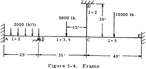
Find: The end moments and draw the moment diagrams for this frame.
Solution:
(1) From Equation (5-5), the stiffness factors of the members are:
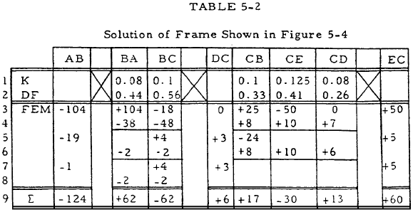
$$ K_{BA} = { I_{BA} \over L_{BA} } = { 2 \over 25 } = 0.08 $$ $$ K_{BC} = { I_{BC} \over L_{BC} } = { 3.5 \over 35 } = 0.1 $$ $$ K_{CE} = { I_{CE} \over L_{CE} } = { 5 \over 40 } = 0.125 $$ $$ K_{CD} = { I_{CD} \over L_{CD} } = { 2 \over 25 } = 0.08 $$These are recorded in line 1 of Table 5-2.
(2) From Equation (5-6), the distribution factors of the members are:
$$ DF_{BA} = { K_{BA} \over K_{BA} + K_{BC} } = { 0.08 \over 0.08 + 0.1 } = 0.44 $$ $$ DF_{BC} = { K_{BC} \over K_{BA} + K_{BC} } = { 0.1 \over 0.08 + 0.1 } = 0.56 $$These distribution factors are recorded in line 2 of Table 5-2.
(3) From Table 5-1, case 3,
From Table 5-1, case 2,
From Table 5-1, case 1,
Since member CD is unloaded,
$$ FEM_{CD} = FEM_{DC} = 0 $$These results are summarized in line 3 of Table 5-2.
(4) The unbalanced moment at joint B is
$$ \sum FEM = 104 - 18 = 86 $$The moments at joint B may be balanced by multiplying this unbalanced moment by the distribution factor and changing sign. The result is recorded in line 4 of Table 5-2.
(5) A horizontal line may be drawn below the balancing moments in line 4 of Table 5-2. The algebraic sum of all the moments at this joint above this line is zero; that is,
$$ -104 + 18 + 38 + 48 = 0 $$(6) The carry-over moments at the opposite ends of the members are recorded as shown in line 5 of Table 5-2. These carry-over moments have the same sign as the corresponding balancing moments and are half their magnitude.
(7) Steps 4, 5, and 6 may be repeated for joint C to obtain the rest of the values shown in rows 4 and 5 of Table 5-2. The process for the balance and carry-over of moments may be repeated for as many cycles as desired to meet the required accuracy of the problem. The unbalanced moment for each cycle will be the algebraic sum of the moments at the joint recorded below the last horizontal line. This process is shown on lines 6, 7, and 8 of Table 5-2.
(8) The final moment at the end of each member may be obtained as the algebraic sum of all moments tabulated in the first seven lines of Table 5-2. This summation is shown in line 9 of Table 5-2.
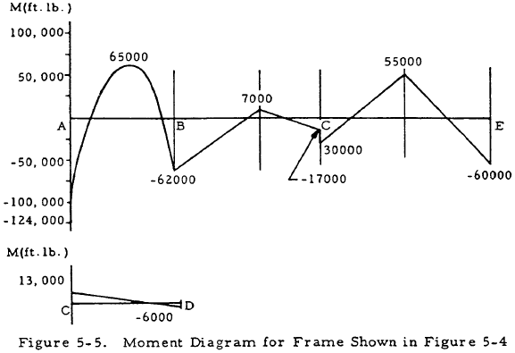
Now that the moments in each of the members at the joints are known, the moment diagrams may be drawn for the members with the aid of the equations of static equilibrium. These moment diagrams are shown in Figure 5-5.
We have a number of structural calculators to choose from. Here are just a few:
5.5 Rectangular Frames
This section considers symmetrical rectangular frames that are either pinned or fixed at the ends of both of their uprights.
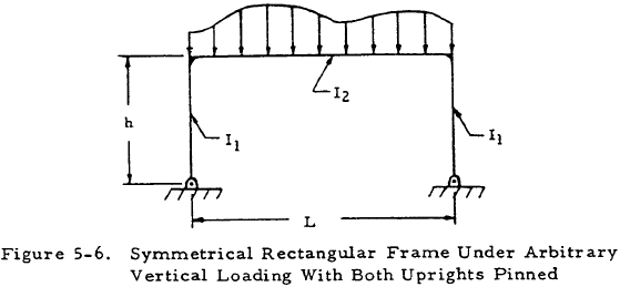
Figure 5-6 shows a symmetrical rectangular frame both of whose uprights are pinned under some arbitrary vertical loading. Such a frame is statically indeterminate and an equation, in addition to those of statics, must be applied to determine the moments in its members.
The free-body diagram of this frame may be drawn as shown in Figure 5-7.
The horizontal reaction is given by
where
and Am is the area under the moment diagram for a simply supported beam under the same loading as the horizontal member of the given frame. Once the horizontal reactions have been found by Equation (5-11), the moment diagrams of the frame members may be found by the equations of statics.
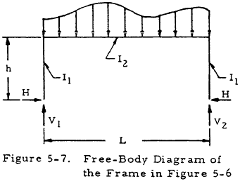
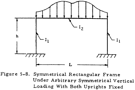
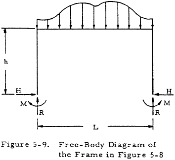
Figure 5-8 shows a symmetrical rectangular frame both of whose uprights are fixed under some arbitrary symmetrical vertical loading. Such a frame is statically indeterminate with two indeterminates, and two equations, in addition to those of statics, must be applied to determine the moments in its members.
The free-body diagram of this frame may be drawn as shown in Figure 5-9. The horizontal reaction is given by
where
and Am is the area under the moment diagram for a simply supported beam under the same loading as the horizontal member of the given frame. The reaction moment on the ends of the uprights is given by
where K and Am are defined as before. Once the horizontal reactions and reaction moments have been found by Equations (5-11) and (5-13), the moment diagrams of the frame members may be found by the equations of statics. This procedure is illustrated in Section 5.6.
It should be noted that solutions for rectangular frames under various simple loadings are given in tabular form in Section 5.7. The use of this material, when applicable, is much simpler than using the material in this section.
5.6 Sample Problem - Rectangular Frames
Given: The symmetrically loaded frame shown in Figure 5-10.
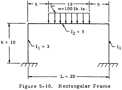
Find: The bending moment diagram.
Solution:
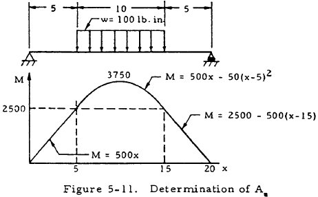
$$ K = { I_2 ~h \over I_1 ~L } = { 5(10) \over 3(20) } = 0.834 $$To find Am, consider the simply supported beam shown in Figure 5-11 and draw its moment diagram. The area under this moment diagram may be found to be
$$ A_m = 45800 ~\text{in.}^2 ~\text{lb.} $$Substituting this and K into Equations (5-13) and (5-15) gives
and
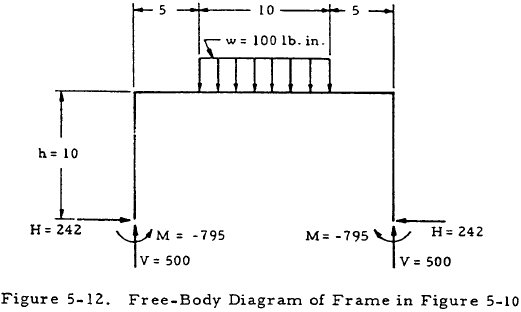
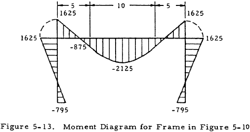
A free-body diagram may now be drawn for the frame and the vertical reactions computed as shown in Figure 5-12. The equations of statics may now be applied to sections of this frame to obtain the moment diagram shown in Figure 5-13.
5.7 Formulas for Simple Frames
This section is located here: Formulas for Simple Frames.
