Fastener Design Criteria
This page provides the chapters on design criteria for bolted joints from Barrett, "Fastener Design Manual," NASA Reference Publication 1228, 1990.
Other related chapters from the NASA "Fastener Design Manual" can be seen to the right.
- Fastener Design Criteria
- Fastener Torque
- Loads on Fastener Groups
- Fatigue Resistant Bolts
- Rivets and Lockbolts
Summary
This manual was written for design engineers to enable them to choose appropriate fasteners for their designs. Subject matter includes fastener material selection, platings, lubricants, corrosion, locking methods, washers, inserts, thread types and classes, fatigue loading, and fastener torque. A section on design criteria covers the derivation of torque formulas, loads on a fastener group, combining simultaneous shear and tension loads, pullout load for tapped holes, grip length, head styles, and fastener strengths. The second half of this manual presents general guidelines and selection criteria for rivets and lockbolts.
Introduction
To the casual observer the selection of bolts, nuts, and rivets for a design should be a simple task. In reality it is a difficult task, requiring careful consideration of temperature, corrosion, vibration, fatigue, initial preload, and many other factors. The intent of this manual is to present enough data on bolt and rivet materials, finishes, torques, and thread lubricants to enable a designer to make a sensible selection for a particular design. Locknuts, washers, locking methods, inserts, rivets, and tapped holes are also covered.
General Design Information
Fastener Materials
Bolts can be made from many materials, but most bolts are made of carbon steel, alloy steel, or stainless steel. Stainless steels include both iron- and nickel-based chromium alloys. Titanium and aluminum bolts have limited usage, primarily in the aerospace industry.
Carbon steel is the cheapest and most common bolt material. Most hardware stores sell carbon steel bolts, which are usually zinc plated to resist corrosion. The typical ultimate strength of this bolt material is 55 ksi.
An alloy steel is a high-strength carbon steel that can be heat treated up to 300 ksi. However, it is not corrosion resistant and must therefore have some type of coating to protect it from corrosion. Aerospace alloy steel fasteners are usually cadmium plated for corrosion protection.
Bolts of stainless steel (CRES) are available in a variety of alloys with ultimate strengths from 70 to 220 ksi. The major advantage of using CRES is that it normally requires no protective coating and has a wider service temperature range than plain carbon or alloy steels.
A partial listing of bolt materials is given in table I. The following precautions are to be noted:
- The bolt plating material is usually the limiting factor on maximum service temperature.
- Carbon steel and alloy steel are unsatisfactory (become brittle) at temperatures below -65 °F.
- Hydrogen embrittlement is a problem with most common methods of plating, unless special procedures are used. (This subject is covered more fully in the corrosion section.)
- Series 400 CRES contains only 12 percent chromium and thus will corrode in some environments.
- The contact of dissimilar materials can create galvanic corrosion, which can become a major problem. (Galvanic corrosion is covered in a subsequent section of this manual.)
| Material | Surface treatment | Useful design temperature limit, °F | Ultimate tensile strength at room temperature, ksi | Comments |
|---|---|---|---|---|
| Carbon steel | Zinc plate | -65 to 250 | 55 and up | --- |
| Alloy steels | Cadmium plate, nickel plate, zinc plate, or chromium plate | -65 to limiting temperature of plating | Up to 300 | Some can be used at 900 °F |
| A-286 stainless | Passivated per MIL-S-5002 | -423 to 1200 | Up to 220 | --- |
| 17-4PH stainless | None | -300 to 600 | Up to 220 | --- |
| 17-4PH stainless | Passivated | -200 to 600 | Up to 220 | --- |
| 300 series stainless | Furnace oxidized | -423 to 800 | 70 to 140 | Oxidizing reduces galling |
| 410, 416, and 430 stainless | Passivated | -250 to 1200 | Up to 180 | 47 ksi at 1200 °F; will corrode slightly |
| U-212 stainless | Cleaned and passivated per MIL-S-5002 | 1200 | 185 | 140 ksi at 1200 °F |
| Inconel 718 stainless | Passivated per QQ-P-35 or cadmium plated | -423 to 900 or cadmium plate limit | Up to 220 | --- |
| Inconel X-750 stainless | None | -320 to 1200 | Up to 180 | 136 ksi at 1200 °F |
| Waspalloy stainless | None | -423 to 1600 | 150 | --- |
| Titanium | None | -350 to 500 | Up to 160 | --- |
Need a Bolted Joint Calculator?
Try this bolted joint calculator.
- stress analysis of a bolted joint
- accounts for preload, applied axial load, and applied shear load
Platings and Coatings
Most plating processes are electrolytic and generate hydrogen. Thus, most plating processes require baking after plating at a temperature well below the decomposition temperature of the plating material to prevent hydrogen embrittlement. However, heating the plating to its decomposition temperature can generate free hydrogen again. Thus, exceeding the safe operating temperature of the plating can cause premature fastener failure due to hydrogen embrittlement as well as loss of corrosion protection. (A summary of platings and coatings is given in table II.)
Cadmium Plating
The most common aerospace fastener plating material is cadmium. Plating is done by electrodeposition and is easy to accomplish. However, cadmium-plated parts must be baked at 375 °F for 23 hours, within 2 hours after plating, to prevent hydrogen embrittlement. Since cadmium melts at 600 °F, its useful service temperature limit is 450 °F.
Zinc Plating
Zinc is also a common type of plating. The hot-dip method of zinc plating is known commercially as galvanizing. Zinc can also be electrodeposited. Because zinc plating has a dull finish, it is less pleasing in appearance than cadmium. However, zinc is a sacrificial material. It will migrate to uncoated areas that have had their plating scratched off, thus continuing to provide corrosion resistance. Zinc may also be applied cold as a zinc-rich paint. Zinc melts at 785 °F but has a useful service temperature limit of 250 °F. (Its corrosion inhibiting qualities degrade above 140 °F.)
Phosphate Coatings
Steel or iron is phosphate coated by treating the material surface with a diluted solution of phosphoric acid, usually by submerging the part in a proprietary bath. The chemical reaction forms a mildly protective layer of crystalline phosphate. The three principal types of phosphate coatings are zinc, iron, and manganese. Phosphate-coated parts can be readily painted, or they can be dipped in oil or wax to improve their corrosion resistance. Fasteners are usually phosphated with either zinc or manganese. Hydrogen embrittlement seldom is present in phosphated parts. Phosphate coatings start deteriorating at 225 °F (for heavy zinc) to 400 °F (for iron phosphate).
Nickel Plating
Nickel plating, with or without a copper strike (thin plating), is one of the oldest methods of preventing corrosion and improving the appearance of steel and brass. Nickel plating will tarnish unless it is followed by chromium plating. Nickel plating is a more expensive process than cadmium or zinc plating and also must be baked the same as cadmium after plating to prevent hydrogen embrittlement. Nickel plating is good to an operating temperature of 1100 °F, but is still not frequently used for plating fasteners because of its cost.
Ion-Vapor-Deposited Aluminum Plating
Ion-vapor-deposited aluminum plating was developed by McDonnell-Douglas for coating aircraft parts. It has some advantages over cadmium plating:
- It creates no hydrogen embrittlement.
- It insulates against galvanic corrosion of dissimilar materials.
- The coating is acceptable up to 925 °F.
- It can also be used for coating titanium and aluminums.
- No toxic byproducts are formed by the process.
It also has some disadvantages:
- Because the process must be done in a specially designed vacuum chamber, it is quite expensive.
- Cadmium will outperform ion-vapor-deposited aluminum in a salt-spray test.
Chromium Plating
Chromium plating is commonly used for automotive and appliance decorative applications, but it is not common for fasteners. Chromium-plated fasteners cost approximately as much as stainless steel fasteners. Good chromium plating requires both copper and nickel plating prior to chromium plating. Chromium plating also has hydrogen embrittlement problems. However, it is acceptable for maximum operating temperatures of 800 to 1200 °F.
Sermatel W and SermaGard
Sermatel W and SermaGard are proprietary coatings consisting of aluminum particles in an inorganic binder with chromates added to inhibit corrosion. The coating material is covered by AMS3126A, and the procedure for applying it by AMS2506. The coating is sprayed or dipped on the part and cured at 650 °F. (SPS Technologies has tested Sermatel W coated fasteners at 900 °F without degradation.) This coating process prevents both hydrogen embrittlement and stress corrosion, since the fastener is completely coated. Sermatel is about as effective as cadmium plating in resisting corrosion but costs about 15 percent more than cadmium. Fasteners are not presently available "off the shelf" with Sermatel W or SermaGard coating, but the company will do small orders for fasteners or mechanical parts. These coatings will take up to 15 disassemblies in a threaded area without serious coating degradation.
Stalgard
Stalgard is a proprietary coating process consisting of organic coatings, inorganic-organic coatings, or both for corrosion resistance. According to Stalgard test data their coatings are superior to either cadmium or zinc plating in salt-spray and weathering tests. Stalgard coatings also provide galvanic corrosion protection. However, the maximum operating temperature of these organic coatings is 475 °F.
Diffused Nickel-Cadmium Plating
This process was developed by the aerospace companies for a higher temperature cadmium coating. A 0.0004-in.-thick nickel coating is plated on the substrate, followed by a 0.0002-in.-thick. cadmium plate (per AMS2416). The part is then baked for 1 hour at 645 °F. The resulting coating can withstand 100 °F. However, the nickel plate must completely cover the part at all times to avoid cadmium damage to the part. This process is expensive and requires close control.
Silver Plating
Silver plating is cost prohibitive for most fastener applications. The big exception is in the aerospace industry, where silver-plated nuts are used on stainless steel bolts. The silver serves both as a corrosion deterrent and a dry lubricant. Silver plating can be used to 1600 °F, and thus it is a good hightemperature lubricant. Since silver tarnishes from normal atmospheric exposure, the silver-plated nuts are commonly coated with clear wax to prevent tarnishing. Wax is a good room-temperature lubricant. Therefore, the normal "dry torque" values of the torque tables should be reduced by 50 percent to allow for this lubricant.
Passivation and Preoxidation
Stainless steel fasteners will create galvanic corrosion or oxidation in a joint unless they are passivated or preoxidized prior to assembly (ref. 1). Passivation is the formation of a protective oxide coating on the steel by treating it briefly with an acid. The oxide coating is almost inert. Preoxidization is the formation of an oxide coating by exposing the fasteners to approximately 1300 °F temperature in an air furnace. The surface formed is inert enough to prevent galling due to galvanic corrosion.
Black Oxide Coating
Black oxide coating, combined with an oil film, does little more than enhance the appearance of carbon steel fasteners. The oil film is the only part of the coating that prevents corrosion.
| Type of coating | Useful design temperature limit, °F | Remarks |
|---|---|---|
| Cadmium | 450 | Most common for aerospace fasteners |
| Zinc | 140 to 250 | Self-healing and cheaper than cadmium |
| Phosphates: Manganese Zinc Iron |
225 225 to 375 400 |
Mildly corrosion resistant but main use is for surface treatment prior to painting. Another use is with oil or wax for deterring corrosion. |
| Chromium | 800 to 1200 | Too expensive for most applications other than decorative |
| Silver | 1600 | Most expensive coating |
| Black oxide (and oil) | 300 (Note 1) | Ineffective in corrosion prevention |
| Preoxidation (CRES) fasteners only |
1200 | Prevents freeze-up of CRES threads due to oxidation after installation |
| Nickel | 1100 | More expensive than cadmium or zinc |
| SermaGard and Sermatel W | 450 to 1000 | Dispersed aluminum particles with chromates in a water-based ceramic base coat |
| Stalgard | 475 | Proprietary organic and/or organic-inorganic compound used for corrosion resistance and lubrication (in some cases) |
| Diffused nickel-cadmium | 900 | Expensive and requires close control to avoid hydrogen damage |
| Note 1: Oil boiling point. | ||
Need a Bolted Joint Calculator?
Try this bolted joint calculator.
- stress analysis of a bolted joint
- accounts for preload, applied axial load, and applied shear load
Thread Lubricants
Although there are many thread lubricants from which to choose, only a few common ones are covered here. The most common are oil, grease or wax, graphite, and molybdenum disulfide. There are also several proprietary lubricants such as Never-Seez and Synergistic Coatings. Some thread-locking compounds such as Loctite can also be used as lubricants for a bolted assembly, particularly the compounds that allow the bolts to be removed. A summary of thread lubricants is given in table III.
Oil and Grease
Although oil and grease are the most common types of thread lubricants, they are limited to an operating temperature not much greater than 250 °F. (Above this temperature the oil or grease will melt or boil off.) In addition, oil cannot be used in a vacuum environment. However, oil and grease are good for both lubrication and corrosion prevention as long as these precautions are observed.
Graphite
"Dry" graphite is really not dry. It is fine carbon powder that needs moisture (usually oil or water) to become a lubricant. Therefore, its maximum operating temperature is limited to the boiling point of the oil or water. It also cannot be used in a vacuum environment without losing its moisture. Because dry graphite is an abrasive, its use is detrimental to the bolted joint if the preceding limitations are exceeded.
Molybdenum Disulfide
Molybdenum disulfide is one of the most popular dry lubricants. It can be used in a vacuum environment but turns to molybdenum trisulfide at approximately 750 °F. Molybdenum trisulfide is an abrasive rather than a lubricant.
Synergistic Coatings
These proprietary coatings are a type of fluorocarbon injected and baked into a porous metal-matrix coating to give both corrosion prevention and lubrication. However, the maximum operating temperature given in their sales literature is 500 °F. Synergistic Coatings will also operate in a vacuum environment.
Neverseez
This proprietary compound is a petroleum-base lubricant and anticorrodent that is satisfactory as a one-time lubricant up to 2200 °F, according to the manufacturer. The oil boils off, but the compound leaves nongalling oxides of nickel, copper, and zinc between the threads. This allows the fastener to be removed, but a new application is required each time the fastener is installed. NASA Lewis personnel tested this compound and found it to be satisfactory.
Silver Goop
Silver Goop is a proprietary compound containing 20 to 30 percent silver. Silver Goop can be used to 1500 °F, but it is not to be used on aluminum or magnesium. It is extremely expensive because of its silver content.
Thread-Locking Compounds
Some of the removable thread-locking compounds (such as Loctite) also serve as antigalling and lubricating substances. However, they are epoxies, which have a maximum operating temperature of approximately 275 °F.
| Type of lubricant | Useful design temperature limit, °F | Remarks |
|---|---|---|
| Oil or grease | 250 | Most common; cannot be used in vacuum |
| Graphite | 212 to 250 (Note 1) | Cannot be used in vacuum |
| Molybdenum disulfide | 750 | Can be used in vacuum |
| Synergistic Coatings | 500 | Can be used in vacuum |
| Neverseez | 2200 | Because oil boils off, must be applied after each high-temperature application |
| Silver Goop | 1500 | Do not use on aluminum or magnesium parts; extremely expensive |
| Thread-locking compounds | 275 | "Removable fastener" compounds only |
| Note 1: Carrier boiloff temperature. | ||
Need a Bolted Joint Calculator?
Try this bolted joint calculator.
- stress analysis of a bolted joint
- accounts for preload, applied axial load, and applied shear load
Corrosion
Galvanic Corrosion
Galvanic corrosion is set up when two dissimilar metals are in the presence of an electrolyte, such as moisture. A galvanic cell is created and the most active (anode) of the two materials is eroded and deposited on the least active (cathode). Note that the farther apart two materials are in the following list, the greater the galvanic action between them.
According to reference 2 the galvanic ranking of some common engineering materials is as follows:
- Magnesium (most active)
- Magnesium alloys
- Zinc
- Aluminum 5056
- Aluminum 5052
- Aluminum 1100
- Cadmium
- Aluminum 2024
- Aluminum 7075
- Mild steel
- Cast iron
- Ni-Resist
- Type 410 stainless (active)
- Type 304 stainless (active)
- Type 316 stainless (active)
- Lead
- Tin
- Muntz Metal
- Nickel (active)
- Inconel (active)
- Yell ow brass
- Admiralty brass
- Aluminum brass
- Red brass
- Copper
- Silicon bronze
- 70-30 Copper-nickel
- Nickel (passive)
- lnconel (passive)
- Titanium
- Monel
- Type 304 stainless (passive)
- Type 316 stainless (passive)
- Silver
- Graphite
- Gold (least active)
Note the difference between active and passive 304 and 316 stainless steels. The difference here is that passivation of stainless steels is done either by oxidizing in an air furnace or treating the surface with an acid to cause an oxide to form. This oxide surface is quite inert in both cases and deters galvanic activity.
Because the anode is eroded in a galvanic cell, it should be the larger mass in the cell. Therefore, it is poor design practice to use carbon steel fasteners in a stainless steel or copper assembly. Stainless steel fasteners can be used in carbon steel assemblies, since the carbon steel mass is the anode.
Magnesium is frequently used in lightweight designs because of its high strength to weight ratio. However, it must be totally insulated from fasteners by an inert coating such as zinc chromate primer to prevent extreme galvanic corrosion. Cadmium- or zinc-plated fasteners are closest to magnesium in the galvanic series and would be the most compatible if the insulation coating were damaged.
Stress Corrosion
Stress corrosion occurs when a tensile-stressed part is placed in a corrosive environment. An otherwise ductile part will fail at a stress much lower than its yield strength because of surface imperfections (usually pits or cracks) created by the corrosive environment. In general, the higher the heat-treating temperature of the material (and the lower the ductility), the more susceptible it is to stress corrosion cracking.
The fastener material manufacturers have been forced to develop alloys that are less sensitive to stress corrosion. Of the stainless steels, A286 is the best fastener material for aerospace usage. It is not susceptible to stress corrosion but usually is produced only up to 160-ksi strength (220-ksi A286 fasteners are available on special order). The higher strength stainless steel fasteners (180 to 220 ksi) are usually made of 17-7PH or 17-4PH, which are stress corrosion susceptible. Fasteners made of superalloys such as Inconel 718 or MP35N are available if cost and schedule are not restricted.
An alternative is to use a high-strength carbon steel (such as H-11 tool steel with an ultimate tensile strength of 300 ksi) and provide corrosion protection. However, it is preferable to use more fasteners of the ordinary variety and strength, if possible, than to use a few high-strength fasteners. High-strength fasteners (greater than 180 ksi) bring on problems such as brittleness, critical flaws, forged heads, cold rolling of threads, and the necessity for stringent quality control procedures. Quality control procedures such as x-ray, dye penetrant, magnetic particle, thread radius, and head radius inspections are commonly used for high-strength fasteners.
Hydrogen Embrittlement
Hydrogen embrittlement occurs whenever there is free hydrogen in close association with the metal. Since most plating processes are the electrolytic bath type, free hydrogen is present. There are three types of hydrogen-metal problems:
- Hydrogen chemical reaction: Hydrogen reacts with the carbon in steel to form methane gas, which can lead to crack development and strength reduction. Hydrogen can also react with alloying elements such as titanium, niobium, or tantalum to form hydrides. Because the hydrides are not as strong as the parent alloy, they reduce the overall strength of the part.
- Internal hydrogen embrittlement: Hydrogen can remain in solution interstitially (between lattices in the grain structure) and can cause delayed failures after proof testing. There is no external indication that the hydrogen is present.
- Hydrogen environment embrittlement: This problem is only present in a high-pressure hydrogen environment such as a hydrogen storage tank. Unless a fastener was under stress inside such a pressure vessel, this condition would not be present.
Most plating specifications now state that a plated carbon steel fastener "shall be baked for not less than 23 hours at 375 ± 25 °F within 2 hours after plating to provide hydrogen embrittlement relief" (per MIL-N-25027D). In the past the plating specifications required baking at 375 ± 25 °F for only 3 hours within 4 hours after plating. This treatment was found to be inadequate, and most plating specifications were revised in 1981-82 to reflect the longer baking time. Hydrogen embrittlement problems also increase as the fastener strength increases.
Cadmium Embrittlement
Although hydrogen embrittlement failure of materials is well documented (ref. 3), the effects of cadmium embrittlement are not. In general, hydrogen embrittlement failure of cadmium-plated parts can start as low as 325 °F, but cadmium embrittlement can start around 400 °F. Since both elements are normally present in elevated-temperature failure of cadmium-plated parts, the combined effect of the two can be disastrous. However, the individual effect of each is indeterminate.
Need a Bolted Joint Calculator?
Try this bolted joint calculator.
- stress analysis of a bolted joint
- accounts for preload, applied axial load, and applied shear load
Locking Methods
Tapped Holes
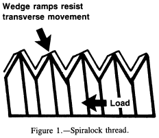
In a tapped hole the locking technique is normally on the fastener. One notable exception is the Spiralock tap shown in figure 1. The Spiralock thread form has a 30° wedge ramp at its root. Under clamp load the crests of the male threads are wedged tightly against the ramp. This makes lateral movement, which causes loosening under vibration, nearly impossible. Independent tests by some of the aerospace companies have indicated that this type of thread is satisfactory for moderate resistance to vibration. The bolt can have a standard thread, since the tapped hole does all the locking.
Locknuts
There are various types of locking elements, with the common principle being to bind (or wedge) the nut thread to the bolt threads. Some of the more common locknuts are covered here.
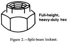
Split beam.-- The split-beam locknut (fig. 2) has slots in the top, and the thread diameter is undersized in the slotted portion. The nut spins freely until the bolt threads get to the slotted area. The split "beam" segments are deflected outward by the bolt, and a friction load results from binding of the mating threads.
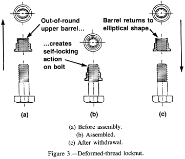
Deformed thread.-- The deformed-thread locknut (fig. 3) is a common locknut, particularly in the aerospace industry. Its advantages are as follows:
- The nut can be formed in one operation.
- The temperature range is limited only by the parent metal, its plating, or both.
- The nut can be reused approximately 10 times before it has to be discarded for loss of locking capability.
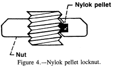
Nylok pellet.-- The Nylok pellet (of nylon) is usually installed in the nut threads as shown in figure 4. A pellet or patch projects from the threads. When mating threads engage, compression creates a counterforce that results in locking contact. The main drawback of this pellet is that its maximum operating temperature is approximately 250 °F. The nylon pellet will also be damaged quickly by reassembly.
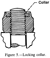
Locking collar and seal.-- A fiber or nylon washer is mounted in the top of the nut as shown in figure 5. The collar has an interference fit such that it binds on the bolt threads. It also provides some sealing action from gas and moisture leakage. Once again the limiting feature of this nut is the approximate 250 °F temperature limit of the locking collar.
A cost-saving method sometimes used instead of a collar or nylon pellet is to bond a nylon patch on the threads of either the nut or the bolt to get some locking action. This method is also used on short thread lengths, where a drilled hole for a locking pellet could cause severe stress concentration.
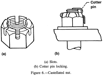
Castellated nut.-- The castellated nut normally has six slots as shown in figure 6(a). The bolt has a single hole through its threaded end. The nut is torqued to its desired torque value. It is then rotated forward or backward (depending on the user's preference) to the nearest slot that aligns with the drilled hole in the bolt. A cotter pin is then installed to lock the nut in place as shown in figure 6(b). This nut works extremely well for low-torque applications such as holding a wheel bearing in place.
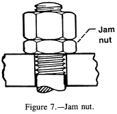
Jam nuts.-- These nuts are normally "jammed" together as shown in figure 7, although the "experts" cannot agree on which nut should be on the bottom. However, this type of assembly is too unpredictable to be reliable. If the inner nut is torqued tighter than the outer nut, the inner nut will yield before the outer nut can pick up its full load. On the other hand, if the outer nut is tightened more than the inner nut, the inner nut unloads. Then the outer nut will yield before the inner nut can pick up its full load. It would be rare to get the correct amount of torque on each nut. A locknut is a much more practical choice than a regular nut and a jam nut. However, a jam nut can be used on a turnbuckle, where it does not carry any of the tension load.
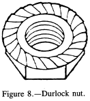
Serrated-face nut (or bolthead).-- The serrated face of this nut (shown in fig. 8) digs into the bearing surface during final tightening. This means that it cannot be used with a washer or on surfaces where scratches or corrosion could be a problem.
According to SPS Technologies, their serrated-face bolts (Durlock 180) require 110 percent of tightening torque to loosen them. Their tests on these bolts have shown them to have excellent vibration resistance.
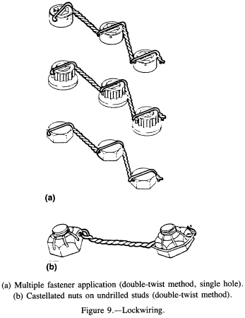
Lockwiring.-- Although lockwiring is a laborious method of preventing bolt or nut rotation, it is still used in critical applications, particularly in the aerospace field. The nuts usually have drilled corners, and the bolts either have throughholes in the head or drilled corners to thread the lockwire through. A typical bolthead lockwiring assembly is shown in figure 9(a), and a typical nut lockwiring assembly is shown in figure 9(b).
Direct interfering thread.-- A direct interfering thread has an oversized root diameter that gives a slight interference fit between the mating threads. It is commonly used on threaded studs for semipermanent installations, rather than on bolts and nuts, since the interference fit does damage the threads.
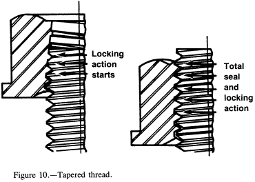
Tapered thread.-- The tapered thread is a variation of the direct interfering thread, but the difference is that the minor diameter is tapered to interfere on the last three or four threads of a nut or bolt as shown in figure 10.
Nutplates.-- A nutplate (fig. 11) is normally used as a blind nut. They can be fixed or floating. In addition, they can have most of the locking and sealing features of a regular nut. Nutplates are usually used on materials too thin to tap. They are used primarily by the aerospace companies, since their installation is expensive. At least three drilled holes and two rivets are required for each nutplate installation.

Locking Adhesives
Many manufacturers make locking adhesives (or epoxies) for locking threads. Most major manufacturers make several grades of locking adhesive, so that the frequency of disassembly can be matched to the locking capability of the adhesive. For example, Loctite 242 is for removable fasteners, and Loctite 271 is for tamperproof fasteners. Other manufacturers such as Bostik, ND Industries, Nylock, 3M, and Permaloc make similar products.
Most of these adhesives work in one of two ways. They are either a single mixture that hardens when it becomes a thin layer in the absence of air or an epoxy in two layers that does not harden until it is mixed and compressed between the mating threads. Note that the two-layer adhesives are usually put on the fastener as a "ribbon" or ring by the manufacturer. These ribbons or rings do have some shelf life, as long as they are not inadvertently mixed or damaged.
These adhesives are usually effective as thread sealers as well. However, none of them will take high temperatures. The best adhesives will function at 450 °F; the worst ones will function at only 200 °F.
Need a Bolted Joint Calculator?
Try this bolted joint calculator.
- stress analysis of a bolted joint
- accounts for preload, applied axial load, and applied shear load
Washers
Belleville Washers
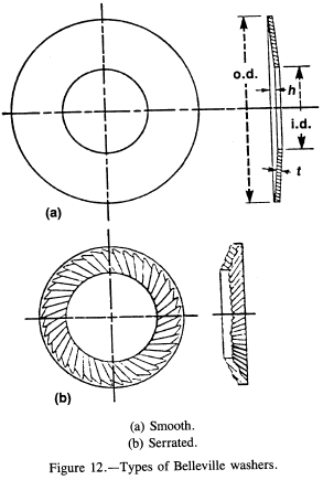
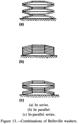
Belleville washers (fig. 12) are conical washers used more for maintaining a uniform tension load on a bolt than for locking. If they are not completely flattened out, they serve as a spring in the bolt joint. However, unless they have serrations on their surfaces, they have no significant locking capability. Of course, the serrations will damage the mating surfaces under them. These washers can be stacked in combinations as shown in figure 13 to either increase the total spring length (figs. 13(a) and (c)) or increase the spring constant (fig. 13(b)).
Lockwashers
The typical helical spring washer shown in figure 14 is made of slightly trapezoidal wire formed into a helix of one coil so that the free height is approximately twice the thickness of the washer cross section. They are usually made of hardened carbon steel, but they are also available in aluminum, silicon, bronze, phosphor-bronze, stainless steel, and K-Monel.
The lockwasher serves as a spring while the bolt is being tightened. However, the washer is normally flat by the time the bolt is fully torqued. At this time it is equivalent to a solid flat washer, and its locking ability is nonexistent. In summary, a lockwasher of this type is useless for locking.

Tooth (or Star) Lockwashers
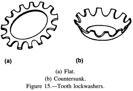
Tooth lockwashers (fig. 15) are used with screws and nuts for some spring action but mostly for locking action. The teeth are formed in a twisted configuration with sharp edges. One edge bites into the bolthead (or nut) while the other edge bites into the mating surface. Although this washer does provide some locking action, it damages the mating surfaces. These scratches can cause crack formation in highly stressed fasteners, in mating parts, or both, as well as increased corrosion susceptibility.
Self-Aligning Washers
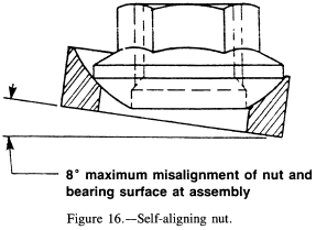
A self-aligning washer is used with a mating nut that has conical faces as shown in figure 16. Because there is both a weight penalty and a severe cost penalty for using this nut, it should be used only as a last resort. Maintaining parallel mating surfaces within acceptable limits (2° per SAE Handbook (ref. 4)) is normally the better alternative.
Need a Bolted Joint Calculator?
Try this bolted joint calculator.
- stress analysis of a bolted joint
- accounts for preload, applied axial load, and applied shear load
Inserts
An insert is a special type of device that is threaded on its inside diameter and locked with threads or protrusions on its outside diameter in a drilled, molded, or tapped hole. It is used to provide a strong, wear-resistant tapped hole in a soft material such as plastic and nonferrous materials, as well as to repair stripped threads in a tapped hole.
The aerospace industry uses inserts in tapped holes in soft materials in order to utilize small high-strength fasteners to save weight. The bigger external thread of the insert (nominally 118 in. bigger in diameter than the internal thread) gives, for example, a 10-32 bolt in an equivalent 5/16-18 nut.
In general, there are two types of inserts: those that are threaded externally, and those that are locked by some method other than threads (knurls, serrations, grooves, or interference fit). Within the threaded inserts there are three types: the wire thread, the self-tapping, and the solid bushing.
Threaded Inserts
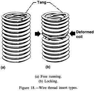
Wire thread.-- The wire thread type of insert (Heli-coil) is a precision coil of diamond-shaped CRES wire that forms both external and internal threads as shown in figure 17. The coil is made slightly oversize so that it will have an interference fit in the tapped hole. In addition, this insert is available with a deformed coil (fig. 18) for additional locking. The tang is broken off at the notch after installation.
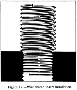
The wire thread insert is the most popular type for repair of a tapped hole with stripped threads, since it requires the least amount of hole enlargement. However, the solid bushing insert is preferred if space permits.
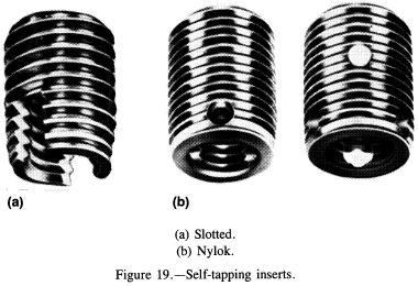
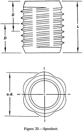
Self-tapping.-- Most of the self-tapping inserts are the solid bushing type made with a tapered external thread similar to a self-tapping screw (fig. 19). There are several different locking combinations, such as the Nylok plug (fig. 19(b)) or the thread-forming Speedsert deformed thread (fig. 20). An additional advantage of the thread-forming insert is that it generates no cutting chips, since it does not cut the threads. However, it can only be used in softer materials.
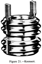
Solid bushing.-- Solid bushing inserts have conventional threads both internally and externally. A popular type is the Keensert shown in figure 21. The locking keys are driven in after the insert is in place. Another manufacturer uses a two-prong ring for locking. These inserts are also available with distorted external thread or Nylok plugs for locking.
Nonthreaded Inserts
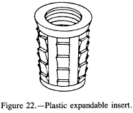
Plastic expandable.-- The most familiar of the nonthreaded inserts is the plastic expandable type shown in figure 22. This insert has barbs on the outside and longitudinal slits that allow it to expand outward as the threaded fastener is installed, pushing the barbs into the wall of the drilled hole. (See ref. 5.)
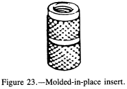
Molded in place.-- This type of insert (fig. 23) is knurled or serrated to resist both pullout and rotation. It is commonly used with ceramics, rubber, and plastics, since it can develop higher resistance to both pullout and rotation in these materials than self-tapping or conventionally threaded inserts. (See ref. 5.)
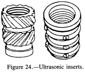
Ultrasonic.-- Ultrasonic inserts (fig. 24) have grooves in various directions to give them locking strength. They are installed in a prepared hole by pushing them in while they are being ultrasonically vibrated. The ultrasonic vibration melts the wall of the hole locally so that the insert grooves are "welded" in place. Since the area melted is small, these inserts do not have the holding power of those that are molded in place. Ultrasonic inserts are limited to use in thermoplastics. (See ref. 5.)
Need a Bolted Joint Calculator?
Try this bolted joint calculator.
- stress analysis of a bolted joint
- accounts for preload, applied axial load, and applied shear load
Threads
Types of Threads
Since complete information on most threads can be found in the ANSI standards (ref. 6), the SAE Handbook (ref. 4), and the National Institute of Standards and Technology (formerly the National Bureau of Standards) Handbook H-28 (ref. 7) no thread standards will be included in this handbook. The goal here is to explain the common thread types, along with their advantages and disadvantages. The common thread types are unified national coarse (UNC), unified national fine (UNF), unified national extra fine (UNEF), UNJC, UNJF, UNR, UNK, and constant-pitch threads.
Unified national coarse.-- UNC is the most commonly used thread on general-purpose fasteners. Coarse threads are deeper than fine threads and are easier to assemble without cross threading. The manufacturing tolerances can be larger than for finer threads, allowing for higher plating tolerances. UNC threads are normally easier to remove when corroded, owing to their sloppy fit. However, a UNC fastener can be procured with a class 3 (tighter) fit if needed (classes to be covered later).
Unified national fine.-- UNF thread has a larger minor diameter than UNC thread, which gives UNF fasteners slightly higher load-carrying and better torque-locking capabilities than UNC fasteners of the same identical material and outside diameter. The fine threads have tighter manufacturing tolerances than UNC threads, and the smaller lead angle allows for finer tension adjustment. UNF threads are the most widely used threads in the aerospace industry.
Unified national extra fine.-- UNEF is a still finer type of thread than UNF and is common to the aerospace field. This thread is particularly advantageous for tapped holes in hard materials and for thin threaded walls, as well as for tapped holes in thin materials.
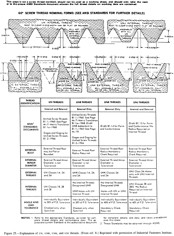
UNJC and UNJF threads.-- "J" threads are made in both external and internal forms. The external thread has a much larger root radius than the corresponding UNC, UNR, UNK, or UNF threads. This radius is mandatory and its inspection is required, whereas no root radius is required on UNC, UNF, or UNEF threads. Since the larger root radius increases the minor diameter, a UNJF or UNJC fastener has a larger net tensile area than a corresponding UNF or UNC fastener. This root radius also gives a smaller stress concentration factor in the threaded section. Therefore, high-strength (≥180 ksi) bolts usually have "J" threads.
UNR threads.-- The UNR external thread is a rolled UN thread in all respects except that the root radius must be rounded. However, the root radius and the minor diameter are not checked or toleranced. There is no internal UNR thread.
UNK threads.-- The UNK external threads are similar to UNR threads, except that the root radius and the minor diameter are toleranced and inspected. There is no internal UNK thread. According to a survey of manufacturers conducted by the Industrial Fasteners Institute, nearly all manufacturers of externally threaded fasteners make UNR rolled threads rather than plain UN. The only exception is for ground or cut threads.
Constant-pitch threads.-- These threads offer a selection of pitches that can be matched with various diameters to fit a particular design. This is a common practice for bolts of 1-in. diameter and above, with the pitches of 8, 12, or 16 threads per inch being the most common.
A graphical and tabular explanation of UN, UNR, UNK, and UNJ threads is given on page M-6 of reference 8. A copy (fig. 25) is enclosed here for reference.
Classes of Threads
Thread classes are distinguished from each other by the amounts of tolerance and allowance. The designations run from 1A to 3A and 1B to 3B for external and internal threads, respectively. A class 1 is a looser fitting, general-purpose thread; a class 3 is the closer-toleranced aerospace standard thread. (The individual tolerances and sizes for the various classes are given in the SAE Handbook (ref 4).)
Forming of Threads
Threads may be cut, hot rolled, or cold rolled. The most common manufacturing method is to cold form both the head and the threads for bolts up to 1 in. in diameter. For bolts above 1-in. diameter and high-strength smaller bolts, the heads are hot forged. The threads are still cold rolled until the bolt size prohibits the material displacement necessary to form the threads (up to a constant pitch of eight threads per inch). Threads are cut only at assembly with taps and dies or by lathe cutting.
Cold rolling has the additional advantage of increasing the strength of the bolt threads through the high compressive surface stresses, similar to the effects of shot peening. This process makes the threads more resistant to fatigue cracking.
Fatigue-Resistant Bolts
This section is located here: Fatigue-Resistant Bolts.
Fastener Torque
This section is located here: Fastener Torque.
Design Criteria
Finding Loads on Fastener Group
This section is located here: Finding Loads on Fastener Group.
Calculating Shank Diameter for "Number" Fastener
The shank diameter for a "number" fastener is calculated from
Diameter = 0.060 + 0.013 N
where N is the number (4, 6, 8, 10, 12) of the fastener. For example, the shank diameter of a no. 8 fastener is
Diameter = 0.060 + 0.013 (8) = 0.164 in.
Fastener Groups in Bearing (Shear Loading)
Whenever possible, bolts in shear should have a higher shear strength than the bearing yield strength of the materials they go through. Since the bolts have some clearance and position tolerances in their respective holes, the sheet material must yield in bearing to allow the bolt pattern to load all of the bolts equally at a given location in the pattern. Note that the sloppier the hole locations, the more an individual bolt must carry before the load is distributed over the pattern.
Bolts and rivets should not be used together to carry a load, since the rivets are usually installed with an interference fit. Thus, the rivets will carry all of the load until the sheet or the rivets yield enough for the bolts to pick up some load. This policy also applies to bolts and dowel pins (or roll pins) in a pattern, since these pins also have interference fits.
Fastener Edge Distance and Spacing
Common design practice is to use a nominal edge distance of 2D from the fastener hole centerline, where D is the fastener diameter. The minimum edge distance should not be less than 1.5D. The nominal distance between fasteners is 4D, but the thickness of the materials being joined can be a significant factor. For thin materials, buckling between fasteners can be a problem. A wider spacing can be used on thicker sheets, as long as sealing of surfaces between fasteners is not a problem.
Approximate Bearing and Shear Allowables
In the absence of specific shear and bearing allowables for materials, the following approximations may be used:
| Alloy and carbon steels: | Fsu = 0.6 Ftu |
| Stainless steels: | Fsu = 0.55 Ftu |
where Fsu is ultimate shear stress and Ftu is ultimate tensile stress. Since bearing stress allowables are empirical to begin with, the bearing allowable for any given metallic alloy may be approximated as follows:
Fbu = 1.5 Ftu
Fby = 1.5 Fty
where Fbu is ultimate bearing stress, Fby is yield bearing stress, and Fty is tensile yield stress.
Proper Fastener Geometry
Most military standard (MS) and national aerospace standard (NAS) fasteners have coded callouts that tell the diameter, grip length, drilling of the head or shank, and the material (where the fastener is available in more than one material). Rather than listing a group of definitions, it is easier to use the NAS 1003 to NAS 1020 (fig. 32) as an example to point out the following:
- The last two digits give the fastener diameter in sixteenths of an inch.
- The first dash number is the grip length in sixteenths of an inch.
- The letters given with the dash number indicate the head and/or shank drilling.
In addition, an identifying letter or dash number is added to indicate the fastener material. However, this systematic practice is not rigidly followed in all MS and NAS fastener standards.
Shear Heads and Nuts
In the aerospace industry the general ground rule is to design such that fasteners are primarily in shear rather than tension. As a result, many boltheads and nuts are made about one-half as thick as normal to save weight. These bolts and nuts are referred to as shear bolts and shear nuts, and care must be used in never specifying them for tension applications. The torque table values must also be reduced to one-half for these bolts and nuts.
Use of Proper Grip Length
Standard design practice is to choose a grip length such that the threads are never in bearing (shear). Where an exact grip length is not available, the thickness of the washers used under the nut or bolthead can be varied enough to allow proper grip.
Bolthead and Screwhead Styles
Although the difference between bolts and screws is not clearly defined by industry, at least the head styles are fairly well defined. The only discrepancy found in figure 33 is that the plain head, with a square shoulder, is more commonly called a carriage bolthead. The angle of countersunk heads (flat) can vary from 60° to 120°, but the common values are 82° and 100°.

Counterfeit Fasteners
In the past two years a great deal of concern and publicity about counterfeit fasteners has surfaced. The counterfeit case with the most documentation is the deliberate marking of grade 8.2 boron bolts as grade 8 bolts.
Grade 8.2 bolts are a low-carbon (0.22 percent C) boron alloy steel that can be heat treated to the same room-temperature hardness as grade 8 medium-carbon (0.37 percent C) steel. However, the room- and elevated-temperature strengths of the grade 8.2 bolts drop drastically if they are exposed to temperatures above 500 °F. Grade 8 bolts can be used to 800 °F with little loss of room-temperature strength.
Other fasteners marked as MS and NAS but not up to the respective MS or NAS specification have shown up; however, documentation is not readily available. Since these fasteners are imported and have no manufacturer's identification mark on them, it is not possible to trace them back to the guilty manufacturer. U.S. Customs inspections have not been effective in intercepting counterfeit fasteners.
Another problem with fasteners has been the substitution of zinc coating for cadmium coating. If a dye is used with the zinc, the only way to detect the difference in coatings is by chemical testing.
Federal legislation to establish control of fastener materials from the material producer to the consumer is being formulated.
Bolthead Identification
Identifying an existing non-MS, non-NAS, or non-Air Force-Navy bolt is usually a problem. Each manufacturer seems to have a different system. Frank Akstens of Fastener Technology International magazine (ref. 10) has compiled a good listing of several hundred "common" bolts. His entire compilation is enclosed as appendix A of this report. An international guide to bolt manufacturer's identification symbols has also been published by Fastener Technology International magazine.
Fastener Strength
Allowable strengths for many types of fasteners are given in MIL-HDBK-5 (ref. 9). Ultimate shear and tensile strengths of various threaded fasteners are given in appendix B of this report.
Rivets and Lockbolts
This section is located here: Rivets and Lockbolts.
References
- Sliney, H.E.: High Temperature Solid Lubricants -- 1. Layer Lattice Compounds and Graphite. Mech. Eng., vol. 96, no. 2, Feb. 1974, pp. 18-22.
- Prevention of Material Deterioration: Corrosion Control Course -- U.S. Army Logistics Engineering Directorate -- Nov. 1970.
- ASM Metals Handbook. 9th ed., Vols. 1, 2, 3, 5, 13, American Society for Metals, Metals Park, OH.
- SAE Handbook. SAE, 1968.
- 1987 Fastening, Joining & Assembly Reference Issue. Mach. Des., vol. 59, no. 27, Nov. 19, 1987.
- Unified Inch Screw Threads (UN and UNR Thread Form). ANSI B1.1-1982, American National Standards Institute, New York, NY, 1982.
- Screw Thread Standards for Federal Services, Part 1 -- Unified UNJ Unified Miniature Screw Threads. National Bureau of Standards Handbook, NBS-H28-1969-PT-1, 1969.
- Fastener Standards. 5th ed., Industrial Fasteners Institute, Cleveland, OH, 1970.
- Metallic Materials and Elements for Aerospace Vehicle Structures. MIL-HDBK-5E, Department of Defense, June 1987.
- Fastener Technology International Magazine, Solon, Ohio, Oct. 1985 through Feb. 1987 Editions.
