Loads on Fastener Groups
This page provides the sections on calculating shear and tensile loads on a fastener group (bolt pattern) from Barrett, "Fastener Design Manual," NASA Reference Publication 1228, 1990.
Other related chapters from the NASA "Fastener Design Manual" can be seen to the right.
- Fastener Design Criteria
- Fastener Torque
- Loads on Fastener Groups
- Fatigue Resistant Bolts
- Rivets and Lockbolts
Finding Shear Loads on Fastener Group
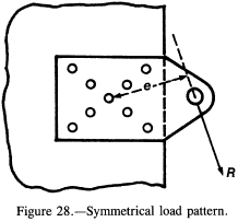
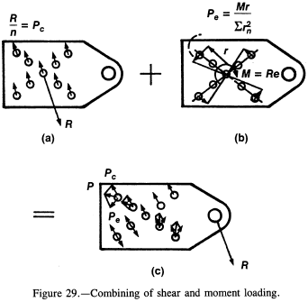
When the load on a fastener group is eccentric, the first task is to find the centroid of the group. In many cases the pattern will be symmetrical, as shown in figure 28. The next step is to divide the load R by the number of fasteners n to get the direct shear load Pc (fig. 29(a)). Next, find Σ rn2 for the group of fasteners, where rn is the radial distance of each fastener from the centroid of the group. Now calculate the moment about the centroid (M = re from fig. 28). The contributing shear load for a particular fastener due to the moment can be found by the formula
$$ P_e = { M r \over \sum r_n^2 } $$where r is the distance (in inches) from the centroid to the fastener in question (usually the outermost one). Note that this is analogous to the torsion formula, f = Tr / J, except that Pe is in pounds instead of stress. The two loads (Pc and Pe) can now be added vectorally as shown in figure 29(c) to get the resultant shear load P (in pounds) on each fastener. Note that the fastener areas are all the same here. If they are unequal, the areas must be weighted for determining the centroid of the pattern.
Further information on this subject may be found in references 1 and 2.
Need a Bolt Pattern Calculator?
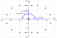
Try this bolt pattern force distribution calculator, which allows for applied forces to be distributed over bolts in a pattern.
Finding Tension Loads on Fastener Group
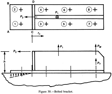
This procedure is similar to the shear load determination, except that the centroid of the fastener group may not be the geometric centroid. This method is illustrated by the bolted bracket shown in figure 30.
The pattern of eight fasteners is symmetrical, so that the tension load per fastener from P1 will be P1/8. The additional moment P2 h will also produce a tensile load on some fasteners, but the problem is to determine the "neutral axis" line where the bracket will go from tension to compression. If the plate is thick enough to take the entire moment P2 h in bending at the edge AB, that line could be used as the heeling point, or neutral axis. However, in this case, I have taken the conservative approach that the plate will not take the bending and will heel at the line CD. Now the Σ rn2 will only include bolts 3 to 8, and the rn's (in inches) will be measured from line CD. Bolts 7 and 8 will have the highest tensile loads (in pounds), which will be P = PT + PM, where PT = P1/8 and
$$ P_m = { M r \over \Sigma r_n^2 } = { P_2 ~h ~r_7 \over \Sigma r_n^2 } $$An alternative way of stating this relationship is that the bolt load is proportional to its distance from the pivot axis and the moment reacted is proportional to the sum of the squares of the respective fastener distances from the pivot axis.
At this point the applied total tensile load should be compared with the total tensile load due to fastener torque. The torque should be high enough to exceed the maximum applied tensile load in order to avoid joint loosening or leaking. If the bracket geometry is such that its bending capability cannot be readily determined, a finite element analysis of the bracket itself may be required.
Combining Shear and Tensile Fastener Loads
When a fastener is subjected to both tensile and shear loading simultaneously, the combined load must be compared with the total strength of the fastener. Load ratios and interaction curves are used to make this comparison. The load ratios are
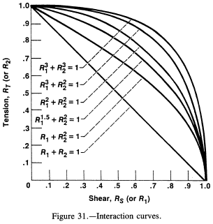
$$ R_S \text{ (or } R_1 \text{)} = { \text{Actual shear load} \over \text{Allowable shear load} } $$ $$ R_T \text{ (or } R_2 \text{)} = { \text{Actual tensile load} \over \text{Allowable tensile load} } $$The interaction curves of figure 31 are a series of curves with their corresponding empirical equations. The most conservative is R1 + R2 = 1 and the least conservative is R13 + R23 = 1. This series of curves is from an old edition of MIL-HDBK-5. It has been replaced by a single formula, RS3 + RT2 = 1, in the latest edition (ref. 3). However, it is better to use RS + RT = 1 if the design can be conservative with respect to weight and stress.
Note that the interaction curves do not take into consideration the friction loads from the clamped surfaces in arriving at bolt shear loads. In some cases the friction load could reduce the bolt shear load substantially.
The margin of safety for a fastener from figure 31 is
$$ MS = { 1 \over R_S^x + R_T^y } - 1 $$depending on which curve is used. However, note that RS x + RT y < 1 is a requirement for a positive margin of safety. This formula also illustrates why high torque should not be applied to a bolt when the dominant load is shear.
The margin of safety is calculated for both yield and ultimate material allowables, with the most critical value controlling the design. A material with a low yield will be critical for yield stress, and a material with a high yield will normally be critical for ultimate stress.
Need a Bolt Pattern Calculator?
Try this bolt pattern force distribution calculator, which allows for applied forces to be distributed over bolts in a pattern.
Calculating Pullout Load for Threaded Hole
In many cases a bolt of one material may be installed in a tapped hole in a different (and frequently lower strength) material. If the full strength of the bolt is required, the depth of the tapped hole must be determined for the weaker material by using the formula
$$ P = { \pi d_m F_s L \over 3 } $$where
| P | pullout load, lb |
| dm | mean diameter of threaded hole, in. (≈ pitch diameter of threads) |
| Fs | material ultimate or yield shear stress |
| L | length of thread engagement, in. |
The 1/3 factor is empirical. If the threads were perfectly mated, this factor would be 1/2, since the total cylindrical shell area of the hole would be split equally between the bolt threads and the tapped hole threads. The 1/3 is used to allow for mismatch between threads.
Further information on required tapped hole lengths is given in reference 4.
References
- Peery, D.J.: Aircraft Structures. McGraw-Hill, 1950.
- Grinter, L.: Theory of Modern Steel Structures. Vol. I, Macmillan Co., 1955.
- Metallic Materials and Elements for Aerospace Vehicle Structures. MIL-HDBK-5E, Department of Defense, June 1987.
- Faupel, J.H.; and Fisher, F.E.: Engineering Design, 2nd ed., Wiley & Sons, 1981.
