Partial Tension Beam Bending
This page provides the sections on partial tension beam bending from the "Stress Analysis Manual," Air Force Flight Dynamics Laboratory, October 1986.
Other related chapters from the Air Force "Stress Analysis Manual" can be seen to the right.
- Simple Beam Bending
- Shear Web Beam Bending
- Partial Tension Beam Bending
- Beam Forces & Moments
- Beam Columns
- Beam Torsion
Nomenclature
| Af | = | cross-sectional area of tension or compression flange |
| Au | = | cross-sectional area of upright or stiffener |
| Aue | = | effective cross-sectional area of upright or stiffener |
| C1, C2, C3 | = | stress concentration factors |
| Cr | = | rivet factor |
| cf | = | distance from neutral axis of flange to the extreme fiber of flange |
| D | = | diameter |
| d | = | stiffener spacing |
| e | = | distance from centroid of upright to web |
| Fco | = | column yield stress (allowable column stress at L'/ρ = 0) |
| Fo | = | ultimate allowable compressive stress for forced crippling |
| Fs | = | allowable web shear stress |
| Fscr | = | critical (or initial) buckling stress |
| fb | = | calculated primary bending stress |
| fs | = | calculated shear stress |
| fu | = | calculated average compressive stress in upright |
| fumax | = | calculated maximum compressive stress in upright |
| h | = | distance between centroids of flanges |
| I | = | moment of inertia |
| If | = | average moment of inertia of beam flanges |
| Is | = | required moment of inertia of upright or stiffener about its base |
| k | = | diagonal tension factor |
| L | = | length |
| L' | = | effective length of beam |
| M | = | applied bending moment |
| Msb | = | secondary bending moment in flange |
| q | = | shear flow |
| q' | = | beam shear at a distance of 2h/3 from the beam end |
| qr | = | shear load of web to flange rivets (lb/in) |
| qt | = | tension load on web to upright rivets (lb/in) |
| qt' | = | increased tension load on web to upright rivets (lb/in) |
| t | = | thickness |
| tu | = | upright thickness |
| V | = | shear force |
| ρ | = | radius of gyration |
1.3.3 Introduction to Partial Tension Field Beams in Bending
A tension field beam is defined to be one for which the web is incapable of supporting any compressive load, and thus buckles upon application of any load, and the web of a stiffened shear resistant beam is designed so that it will not buckle. The web of a partial tension field beam is capable of resisting compressive loads, but buckles at a load less than the ultimate beam load. The vertical stiffeners in a partial tension field beam serve to resist a compressive load and also increase the web buckling stress by dividing the web into smaller unsupported rectangles.
The curves given for partial tension field beams give reasonable assurance of conservative strength predictions provided that normal design practices and proportions are used. The most important points are:
- The ratio of the thickness of the uprights to that of the web, tu/t, should be greater than 0.6.
- The upright spacing, d, should be in the range 0.2 < d/h < 1.0.
- The method of analysis presented here is applicable only to beams with webs in the range 115 < h/t < 1500.
In the following presentation, it is considered sufficiently accurate to take the distance between flange centroids, h, as the web height and upright length.
The methods of analysis of the web, uprights, flanges, and rivets of partial tension field beams are given in the following sections. The end of a partial tension field beam must be treated differently and is covered in Section 1.3.3.9. If a partial tension field beam has access holes, it should be treated according to Section 1.3.3.14.
1.3.3.1 Webs of Partial Tension Field Beams
The web shear flow and shear stress of a partial tension field beam are given to a close degree of approximation by Equations (1-20) and (1-21):
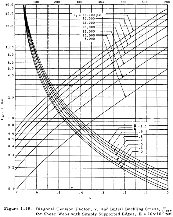
The diagonal tension field factor, k, of a partial tension field beam specifies the portion of the total shear that is carried by the diagonal tension action of the web. This factor can be found from Figure 1-18 as a function of the web shear stress, fs, and the ratios d/t and d/h. This curve is based on the assumption that the shear panel has simply supported edges. The accuracy, however, is sufficient for tension field beams whose webs have varying degrees of edge restraint. It is recommended that the diagonal tension factor at ultimate load satisfy the following inequality:
This criterion is presented in tabular form in Table 1-5.
| t | 0.020 | 0.025 | 0.032 | 0.040 | 0.051 | 0.064 | 0.072 | 0.081 | 0.091 | 0.102 | 0.125 | 0.156 | 0.188 | 0.250 |
| 0.78 − (t − 0.012)1/2 | 0.69 | 0.67 | 0.64 | 0.61 | 0.58 | 0.55 | 0.53 | 0.52 | 0.50 | 0.48 | 0.44 | 0.40 | 0.36 | 0.29 |
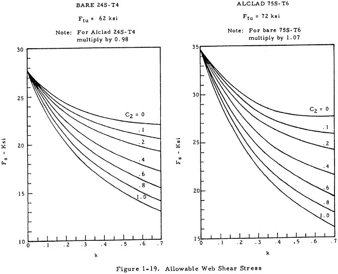
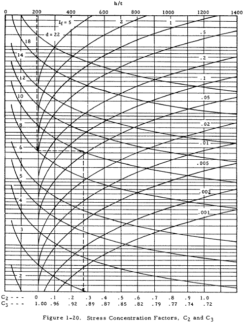
The allowable web shear stress, Fs, can be obtained from Figure 1-19 for 75S-T6 or 24S-T4 aluminum sheet. These values are based on tests of long webs subjected to loads approximating pure shear and contain an allowance for the rivet factor, Cr. The allowance for rivet factor is included because the ultimate allowable shear stress based on the gross section is almost constant in the normal range of the rivet factor (Cr > 0.6). The values of Fs are given as a function of the stress concentration factor, C2, which can be found from Figure 1-20 as a function of h/t, d, and If. The higher values of C2 are largely theoretical, but a few scattered tests indicate that the values of C2 become increasingly conservative in the higher ranges.
Need a Beam Calculator?
Try this beam calculator.
- Calculates stresses and deflections in straight beams
- Builds shear and moment diagrams
- Can specify any configuration of constraints, concentrated forces, and distributed forces
1.3.3.2 Effective Area of the Upright of a Partial Tension Field Beam
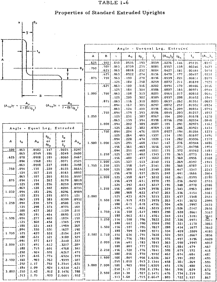
The total cross-sectional area of the uprights for double or single uprights is designated as Au. In order to make the design charts apply to both single and double uprights, the following effective upright areas, Aue are to be used in the analysis.
For double uprights, symmetrical with respect to the web,
For single uprights,
where ρ is the radius of gyration of the stiffener and e is the distance from the centroid of the stiffener to the center of the web. If the upright itself has a very deep web, Aue should be taken to be the sum of the cross-sectional area of the attached leg and an area 12tu2 (i.e., the effective width of the outstanding leg is 12 times tu.
The properties of standard extruded angles commonly used as uprights may be obtained from Table 1-6.
1.3.3.3 Design Criteria for the Uprights of a Partial Tension Field Beam
The uprights or web stiffeners of a partial tension field beam must have a sufficient moment of inertia to prevent buckling of the web system as a whole before formation of the tension field, as well as to prevent column failure under the loads imposed on the upright by the tension field. The upright must also be thick enough to prevent forced crippling failure caused by the waves of the buckled web. This forced crippling failure is almost always the most critical.
1.3.3.4 Moment of Inertia of the Uprights of a Partial Tension Field Beam
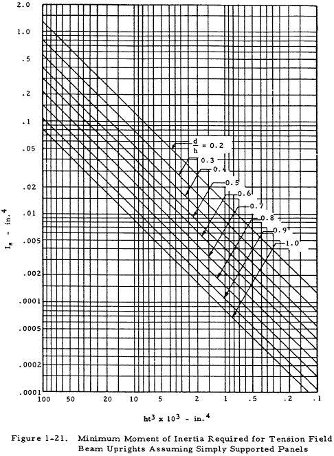
The required moment of inertia of the upright about its base (the surface attached to the web) is given in Figure 1-21 as a function of ht3 and d/h. These curves are essentially derived by equating the critical buckling stress of the sheet between the stiffeners to the general instability stress of the web as a whole.
1.3.3.5 Computed Stresses in the Uprights of a Partial Tension Field Beam
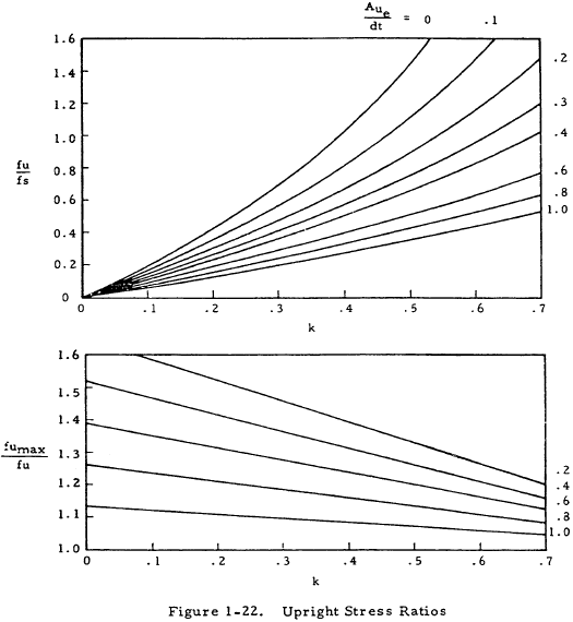
The lengthwise average stress in the upright at the surface of attachment to the web, fu, may be obtained from Figure 1-22 as a function of k, Aue/td, and fs as
The upright stress varies from a maximum at the neutral axis of the beam to a minimum at the ends of the upright. The maximum stress, fumax, may be obtained from Figure 1-22 as a function of k, d/h, and fu as
Need a Beam Calculator?
Try this beam calculator.
- Calculates stresses and deflections in straight beams
- Builds shear and moment diagrams
- Can specify any configuration of constraints, concentrated forces, and distributed forces
1.3.3.6 Allowable Stresses in the Uprights of a Partial Tension Field Beam
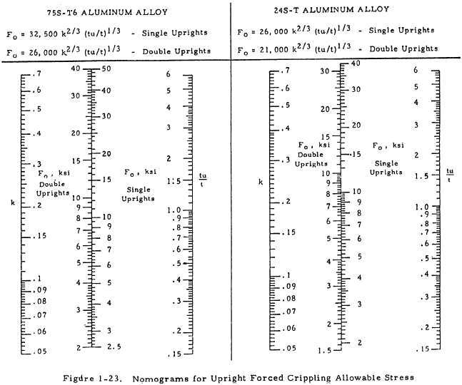
The maximum upright stress, fumax, should be checked against an allowable forced crippling stress, F0 , which is obtained from Figure 1-23. If the upright has legs of unequal thickness, the thickness of the leg attached to the web should be used to determine the ratio tu/t. In the case of double uprights, fumax should also be checked against the allowable natural crippling stress of the flange.
The stress, fu, should be no greater than the column yield stress, Fco (the stress at L'/ρ = 0). The centroidal upright stress, fcent = fu Aue/Au, should be checked against an allowable column stress, Fcol. Fco and Fcol can be found from the column curves in Chapter 2.
For simplicity, the effective column length of the upright, h', may be taken as h, since this effect is rarely critical. However, the following values of h' may be used if necessary:
for double uprights, and
for single uprights.
1.3.3.7 Flanges of Partial Tension Field Beams
The total stress in the flanges of a partial tension field beam is the result of the superposition of three individual stresses: the primary beam stress, fb, the compressive stress, ff, caused by the horizontal component of the diagonal tension in the web, and the secondary bending stress, fsb, caused by the distributed vertical component of the diagonal tension.
The primary beam stress is given by
The compressive stresses due to the horizontal component of diagonal tension is given by
where k is the diagonal tension field factor which may be found by referring to Figure 1-18. The secondary bending moment due to the distributed vertical component of diagonal tension is given by
where C3 is given in Figure 1-20. Msb is the maximum moment in the flange and exists in the portion of the flange over the uprights. If C3 and k are near unity, the secondary bending moment in the flange midway between the uprights is half as large as that given and of opposite sign. The secondary bending stress is then
where (If / cf) is the section modulus of the flange. The total stress in the flange is equal to fb + fs + fsb.
Need a Beam Calculator?
Try this beam calculator.
- Calculates stresses and deflections in straight beams
- Builds shear and moment diagrams
- Can specify any configuration of constraints, concentrated forces, and distributed forces
1.3.3.8 Rivets in Partial Tension Field Beams
Three types of rivets must be analyzed in partial tension field beams. These are web-to-flange rivets, web-to-upright rivets, and upright-to-flange rivets.
1.3.3.8.1 Web-to-Flange Rivets in a Partial Tension Field Beam
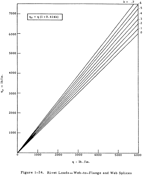
The shear load per inch acting on the web-to-flange rivets in partial tension field beams is given in Figure 1-24. The rivet factor, Cr, should be greater than 0.6 to justify the allowable web stresses used in Section 1.3.3.1 and to avoid undue stress concentration.
1.3.3.8.2 Web-to-Upright Rivets in Partial Tension Field Beam
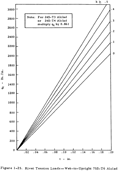
The tensile load per inch acting on the web-to-upright rivets is given in Figure 1-25. This tensile load is a result of the prying action of the buckled web. Although these loads reflect time-tested practice, they should be considered only tentative because of the limited test data presently available. The tensile load criteria is believed to insure a satisfactory design as far as shear strength is concerned.
1.3.3.8.3 Upright-to-Flange Rivets in a Partial Tension Field Beam
The shear load on the upright-to-flange rivets in a partial tension field beam is given by
where fu is the average compressive stress in the upright and Aue is the effective area of the upright as given in Section 1.3.3.2.
Need a Beam Calculator?
Try this beam calculator.
- Calculates stresses and deflections in straight beams
- Builds shear and moment diagrams
- Can specify any configuration of constraints, concentrated forces, and distributed forces
1.3.3.9 Ends of Partial Tension Field Beams
The end of a partial tension field beam must be specially handled since the web is discontinuous at the end and the tension component of web stress must be transferred to the flanges in the end panel.
The following treatment is based on the assumption that the basic beam shear, q, is constant over a length 2h/3 from the end of the beam. When the basic beam shear, q, varies over this length, the terms \((q + 1.5 kq)\), \((q + 1.0 kq)\), and \((q ~kh / 4 A_u )\) should be replaced by the terms \((q + 1.5 kq')\), \((q + 1.0 kq')\), and \((q' ~kh / 4 A_u )\), respectively, where q is the actual beam shear at the point being considered, and q' is the beam acting at a distance 2h/3 from the end of the beam.
1.3.3.10 Webs at the Ends of Partial Tension Field Beams
The web in one corner must carry a shear flow of \(q + 1.5 kq\). If reinforcement is necessary, a doubler of the dimensions shown in Figure 1-26 should be added to the web, resulting in a combined shear strength of \(q + 1.5 kq\). This is usually necessary in one corner only. If the applied shear flow is opposite to that shown in Figure 1-26, the doubler should be attached to the lower corner of the web. The shear flow in the web in the corner not reinforced is \(q - 1.5 kq\), where q is the shear flow in the web at points removed from the end.
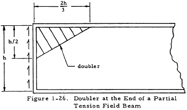
If the shear can act in either direction, double reinforcement may be necessary. In general, the basic web is capable of carrying about a 60% reversal of shear without double reinforcement.
1.3.3.11 Uprights at the Ends of Partial Tension Field Beams
The following stresses act simultaneously on the end stiffener of a partial tension field beam:
- A compressive stress due to the vertical component of web diagonal tension. This compressive stress varies from \((f_u - f_{umax}/2)\) at either end to \( f_{umax}/2 \) at the midpoint of the stiffener.
- A compressive stress due to the variable shear flow along the end stiffener. The equivalent shear flow distribution curve is assumed to vary linearly from \((q - 1.0 kq)\) at one corner to \((q + 1.0 kq)\) at the other corner. This compressive stress builds up from zero at either end of the stiffener to \( kqh / 4 A_u \) at the midpoint of the stiffener.
Thus, the maximum compressive stress in the end stiffener (exclusive of additional external loads acting) is equal to
This stress should be compared with the lower of Fo or Fcc for the upright in computing the margin of safety.
1.3.3.12 Rivets at the Ends of Partial Tension Field Beams
The doubler should be attached to the web in accordance with Table 1-7. The diagonal edge of the doubler should be attached with a minimum of two rows of rivets with a minimum distance between rows of four rivet diameters. The strength of this attachment in lb/in should be equal to the thickness of the doubler times 30,000 psi.
| Doubler Gage | Rivet Size | Rivet Spacing |
|---|---|---|
| 0.020 - 0.032 | AD-4 | 1.5 in. on centers |
| 0.040 - 0.051 | AD-5 | 2.0 in. on centers |
| 0.064 & greater | DD-6 | 2.5 in. on centers |
The web-to-flange attachment adjacent to the doubler must be strong enough to carry a shear flow of \((q + 1.5 ~q) (1 + 0.414 ~k) ~\text{lb/in}\). The other flange attachment must carry a shear flow of \(q ~(1 + 0.414 ~k) ~\text{lb/in}\).
The attachment of the end stiffener of a partial tension field beam to the web must be strong enough to carry a shear flow of \((q + 1.5 ~kq)(1 + 0.414 ~k) ~\text{lb/in}\) in the region of the doubler and \(q ~(1 + 0.414 ~k)\) elsewhere.
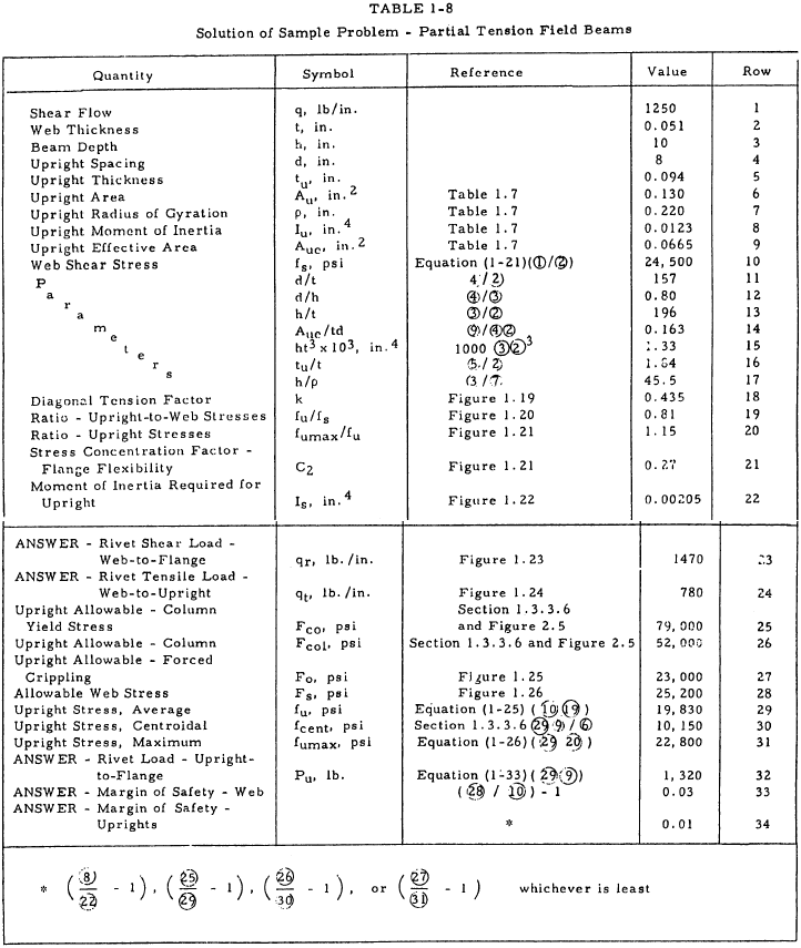
1.3.3.13 Sample Problem - Partial Tension Field Beams
Given: The partial tension field beam shown in Figure 1-27.
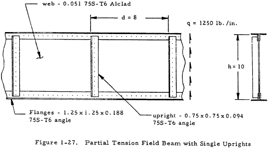
Find: The margins of safety of web and uprights and the rivet loads.
Solution: The method of obtaining the desired quantities is summarized in Table 1-8.
Need a Beam Calculator?
Try this beam calculator.
- Calculates stresses and deflections in straight beams
- Builds shear and moment diagrams
- Can specify any configuration of constraints, concentrated forces, and distributed forces
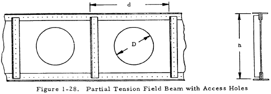
1.3.3.14 Partial Tension Field Beams with Access Holes
Figure 1-28 shows a partial tension field beam with access holes of diameter, D. Such a beam may be analyzed in the same manner as one without access holes except that the substitutions described in Sections 1.3.3.15, 1.3.3.16, and 1.3.3.17 must be made.
1.3.3.15 Webs of Partial Tension Field Beams with Access Holes
The method of analyzing webs, given in Section 1.3.3.1, should be used for partial tension field beams with access holes except that the allowable web shear stress, Fs, must be replaced by a reduced allowable web shear stress given by
where the design reduction factors, C4 and C5, are given in Figure 1-29. This method gives good correlation with tests if beam parameters are in the following ranges:
$$ 0.020 ~\text{in} < t < 0.132 ~\text{in} $$ $$ 0.040 ~\text{in} < t_u < 0.079 ~\text{in} $$ $$ 7.4 ~\text{in} < h < 19.4 ~\text{in} $$ $$ 7.0 ~\text{in} < d < 18.0 ~\text{in} $$ $$ 2.375 ~\text{in} < D < 5.875 ~\text{in} $$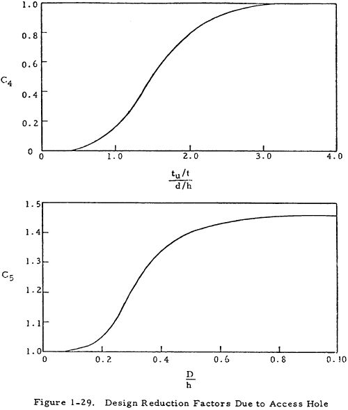
1.3.3.16 Uprights of Partial Tension Field Beams with Access Holes
The method of analyzing uprights, given in Sections 1.3.3.2 through 1.3.3.6, may be used for partial tension field beams with access holes except that the forced crippling allowable, Fo, should be replaced by a reduced forced crippling allowable given by
1.3.3.17 Rivets in Partial Tension Beams with Access Holes
The method given in Section 1.3.3.8 for analyzing rivets may be used for partial tension field beams with holes except that the tensile load on the web-to-upright rivets, qt, should be replaced by an increased load given by
