Beam Torsion
This page provides the sections on beam torsion from the "Stress Analysis Manual," Air Force Flight Dynamics Laboratory, October 1986.
Other related chapters from the Air Force "Stress Analysis Manual" can be seen to the right.
Nomenclature
| A | = | cross-sectional area |
| a | = | 1/2 the major diameter of an ellipse |
| a | = | linear dimension |
| b | = | 1/2 the minor diameter of an ellipse |
| b | = | width of section |
| b | = | developed length of thin section |
| b | = | linear dimension |
| c | = | linear dimension |
| D | = | diameter |
| d | = | linear dimension |
| Fst | = | torsional modulus of rupture |
| Fsu | = | ultimate stress in pure shear |
| Fsy | = | yield stress in pure shear |
| Ftu | = | ultimate tensile stress |
| fs | = | calculated shear stress |
| G | = | modulus of elasticity in shear |
| h | = | height or depth - height of shear web beam between centroids of flanges |
| Ip | = | polar moment of inertia |
| L | = | length |
| p | = | pressure |
| q | = | shear flow |
| r | = | radius |
| ri | = | inside radius |
| ro | = | outside radius |
| S | = | tension force on edge of membrane (lb/in) |
| s | = | distance measured along curved path |
| T | = | torque |
| Tmax | = | maximum allowable torque |
| t | = | thickness |
| te | = | effective thickness |
| ts | = | skin thickness |
| tst | = | thickness of closed stiffener |
| θ | = | angle of twist of beam |
| x, y, z | = | rectangular coordinates |
1.5 Introduction to Beams in Torsion
For purposes of discussion, beams in torsion are broken into two categories: circular beams, which are treated in Section 1.5.1, and noncircular beams, which are treated in Section 1.5.2. Circular beams are further divided into those with uniform cross sections (Section 1.5.1.1) and those with nonuniform cross sections (Section 1.5.1.2). Noncircular beams are divided into open noncircular beams (Section 1.5.2.1) and closed or hollow ones (Section 1.5.2.2), and the effect of end restraint on noncircular beams is treated in Section 1.5.2.3.
Section 1.5.3 treats the membrane and sandheap analogies for beams in torsion. Since the loading of the wires of helical springs is primarily torsional, they are listed under beams in torsion and treated in Section 1.5.4.
1.5.1 Circular Beams in Torsion
This section considers the torsion of solid or concentrically hollow circular beams.
1.5.1.1 Uniform Circular Beams in Torsion
Figure 1-42 shows a uniform circular beam in pure torsion. If the stresses in such a beam are in the elastic range, the stress distribution at a cross section is as shown in Figure 1-43.
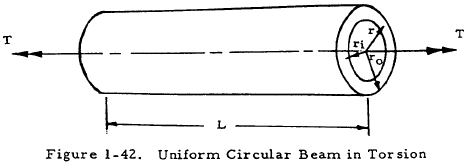
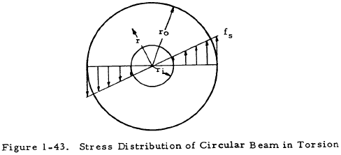
The shear stress at a distance r from the center is given by
The angle of twist of the beam is
Inserting the value of Ip for a circular cross section into Equations (1-45) and (1-46) gives
and
In order to treat solid circular shafts, ri may be set equal to zero in Equations (1-47) and (1-48).
It should be noted that Equations (1-47) and (1-48) apply only to beams with circular cross sections.
The maximum shear stress occurs at the outside surfaces of the beam and may be computed by setting r equal to ro in Equation (1-47). The maximum tensile and compressive stresses also occur at the outside surface and both are equal in magnitude to the maximum shear stress.
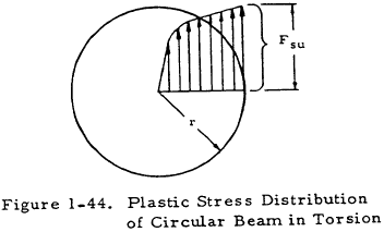
If a circular beam is twisted beyond the yield point until the outer portions are at the ultimate torsional stress, a stress distribution such as that shown in Figure 1-44 is obtained. The maximum torque that such a beam may sustain in static loading is given by
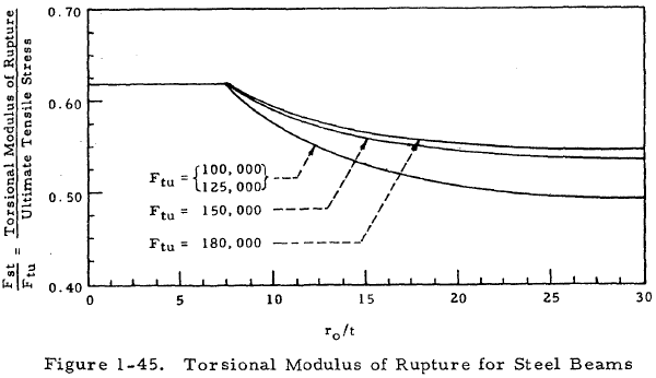
where Fst is designated as the torsional modulus of rupture. This torsional modulus of rupture is shown graphically for steel beams in Figure 1-45.
In many cases, the torsional modulus of rupture of a material may not be available. These may be treated by assuming the uniform shear stress distribution shown in Figure 1-46.
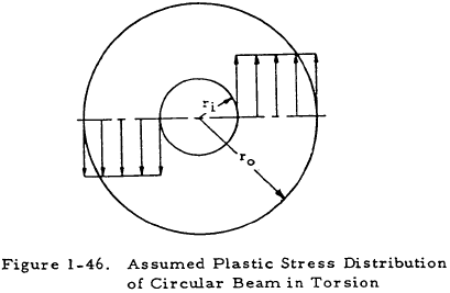
The magnitude of the uniform shear stress may be assumed to be equal to the yield shear stress (Fsy) for conservative results or the ultimate shear stress (Fsu) for nonconservative results. In the first case, the maximum torque in the beam may be expressed as
and in the second case, the maximum torque in the beam may be expressed as
It should be noted that the possibility of crippling in thin-walled tubes was not considered in the previous discussion. Crippling of circular tubes is treated in Chapter 8. These tubes should be checked for crippling.
Need a Beam Calculator?
Try this beam calculator.
- Calculates stresses and deflections in straight beams
- Builds shear and moment diagrams
- Can specify any configuration of constraints, concentrated forces, and distributed forces
1.5.1.2 Nonuniform Circular Beams in Torsion
When a circular beam of nonuniform cross section is twisted, the radii of a cross section become curved. Since the radii of a cross section were assumed to remain straight in the derivation of the equations for stress in uniform circular beams, these equations no longer hold if a beam is nonuniform. However, the stress at any section of a nonuniform circular beam is given with sufficient accuracy by the formulas for uniform bars if the diameter changes gradually. If the change in section is abrupt, as at a shoulder with a small fillet, a stress concentration must be applied as explained in Chapter 10.

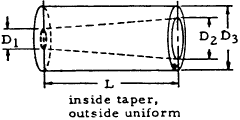
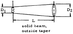
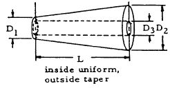
If its diameter changes gradually, its angle of twist is
This equation is used to obtain the formulas for θ for various beams of uniform taper that are shown in Table 1-13.
| Type of Beam | Angle of Twist |
|---|---|
|
$$
\begin{eqnarray}
\theta &=& { 8 T L \over \pi G (D_2 - D_1) D_3^3 } ~ \Bigg\{ 2 \arctan{\left({D_2 \over D_3}\right)} \nonumber \\
&-& 2 \arctan{\left({D_1 \over D_3}\right)} + \ln{\left[ \left({ D_3 + D_2 \over D_3 - D_2 }\right) \left({ D_3 - D_1 \over D_3 + D_1 }\right) \right]} \Bigg\}
\end{eqnarray}
$$
|
|
$$ \theta = { 32 T L \over 3 \pi G D_1 D_2 } \left( {1 \over D_1^2} + {1 \over D_1 D_2} + {1 \over D_2^2} \right) $$
|
|
$$
\begin{eqnarray}
\theta &=& { 8 T L \over \pi G (D_2 - D_1) D_3^3 } ~ \Bigg\{ 2 \arctan{\left({D_2 \over D_3}\right)} \nonumber \\
&-& 2 \arctan{\left({D_1 \over D_3}\right)} + \ln{\left[ \left({ D_3 + D_2 \over D_3 - D_2 }\right) \left({ D_3 - D_1 \over D_3 + D_1 }\right) \right]} \Bigg\}
\end{eqnarray}
$$
|
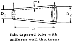
|
$$ \theta = { 2 T L (D_1 + D_2) \over \pi G t D_1^2 D_2^2 } $$ |
1.5.1.3 Sample Problem - Circular Beams in Torsion
Given: The circular beam shown in Figure 1-48.

Find: The angle of twist and maximum stress in the beam.
Solution: From Table 1-13.
Applying Equation (1-47) to the outside of the thin end of the beam
Need a Beam Calculator?
Try this beam calculator.
- Calculates stresses and deflections in straight beams
- Builds shear and moment diagrams
- Can specify any configuration of constraints, concentrated forces, and distributed forces
1.5.2 Noncircular Beams in Torsion
In the derivation of formulas for circular beams in torsion, it was assumed that plane sections remain plane and radii remain straight in the deformed configuration. Since these assumptions no longer hold for noncircular sections, the equations for circular sections do not hold. The warping of plane sections of a square bar under torsion is illustrated in Figure 1-49.

In this section, open beams are treated first and closed beams are treated second. Closed beams are those with hollow sections, and other beams are called open beams. Since plane sections remain plane for round beams in torsion, the end constraint of such a beam does not effect its behavior. However, end constraint can be an important factor in the treatment of noncircular beams in torsion and is treated in Section 1.5.3.3. At a sufficient distance from the application of the load, however, the stresses depend only on the magnitude of the applied torque according to Saint-Venant's principle.
1.5.2.1 Noncircular Open Beams in Torsion
This section deals with noncircular beams whose cross sections are not hollow. Section 1.5.2.1.1 gives the stress distribution in elliptical beams in torsion, and Section 1.5.2.1.2 treats beams with rectangular cross sections. Section 1.5.2.1.3 treats open noncircular beams with thin sections with formulas for thin rectangular sections. Table 1-15 in Section 1.5.2.1.5 gives formulas for stress and deformation in noncircular beams with various sections.
All of the material in this section is based upon the assumption that cross sections are free to warp.
1.5.2.1.1 Elliptical Beams in Torsion
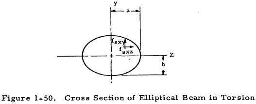
Figure 1-50 shows a cross section of an elliptical beam in torsion and the two components of shear stress that are present. The shear stress components shown are given by
and
where T is the torque applied to the beam. The maximum shear stress occurs at (z = 0, y = b) and is given by
The angle of twist of an elliptical beam of length, L, is
1.5.2.1.2 Rectangular Beams in Torsion
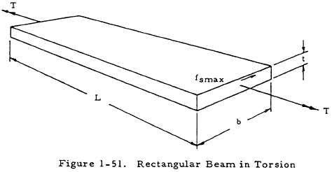
Figure 1-51 shows a rectangular beam in torsion. The maximum stress in such a beam occurs at the center of the long side and is given by
where α is a constant given in Table 1-14. The angle of twist of a rectangular beam in torsion is
where β is given in Table 1-14.
| b/t | 1.00 | 1.50 | 1.75 | 2.00 | 2.50 | 3.00 | 4 | 6 | 8 | 10 | ∞ |
| α | 0.208 | 0.231 | 0.239 | 0.246 | 0.258 | 0.267 | 0.282 | 0.299 | 0.307 | 0.313 | 0.333 |
| β | 0.141 | 0.196 | 0.214 | 0.229 | 0.249 | 0.263 | 0.281 | 0.299 | 0.307 | 0.313 | 0.333 |
The maximum stress and angle of twist of a rectangular beam in torsion may also be computed with satisfactory accuracy (error less than 4%) from the following equations:
1.5.2.1.3 Noncircular Beams with Thin Open Sections in Torsion
If a rectangular beam is very thin relative to its length (b ≫ t) Equations (1-59) and (1-60) become
and
From Table 1-14, it can be seen that these expressions are correct within 10 percent if b/t = 8.
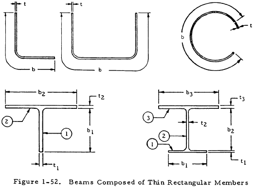
Although Equations (1-61) and (1-62) have been developed for rectangular beams, they can be applied to the approximate analysis of shapes made up of thin rectangular members such as those in Figure 1-52. If sharp corners exist, however, large stress concentrations may result so that Equation (1-61) is not valid. The effect of sharp corners is explained by the membrane analogy in Section 1.5.3.1. Equations (1-61) and (1-62) may be applied directly to sections such as those at the top of Figure 1-52 if b is taken to be the developed length of the cross section as shown.
If a thin section is composed of a number of thin rectangular sections as are those at the bottom of Figure 1-52, the following equations may be applied:
In the above equations, fmax.n is the maximum stress in the nth rectangular portion of the section, L is the beam length, and T is the applied torque.
If a section is composed of thick rectangular sections, the equations in Section 1.5.2.1.5 should be used. The advantage of the equations in this section is that they may be applied to specific shapes for which a more exact formula may not be available.
1.5.2.1.4 Sample Problem - Noncircular Beams with Thin Open Sections in Torsion
Given: A 50-in.-long beam with a cross section such as that shown in Figure 1-53 under a torsional load of 500 in-lb.
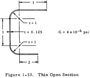
Find: The maximum shear stress and the angle of twist of the beam.
Solution: The developed length of the section is
$$ b = 3 + 3 + 2 + \pi = 11.14 ~\text{in} $$Equations (1-61) and (1-62) may now be applied to obtain
and
1.5.2.1.5 Noncircular Open Beams with Various Cross Sections in Torsion
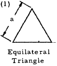
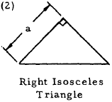
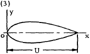
Table 1-15 gives formulas for the deformation and stress of open noncircular beams with various cross sections in torsion. The formulas for Case 1 are based on rigorous mathematical analysis, and the remaining formulas are obtained either by approximate mathematical analysis or the membrane analogy and are normally accurate within 10 percent.
| Form of Cross Section | Angle of Twist | Magnitude and Location of Maximum Shear Stress |
|---|---|---|
|
$$ \theta = { 80 ~TL \over 3 ~G a^4 } $$ | $$ f_{smax} = { 20 ~T \over a^3 } $$ at the midpoint of each side |
|
$$ \theta = { 38.31 ~TL \over ~G a^4 } $$ | $$ f_{smax} = { 18.05 ~T \over a^3 } $$ |
|
$$ \theta = { TL \left( 1 + { 16 I_x \over A U^2 } \right) \over 4 ~I_x ~G } $$
|
For cases (3) to (9) inclusive, \(f_{smax}\) occurs at or very near one of the points where the largest inscribed circle touches the boundary, unless there is a sharp reentrant angle at some other point on the boundary causing high local stress. Of the points where the largest inscribed circle touches the boundary, \(f_{smax}\) occurs at the one where the boundary curvature is algebraically least. (Convexity represents positive, concavity negative, curvature of the boundary. At a point where the curvature is positive (boundary of section straight or convex) the maximum stress is given approximately by $$ f_{smax} = { G \theta c \over L } $$where
$$
\begin{eqnarray}
c &=& { D \over 1 + { \pi^2 D^4 \over 16 A^4 } } ~ \bigg[ 1 + \nonumber \\
&~& 0.15 \left( {\pi^2 D^4 \over 16 A^2} - { D \over 2r } \right) \bigg]
\end{eqnarray}
$$
where \(D =\) diameter of largest inscribed circle \(r =\) radius of curvature of boundary at the point (positive for this case) \(A =\) area of the section At points where the boundary of a section is concave or reentrant, the maximum stress is given approximately by $$ f_{smax} = { G \theta c \over L } $$where
$$
\begin{eqnarray}
c &=& { D \over 1 + { \pi^2 D^4 \over 16 A^4 } } ~ \Bigg[ 1 + \bigg\{ 0.118 ~\ln{\left( 1 - { D \over 2r } \right)} \nonumber \\
&-& { 0.238 ~D \over 2r } \bigg\} ~\tanh{ 2 \phi \over r } \Bigg]
\end{eqnarray}
$$
where \(D\), \(A\) and \(r\) have the same meaning as before and \(\phi\) = angle through which a tangent to the boundary rotates in turning or traveling around the reentrant portion, measured in radians. (Here \(r\) is negative.) |

Any elongated section or thin tube. \(dU =\) elementary length along median line \(t =\) thickness normal to median line \(A =\) area of section |
$$ \theta = { 3 \left( 1 + { 4 F \over 3 A U^2 } \right) TL \over G F } $$
where $$ F = \int_0^U t^3 dU $$ |
|

Any solid, fairly compact section without reentrant angles. \(I_p =\) polar moment of inertia about centroidal axis \(A =\) area of the section |
$$ \theta = { 40 ~T L I_p \over G A^4 } $$ | |
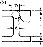
I section, flange thickness. \(r =\) fillet radius \(D =\) diameter of largest inscribed circle \(t = b\) if \(b \lt d\), \(t = d\) if \(d \lt b\), \(t_1 = b\) if \(b > d\), \(t_1 = d\) if \(d > b\) |
$$ \theta = { TL \over G ( 2K_1 + K_2 + 2 a D^4 ) } $$
where
$$ K_1 = ab^3 \left[ {1 \over 3} - 0.21 {b \over a} \left( 1 - { b^4 \over 12 a^4 } \right) \right] $$
$$ K_2 = {1 \over 3} c d^3 $$
and
$$ a = {t \over t_1} \left( 0.15 + 0.1 {r \over b} \right) $$
|
|
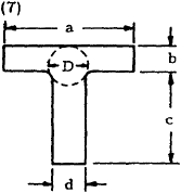
T section, flange thickness uniform: \(r\), \(D\), \(t\) and \(t_1\) as for Case (6). |
$$ \theta = { TL \over G ( K_1 + K_2 + \alpha D^4 ) } $$
where
$$ K_1 = ab^3 \left[ {1 \over 3} - 0.21 {b \over a} \left( 1 - { b^4 \over 12 a^4 } \right) \right] $$
$$ K_2 = cd^3 \left[ {1 \over 3} - 0.105 {d \over c} \left( 1 - { d^4 \over 192 c^4 } \right) \right] $$
and
$$ \alpha = {t \over t_1} \left( 0.15 + 0.1 {r \over b} \right) $$
|
|
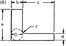
L section \(r\) and \(D\) as for Cases (6) and (7) |
$$ \theta = { TL \over G ( K_1 + K_2 + \alpha D^4 ) } $$
where
$$ K_1 = ab^3 \left[ {1 \over 3} - 0.21 {b \over a} \left( 1 - { b^4 \over 12 a^4 } \right) \right] $$
$$ K_2 = cd^3 \left[ {1 \over 3} - 0.105 {d \over c} \left( 1 - { d^4 \over 192 c^4 } \right) \right] $$
and
$$ \alpha = {d \over b} \left( 0.07 + 0.076 {r \over b} \right) $$
|
|

|
$$ \theta = { TL \over G ~\sum ( K_1 + K_2 + \alpha D^4 ) } $$
where the summation is for the constituent L sections computed as for case (8) |
Need a Beam Calculator?
Try this beam calculator.
- Calculates stresses and deflections in straight beams
- Builds shear and moment diagrams
- Can specify any configuration of constraints, concentrated forces, and distributed forces
1.5.2.2 Noncircular Closed Beams in Torsion
Closed beams have one or a number of hollow portions in their cross section. This type of beam is much more efficient in torsion than open beams.
Section 1.5.2.2.1 treats single cell closed or box beams in torsion, and Section 1.5.2.2.7 treats multicell closed beams in torsion.
1.5.2.2.1 Single Cell Noncircular Closed Beams in Torsion
This section treats box beams with a single hollow portion in their cross section. Section 1.5.2.2.2 treats such beams having uniform cross section, and Section 1.5.2.2.3 treats tapered box beams. The effect of stiffeners and cutouts in box beams are treated in Sections 1.5.2.2.4 and 1.5.2.2.6, respectively.
1.5.2.2.2 Single Cell Noncircular Closed Beams with Uniform Cross Section in Torsion
Figure 1-54 shows a cross section of a thin box beam. The angle of twist of such a beam of length, L, due to an applied torque, T, is given by
In this equation, A is the area enclosed by the median line, t is the thickness at any point, and U is the length along the median line. The shear flow in such a tube is uniform at all points and is given by
If the shear stress is assumed to be uniform across any thickness, it is given by
From this expression, it can be seen that the maximum shear stress occurs where the thickness is minimum.
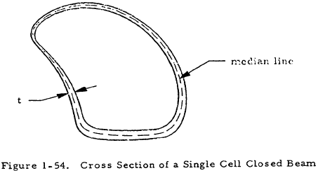
If the thickness of the tube is uniform, Equation (1-67) becomes
and Equations (1-68) and (1-69) remain the same.
1.5.2.2.3 Single Cell Noncircular Tapered Closed Beams in Torsion
Figure 1-55 shows a tapered box beam under a torsional load, T. Since all four sides are tapered in such a way that the corners of the box would intersect if extended, the equations in Section 1.5.2.2.2 may be applied to this beam if A is taken to be the area at the cross section in question.

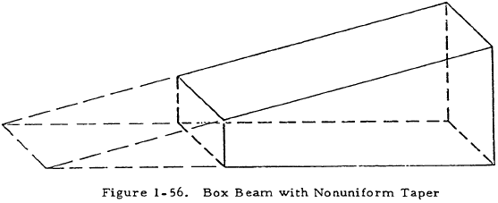
However, these equations no longer apply for box beams for which the taper ratio of the horizontal webs is not the same as that of the vertical webs since the shear flows will not have the same distribution for all webs. Such a beam is shown in Figure 1-56. Although the equations in Section 1.5.2.2.2 are not valid for a box beam such as that shown in Figure 1-56, they are quite accurate for the common airplane wing structure with closely spaced ribs. The ribs divide the web into several smaller webs and serve to distribute shear flows so that they are approximately equal in the horizontal and vertical webs.
1.5.2.2.4 Effect of Stiffeners on Noncircular Closed Beams in Torsion
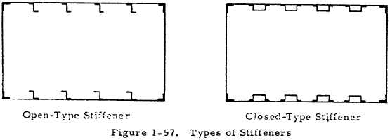
Thin-walled airplane structures usually contain longitudinal stiffeners spaced around the outer walls as shown in Figure 1-57. If the open-type stiffener, as shown to the left in Figure 1-57, is used, the torsional rigidity of the individual stiffeners is so small compared to the torsional rigidity of the thin-walled cell that it is negligible. However, a closed-type stiffener is essentially a small tube and its stiffness is thus much greater than that of an open section of the same size. Thus, a cell with closed-type stiffeners attached to its outer walls could be treated as a multicell closed beam with each stiffener forming an additional cell. Since the analysis of a beam with a large number of cells is difficult and, in general, the torsional stiffness provided by the stiffeners is small compared to that of the overall cell, an approximate simplified procedure may be used with sufficient accuracy.
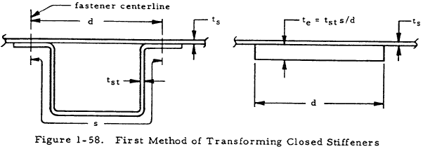
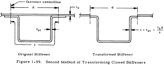
In the approximate method, the thin-walled tube and closed stiffeners are converted into an equivalent single thin-walled tube by modifying the closed stiffeners by one of two procedures. This equivalent tube is then analyzed according to the material in Section 1.5.2.2.2. The two procedures for modifying the closed stiffeners are:
-
Replace each closed stiffener by a doubler plate having an effective thickness given by
$$ t_e = t_{st} ~s / d $$This procedure and the necessary nomenclature are illustrated in Figure 1-58.(1-71)
-
Replace the skin over each stiffener by a "liner" having a thickness given by
$$ t_e = t_s ~d / s $$This method and the necessary nomenclature are illustrated in Figure 1-59. The first of these procedures slightly overestimates the stiffness effect of the stiffeners, whereas the second procedure slightly underestimates this effect.(1-72)
Since the corner members of a stiffened cell are usually open or solid sections such as those shown in Figure 1-57, their torsional resistance can be simply added to the torsional stiffness of the thin-walled overall cell.
1.5.2.2.5 Sample Problem - Noncircular Closed Stiffened Uniform Section Beam in Torsion
Given: A 120-in. -long beam under an applied torque of 10,000 in. lb. with a cross section as shown in Figure 1-60.
Find: The angle of twist and maximum shear stress in the beam.
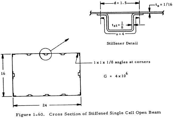
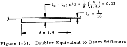
Solution: From Section 1.5.2.2.4, a doubler plate equivalent to a stiffener may be drawn as shown in Figure 1-61. The area enclosed by the median line of the transformed section is thus
$$ A = (24 \times 16) - 8 \left({t_e \over 2}\right) (d) - 4 \left({ 1 \over 16 }\right) (2) $$where the last term takes into account the effect of the corner angles. Thus,
Applying Equation (1-67) to the equivalent beam gives
where the terms in the parenthesis represent integration over the doubler, angles and skin, respectively. Thus
From Equation (1-69)
$$ f_s = { T \over 2 A t } = { 10^4 \over 2 (381.5) t } = { 13.1 \over t } $$Thus, the maximum shear stress occurs at the point of minimum thickness and
$$ f_s = { 13.1 \over 0.0625 } = 210 ~\text{psi} $$1.5.2.2.6 Effect of Cutouts on Closed Single Cell Beams in Torsion
Typical aircraft structures consist of closed boxes with longitudinal stiffeners and transverse bulkheads. It is necessary to provide many openings in the ideal continuous structure for wheel wells, armament installations, doors, windows, etc. These cutouts are undesirable from a structural standpoint but are always necessary. A closed torque box is necessary for most of the span of an airplane wing but may be omitted for a short length such as the length of a wheel well opening. When a portion of the skin is omitted for such a region, the torsion is resisted by differential bending of the spars, as indicated in Figure 1-62, since the open section has low torsional rigidity. If the torsion is to be assumed to be resisted by the two side webs acting independently as cantilever beams, as shown in Figure 1-62(b), one end must be built in as shown in Figure 1-62(a).
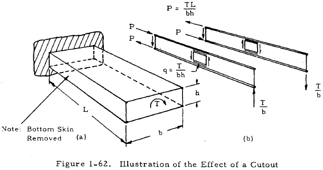
The existence of a cutout and the resultant axial loads in the flanges also increase the shear now in closed portions of the box adjacent to the cutouts.
1.5.2.2.7 Multicell Closed Beams in Torsion
Figure 1-63 shows the internal shear flow pattern on a multicell tube consisting of n cells under a pure torsional load, T. The torque applied to this tube is given by
where A1 through An are the areas enclosed by the medium lines of cells 1 through n. The line integral, ∫ds/t, where s is the length of the median of a wall and t is the wall thickness, may be represented by a. Then aKL is the value of this integral along the wall between cells K and L, where the area outside the tube is designated as cell (0). Using this notation, the following equations may be written for cells (1) through (n):
The shear flows, q1 through qn may be found by solving Equations (1-73) through (1-78) simultaneously. From these shear flows, the shear stress distribution may be found since fs = q/t.

1.5.2.2.8 Sample Problem- Multicell Closed Beams in Torsion
Given: A multicell beam with the cross section shown in Figure 1-64 under a torsional load of 5,000 in. lb.
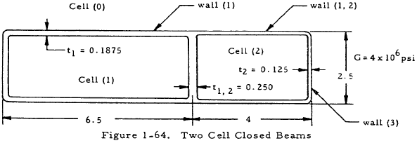
Find: The shear stress in each of the walls.
Solution: Assuming the cell corners to square gives
$$ A_1 = (2.5) (6.5) = 16.25 ~\text{in}^2 $$ $$ A_2 = (2.5) (4) = 10 ~\text{in}^2 $$ $$ a_{10} = [2(6.5) + 2.5] / 0.1875 = 77.3 $$ $$ a_{12} = 2.5/0.250 = 10 $$ $$ a_{20} = [2(4) + 2.5] / 0.125 = 84 $$Applying Equations (1-73), (1-74), and (1-75) to the given beam gives
$$ T = 2 q_1 A_1 + 2 q_2 A_2 $$ $$ {1 \over A_1} [ q_1 a_{10} + (q_1 - q_2) a_{12} ] = 2 G \theta $$and
$$ {1 \over A_2} [ (q_2 - q_1) a_{12} + q_2 a_{20} ] = 2 G \theta $$Inserting numerical values into these equations gives
$$ 5000 = 2 q_1 (16.25) + 2 q_2 (10) $$and
$$ {1 \over 10} [ (q_2 - q_1) (10) + q_2 (84) ] = 2 (4 \times 10^6) \theta $$Solving these equations simultaneously gives
$$ q_1 = 78 ~\text{lb/in} $$ $$ q_2 = 123 ~\text{lb/in} $$ $$ \theta = 1.345 \times 10^{-4} ~\text{rad} = 0.0077^{\circ} $$The shear stress in wall (1) is
$$ f_s = {q_1 \over t_1} = {78 \over 0.1875} = 415 ~\text{psi} $$The shear stress in wall (2) is
$$ f_s = {q_2 \over t_2} = {123 \over 0.125} = 984 ~\text{psi} $$The shear stress in wall (1,2) is
$$ f_s = { q_1 - q_2 \over t_{1,2} } = { 123 - 78 \over 0.250 } = 180 ~\text{psi} $$1.5.2.3 Effect of End Restraint on Noncircular Beams in Torsion
The equations for noncircular beams in torsion in previous sections assumed that cross sections throughout the length of torsion members were free to warp out of their plane and thus there could be no stresses normal to the cross sections. In actual structures, restraint against the free warping of sections is often present at the point of attachment of a beam. For example, the airplane wing cantilevers from its attachment to a rather rigid fuselage structure and is restrained against warping at its point of attachment. The effect of end restraint is greater at points close to the restraint than those further removed. Sections such as I-beams are more affected by end restraint than compact sections such as circles and squares.
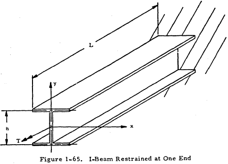
Figure 1-65 shows an I-beam with one end restrained under a torsional load, T. The maximum flange bending moment is
where
and θ is the angle of twist of an I-beam with unrestrained ends given in Table 1-15. The angle of twist of such an I-beam with restrained ends is
From this equation, it can be seen that the end restraint has a stiffening effect on the beam.
Need a Beam Calculator?
Try this beam calculator.
- Calculates stresses and deflections in straight beams
- Builds shear and moment diagrams
- Can specify any configuration of constraints, concentrated forces, and distributed forces
1.5.3 Analogies for Beams in Torsion
Two analogies for beams in torsion are useful both for visualization of stress distributions and magnitudes and for experimental work. The membrane analogy, which is described in Section 1.5.3.1, is valid for open beams for which the shear stress is in the elastic range. The sand heap analogy (Section 1.5.3.2) may be used to treat open beams under torsional loads for which the plastic shear stress is the same at all points on the cross section.
1.5.3.1 Membrane Analogy for Beams in Elastic Torsion
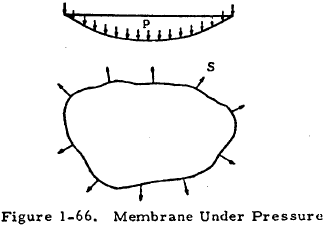
The equation for the torsion of a beam in the elastic range is analogous to that for small deflections of a membrane under uniform pressure. Figure 1-66 shows such a membrane. The pressure on the membrane is designated as p, and S is the uniform tension per unit at its boundary. The membrane analogy gives the following relationships between the deflected membrane and a beam of the same cross section in torsion:
- Lines of equal deflection on the membrane (contour lines) correspond to shearing stress lines of the twisted bar.
- The tangent to a contour line at any point on the membrane surface gives the direction of the resultant shear stress at the corresponding point on the cross section of the bar being twisted.
- The maximum slope of the deflected membrane at any point with respect to the edge support plane is proportional to the shear stress at the corresponding point on the cross section of the twisted bar. Thus, the shear stress is greatest where the contour lines are closest.
- The applied torsion on the twisted bar is proportional to twice the volume included between the deflected membrane and a plane through the supporting edges. If p/S = 2Gθ, this torque is equal to twice the volume.
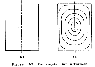
The membrane analogy may be used to experimentaliy measure quantities for beams in torsion. However, possibly the main advantage of the membrane theory is that it provides a method of visualizing to a considerable degree of accuracy how stress conditions vary over a complicated cross section of a beam in torsion. For example, consider the bar with rectangular cross section shown in Figure 1-67(a). A membrane may be stretched over an opening of the same shape and deflected by a uniform pressure. Equal deflection lines for the deflected membrane will take the shape as shown in Figure 1-67(b). These contour lines tend to take the shape of the bar boundary as it is approached as does the direction of shearing stress. The shear stress is maximum where the contour lines are closest (center of long side). Since the applied torsion is proportional to the membrane volume, the more elongated of two rectangular bars of equal area has the smaller torsional rigidity. Also, it is obvious that bending a long thin rectangular section will not appreciably change the membrane volume and, thus, the torsional rigidity of a bar of this shape.
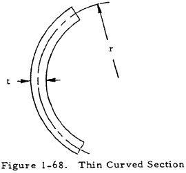
The membrane analogy also makes it apparent that stresses are very low at the ends of outstanding flanges or protruding corners and very high where the boundary is sharply concave. For example, Table 1-16 gives the stress concentration factor for the concave side of the shape in Figure 1-68. Multiplying the maximum stress obtained from the formula for thin rectangular sections in torsion by this factor gives the maximum stress on the concave side of a thin bent section.
| r/t | 1/8 | 1/4 | 1/2 | 1 |
| Factor | 2-1/2 | 2-1/4 | 2 | 1-3/4 |
1.5.3.2 Sand Heap Analogy for Beams in Plastic Torsion
The maximum ultimate torque that an open beam may withstand in torsion is given by
where V is the volume of a sand heap with a maximum slope of unity, piled on a plate having the same shape as the beam cross section. Table 1-17 gives the volume of sand heaps with various bases of various shapes.
| Type of Section | Sand Heap Volume |
|---|---|
|
Rectangle 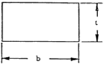
|
$$ V = { t^3 (3b - t) \over 12 }, ~ b \ge t $$ |
|
Circle 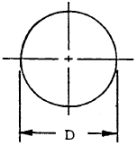
|
$$ V = { \pi D^3 \over 24 } $$ |
|
Triangle 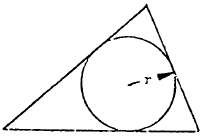
A = area of triangle r = radius of inscribed circle |
$$ V = { A r \over 3 } $$ |
