Simple Thin Pressure Vessels
This page provides the sections on the analysis of simple thin pressure vessels from the "Stress Analysis Manual," Air Force Flight Dynamics Laboratory, October 1986.
Other related chapters from the Air Force "Stress Analysis Manual" can be seen to the right.
- Simple Thin Pressure Vessels
- Stiffened Thin Pressure Vessels
- Thick Pressure Vessels
- Anisotropic Pressure Vessels
8.1 Introduction to Pressure Vessels
For purposes of analysis, pressure vessels may be divided into two classes, thick and thin. Thin pressure vessels are those for which the ratio of the least radius of curvature of the wall to its thickness is greater than ten. These thin pressure vessels are further subdivided into simple ones which are discussed in Section 8.3.1 and stiffened ones which are discussed in Section 8.3.2. Thick pressure vessels are discussed in Section 8.4. Section 8.5 gives a brief discussion of anisotropic pressure vessels and in particular glass filament vessels.
8.2 Nomenclature for Simple Thin Pressure Vessels
| A | = | cross-sectional area |
| a | = | one-half the major diameter of semielliptical head |
| b | = | one-half the minor diameter of semielliptical head |
| b | = | subscript, bending |
| Cn | = | constant |
| c | = | subscript, compressive |
| co | = | subscript, crippling |
| cr | = | subscript, critical |
| d | = | mean diameter |
| di | = | inside diameter |
| do | = | outside diameter |
| E | = | modulus of elasticity |
| Es | = | secant modulus of elasticity |
| Et | = | tangent modulus of elasticity |
| Fbmer | = | meridional bending stress |
| Fbs | = | bending stress in skin |
| Fbt | = | circumferential bending stress |
| Fcc | = | crippling stress of unpressurized cylinder |
| Fccp | = | crippling stress of pressurized cylinder |
| Fcp | = | proportional limit in compression |
| Fcr | = | critical stress |
| Fcy | = | compressive yield stress |
| Fmax | = | maximum stress |
| Fmer | = | meridional or axial stress |
| Fmermax | = | maximum meridional stress |
| Fmmer | = | meridional membrane stress |
| Fmt | = | circumferential membrane stress |
| Fr | = | radial stress |
| Frmax | = | maximum radial stress |
| Fscc | = | crippling shear stress of unpressurized cylinder |
| Fsccp | = | crippling shear stress of pressurized cylinder |
| Fsmax | = | maximum shear stress |
| Fsmer | = | meridional shear stress |
| Ft | = | tangential or circumferential stress |
| Ftmax | = | maximum circumferential stress |
| fs | = | calculated shear stress |
| I | = | moment of inertia |
| Imer | = | stress ratio = \( { F_{mermax} \over pd/2t } \) |
| Ip | = | polar moment of inertia |
| Is | = | stress ratio = \( { F_{smax} \over pd/2t } \) |
| It | = | stress ratio = \( { F_{tmax} \over pd/2t } \) |
| i | = | subscript, inside |
| kp | = | buckling coefficient for sphere |
| ky | = | buckling coefficient for cylinder |
| L | = | cylinder length |
| M | = | bending moment |
| Mcr | = | critical bending moment |
| Mo | = | discontinuity moment |
| m | = | subscript, membrane |
| m | = | subscript, midspan |
| mer | = | subscript, meridional |
| Nmmer | = | meridional membrane stress times wall thickness (Fmmer t) |
| Nmt | = | tangential membrane stress times wall thickness (Fmt t) |
| n | = | distance from midplane of flat head to joint divided by head thickness |
| o | = | subscript, outside |
| P | = | axial load |
| P | = | reaction force |
| p | = | pressure difference (pi − po) |
| p | = | subscript, polar |
| p | = | subscript, pressurized |
| pi | = | internal pressure |
| po | = | external pressure |
| Qo | = | discontinuity force |
| R | = | radius curvature |
| R | = | radius to centroid of minimum area of ring |
| Rb | = | applied bending moment / critical bending moment |
| Rc | = | applied compressive load / critical compressive load |
| Rmer | = | meridional radius of curvature |
| Rs | = | applied transverse shear load divided by critical transverse shear load |
| Rst | = | applied torsional moment divided by critical torsional moment |
| Rt | = | tangential or circumferential radius of curvature |
| r | = | mean radius |
| r | = | radius to the inside of the skin of stiffened cylinder |
| r | = | cylindrical or polar coordinate |
| r | = | subscript, radial |
| r | = | subscript, ring |
| ri | = | inside radius of dished head |
| rk | = | knuckle radius in dished head |
| s | = | subscript, shear |
| s | = | subscript, skin |
| st | = | subscript, stringer |
| T | = | head thickness |
| T | = | torque |
| t | = | wall thickness |
| t | = | subscript, tangential or circumferential |
| tr | = | thickness of flange attachment to skin |
| w1 | = | radial deflection of head due to Qo and Mo |
| w2 | = | radial deflection of cylinder due to Qo and Mo |
| wm1 | = | radial deflection of head due to internal pressure |
| wm2 | = | radial deflection of cylinder due to internal pressure |
| y | = | subscript, yield |
| x, y, z | = | rectangular coordinates |
| α | = | half the apex angle of a cone |
| β | = | angle of contact of saddle support |
| Δ | = | increment or difference |
| Δn | = | parameter in Figures 8-45 through 8-49 |
| δ | = | radial deflection of shell |
| δm | = | radial deflection of shell midway between rings |
| δr | = | radial deflection of shell at ring |
| η | = | plasticity reduction factor |
| θ1 | = | angular rotation of head due to Qo and Mo |
| θ2 | = | angular rotation of cylinder due to Qo and Mo |
| λ1 | = | \( \sqrt[\uproot{1} \scriptstyle 4]{ 3 (1 - \mu^2) / r^2 T^2 } \) |
| λ2 | = | \( \sqrt[\uproot{1} \scriptstyle 4]{ 3 (1 - \mu^2) / r^2 t^2 } \) |
| μ | = | Poisson's ratio |
| μe | = | elastic Poisson's ratio \( \left[ \mu_p \left( {E_s \over E} - 1 \right) + \mu \right] { E \over E_s } \) |
| μp | = | plastic Poisson's ratio (generally 0.5) |
| Ωn | = | parameter in Figures 8-41 through 8-44 |
| ϕo | = | angle between cylinder axis and normal to head at head-cylinder junction |
8.3 Thin Pressure Vessels
This section deals with pressure vessels for which the ratio of minimum radius of curvature of the wall to its thickness is greater than ten. These thin pressure vessels are further subdivided for purposes of discussion into simple and stiffened pressure vessels. A simple pressure vessel is defined here as one that does not have stiffeners while a stiffened one may have rings and/or stringers stiffening its walls.
8.3.1 Simple Thin Pressure Vessels
This class of pressure vessel includes unstiffened vessels for which the ratio of the minimum radius of curvature of the wall to its thickness is greater than ten.
Membrane stresses in simple thin pressure vessels are considered first here and then the problem of discontinuity stresses at the junction of a cylinder and its head is considered. The material in these first sections is based on the assumption that failure by buckling under external pressures does not occur. The possibility of buckling is treated in Section 8.3.1.3. The previously mentioned sections cover stresses due to pressure loads alone. Section 8.3.1.4 deals with stresses due to external loads from support, and Section 8.3.1.5 treats of the effect of internal pressure upon the crippling stress of thin cylinders under various loads.
We have a number of structural calculators to choose from. Here are just a few:
8.3.1.1 Membrane Stresses in Simple Thin Shells of Revolution
In a thin pressure vessel, no stresses other than those tangential to the surface are present at points sufficiently removed from discontinuities in the curvature, slope, or thickness of the wall. These tangential or membrane stresses are constant throughout the thickness of the shell. At points near discontinuities, such as the junction of a cylinder and its head discontinuity, stresses must be superposed upon the membrane stresses in order to obtain the total stress. These discontinuity stresses are discussed in Section 8.3.1.2.2.
In the following discussion, the difference between internal and external pressure (pi − po) is assumed to be uniform over the surface.
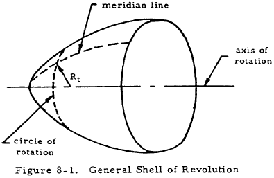
Figure 8-1 shows a general thin shell of revolution. The meridian lines of this shell are defined by the intersection of the shell and a plane passing through the axis of rotation of the surface. The circles of rotation are the intersection of the shell with planes perpendicular to the axis of rotation.
The two basic equations for a thin shell of revolution are
and
In these equations, Rmer is the radius of curvature of a meridian line and R is the distance from the shell to its axis of rotation along a normal to the shell. Both of these radii are taken to a surface located midway between the inside and outside surfaces of the shell. Nmmer is the stress in the direction of the meridian line times the shell thickness and Nmt is the stress in the direction of a circle of rotation times the shell thickness.
8.3.1.1.1 Membrane Stresses in Thin Cylinders
Figure 8-2 shows a thin cylindrical shell (R/t > 10).

Since the meridian lines are straight, Rt, which is their radius of curvature, is equal to infinity. Similarly,Rmer may be found to be equal to r by applying its definition. Inserting these values into Equations (8-1) and (8-2) and solving gives
and
Since Nmt = Fmt t and Nmmer = Fmmer t,
and
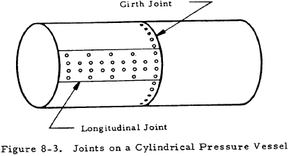
From these equations, it can be seen that the ratio of the longitudinal to the circumferential stress, Fmmer/Fmt is equal to 0.5. Thus, the strength of a girth joint may be as low as one-half that of a longitudinal joint as is illustrated in Figure 8-3.
8.3.1.1.2 Membrane Stresses in Thin Spheres
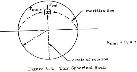
Figure 8-4 shows a thin spherical shell (r/t > 10). Applying Equations (8-1) and (8-2) to the shape in Figure 8-4 gives
Thus,
8.3.1.1.3 Sample Problem - Membrane Stresses in Thin Cylinders and Spheres
Given: The cylindrical pressure vessel shown in Figure 8-5.
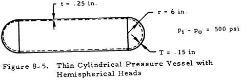
Find: The membrane stresses in the cylinder and the heads.
Solution: Applying Equations (8-5) and (8-6) to the cylindrical portion gives
$$ F_{mt} = { 500 (6) \over 0.25 } = 12,000 ~\text{psi} $$and
$$ F_{mmer} = { 500 (6) \over 2 (0.25) } = 6,000 ~\text{psi} $$Applying Equation (8-8) to the hemispherical heads gives
$$ F_{mt} = F_{mmer} = { 500 (6) \over 2 (0.15) } = 10,000 ~\text{psi} $$It should be noted that the discontinuity stresses at the head-cylinder junction may be much greater than these membrane stresses.
We have a number of structural calculators to choose from. Here are just a few:
8.3.1.2 Heads of Thin Cylindrical Pressure Vessels
In the previous discussion, membrane stresses in thin pressure vessels, the slope, curvature, and direction of the meridian lines as well as wall thickness were assumed to be continuous. However, one or more of these assumptions do not hold true at the connection between a cylindrical pressure vessel and any of the types of heads used in practice.
The tendency of the head of a cylindrical pressure vessel to deform radially and angularly at a different rate than the cylindrical portion, combined with the requirement of geometric compatibility, necessitates certain discontinuity stresses near the head joint. Thus, unconservative designs will be obtained if the membrane stresses are the only ones considered. These discontinuity stresses are discussed more fully in Section 8.3.1.2.2.
By proper design of a pressure vessel, the discontinuity stresses may be greatly reduced so that localized yielding will level out any stress peaks and these stresses need not be considered for static strength analysis. In the A.S.M.E. code for unfired pressure vessels, formulas for the thickness of shells and heads (except in the case of flat heads) consider membrane stresses only. But the proper design to prevent excessive discontinuity stresses is specified. For example, proper design of a dished head requires that the inequalities shown in Figure 8-6 be satisfied.
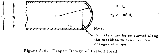
Formulas for membrane stresses in several types of thin heads are given in Section 8.3.1.2.1.
If a pressure vessel is subjected to repeated loadings where fatigue is considered likely, stress peaks due to discontinuity stresses are of great importance since localized yielding is no longer beneficial.
8.3.1.2.1 Membrane Stresses in Heads of Thin Cylindrical Pressure Vessels
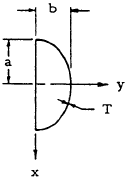
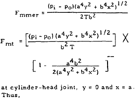
Formulas may be found for membrane stresses in several common types of heads by the use of Equations(8-1) and (8-2). These are listed in Table 8-1.
| Type of Head | Membrane Stresses | |
|---|---|---|
| hemispherical or dished |

|
$$ F_{mmer} = F_{mt} = { (p_i - p_o) ~r \over 2T } $$
|
| semielliptical |
|
$$ F_{mmer} = { (p_i - p_o) a \over 2 T } $$
$$ F_{mt} = { p a \over t } \left( 1 - { a^2 \over 2 b^2 } \right) $$
|
| conical |

|
$$ F_{mmer} = { (p_i - p_o) d \over 4 T \cos{ \alpha } } $$
$$ F_{mt} = { (p_i - p_o) d \over 2 T \cos{ \alpha } } $$
|
It can be seen from the equation for Fmt at x = a for an elliptical head that this hoop stress is compressive if a is greater than √2 b. Thus, the displacement of the edge would actually be inward in this case. This is an undesirable situation because of a possibility of high discontinuity stresses.
Wherever discontinuity stresses cannot be ignored, they may be superposed upon the membrane stresses. Discontinuity stresses are discussed in the following section.
8.3.1.2.2 Discontinuity Stresses at the Junction of a Thin Cylindrical Pressure Vessel and Its Head
8.3.1.2.2.1 Introduction to Discontinuity Stresses
If there is an abrupt change in the thickness or in the meridional slope or curvature at any circumference of a thin vessel, bending stresses occur in addition to the membrane stresses. These "discontinuity stresses" are of four types:
- a meridional bending stress, Fbmer, which varies linearly throughout the thickness of the wall,
- a circumferential or hoop bending stress, Fbt, which varies linearly throughout the thickness of the wall,
- an additional hoop stress, Ft, uniform throughout the thickness of the wall, and
- a meridional shear stress, Fsmer, assumed uniform throughout the thickness of the wall.
In order to determine the state of stress of a pressure vessel, it is necessary to find membrane stresses and discontinuity stresses. The total stresses may be obtained from the superposition of these two states of stress.
8.3.1.2.2.2 Discontinuity Stresses at Junction of Thin Cylindrical Pressure Vessel and Head
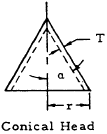
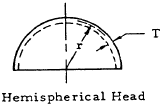
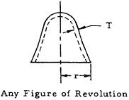
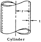
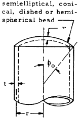
If a cylindrical pressure vessel is subjected to pressure, the cylindrical part and its head will tend to expand at different rates as shown in Figure 8-7. The head alone would displace radially a distance wm1 because of internal pressure, and the cylindrical portion would displace wm2 if it were not attached to the head. However, geometric compatibility requires the head and cylinder to displace equal amounts. Thus, the force Qo and the moment Mo must exist between the head and the cylinder to hold them together. These, in turn, cause discontinuity stresses near the junction between the cylinder and its head.
The following procedure may be used to solve for discontinuity stresses. First, the difference in radial displacements due to Qo and Mo must cancel the difference in radial displacements due to internal pressure. That is,
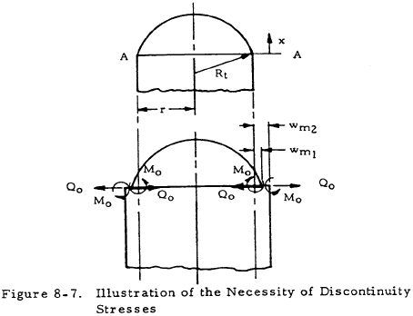
The values of wm1 and wm2 as functions of pressure may be obtained in Table 8-2 for various head shapes, and values for w1 and w2 as functions of Qo and Mo may be obtained from Table 8-3. The angles of rotation of the cylinder and head edges due to Qo and Mo must be equal. That is,
Values of these angles are given as functions of Qo and Mo in Table 8-3.
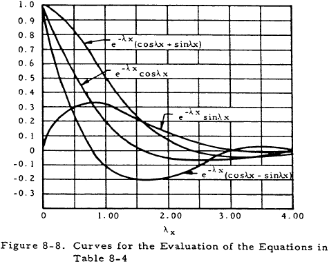
By substituting the values of displacements and angles obtained from Tables 8-2 and 8-3 into Equations (8-9) and (8-10) and solving these Qo and Mo may be obtained as functions of pressure and the geometry and material of the pressure vessel. The discontinuity stresses are given as functions of Qo, Mo, and position in Figure 8-4. The curves given in Figure 8-8 are useful in the evaluation of the stresses given by the equations in Table 8-4.
The previously described method of obtaining discontinuity stresses is time-consuming, although it provides insight into the nature of these stresses. More rapid solutions for the discontinuity stresses in thin cylindrical pressure vessels with flat or conical heads may be obtained through the curves given in Sections 8.3.1.2.2.3 and 8.3.1.2.2.4.
| Form of Vessel | Radial Displacement |
|---|---|
|
$$ w_{m1} = { p ~r^2 \over ET \cos{\alpha} } \left( 1 - {\mu \over 2} \right) $$ |
|
$$ w_{m1} = { p ~r^2 \over 2ET } \left(1 - \mu \right) $$ |
|
$$ w_{m1} = { p ~r^2 \over 2ET } \left( 2 - \mu - { r \over R_{mer} } \right) $$ |
|
$$ w_{m2} = { p ~r^2 \over Et } \left( 1 - {\mu \over 2} \right) $$ |
| Form of Vessel | Radial Displacement | Angle of Rotation |
|---|---|---|
|
$$ w_1 = { 12 (1 - \mu^2) \over ET^3 } \left( { -Q_o \over 2 \lambda_1^3 } \sin^2{\phi_o} - { M_o \over 2 \lambda_1^2 } \sin{\phi_o} \right) $$
$$ w_2 = { 12 (1 - \mu^2) \over Et^3 } \left( { Q_o \over 2 \lambda_2^3 } \sin^2{\phi_o} - { M_o \over 2 \lambda_2^2 } \sin{\phi_o} \right) $$
|
$$ \theta_1 = { 12 (1 - \mu^2) \over ET^3 } \left( { Q_o \over 2 \lambda_1^2 } \sin{\phi_o} - { M_o \over \lambda_1 } \right) $$
$$ \theta_2 = { 12 (1 - \mu^2) \over Et^3 } \left( { Q_o \over 2 \lambda_2^2 } \sin{\phi_o} - { M_o \over \lambda_2 } \right) $$
|
| Note: $$ \lambda_1 = \sqrt[\uproot{1} \scriptstyle 4]{ 3(1 - \mu^2) / r^2 T^2 } $$ $$ \lambda_2 = \sqrt[\uproot{1} \scriptstyle 4]{ 3(1 - \mu^2) / r^2 t^2 } $$ | ||
| Expressions for Discontinuity Stresses of Distance x Measured Along Meridian from Discontinuity Circle AA (see Figure 8-7) |
|---|
|
(1) Hoop Normal Stress:
$$ F_t = { 2 \lambda r \over t } \left({r \over R_t}\right) e^{-\lambda x} [ Q_o \cos{\lambda x} - \lambda M_o ( \cos{\lambda x} - \sin{\lambda x} ) ] $$
|
|
(2) Meridional Shear Stress:
$$ F_{smer} = { r \over t R_t } \sqrt{ r \over R_t } e^{-\lambda x} [ Q_o ( \cos{\lambda x} - \sin{\lambda x} ) + 2 \lambda M_o \sin{\lambda x} ] $$
|
|
(3) Maximum Meridional Bending Stress:
$$ F_{bmer} = { 6 r \over t^2 R_t } \left({1 \over \lambda}\right) e^{-\lambda x} [ -Q_o \sin{\lambda x} + \lambda M_o ( \cos{\lambda x} + \sin{\lambda x} ) ] $$
|
|
(4) Maximum Hoop Bending Stress:
$$ F_{bt} = \mu F_{bmer} + {E t \over 2} \left({ \cot{\phi_o} \over R_t }\right) \left[{ 6 (1 - \mu^2) \over E ~t^3 \lambda^2 }\right] e^{-\lambda x} [ Q_o (\cos{\lambda x} + \sin{\lambda x}) - 2 \lambda M_o \cos{\lambda x} ] $$
|
| Note: For stress in cylinder, λ = λ2. For stress in head, let λ = λ1 and t = T. |
8.3.1.2.2.2.1 Sample Problem - Discontinuity Forces in Cylindrical Pressure Vessel with Dished Head
Given: The pressure vessel shown in Figure 8-9.
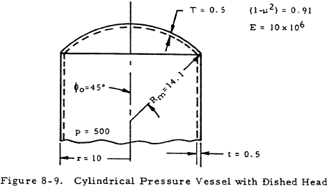
Find: The discontinuity force and moment at the junction of the cylinder and its head.
Solution: From Tables 8-3 and 8-4,
$$ w_{m1} = { p ~r^2 \over 2ET } \left( 2 - \mu - { r \over R_{m} } \right) $$ $$ w_{m2} = { p ~r^2 \over Et } \left( 1 - {\mu \over 2} \right) $$and
From Table 8-3,
$$ \lambda_1 = \sqrt[\uproot{1} \scriptstyle 4]{ 3(1 - \mu^2) / r^2 T^2 } $$and
$$ \lambda_2 = \sqrt[\uproot{1} \scriptstyle 4]{ 3(1 - \mu^2) / r^2 t^2 } $$In this case,
$$ \lambda_1 = \lambda_2 = \sqrt[\uproot{1} \scriptstyle 4]{ 3(0.91) / (10^2) (0.5^2) } = 0.575 $$Substituting this and other parameters into the above equations gives
| wm1 = 4.97 × 10 -3 |
| wm2 = 2.12 × 10 -3 |
| w1 = −15.2 × 10 -6Qo − 9.36 × 10 -6Mo |
| w2 = 15.2 × 10 -6Qo − 9.36 × 10 -6Mo |
Substituting these into Equation (8-9) and solving for Qo gives
Substituting the pressure vessel parameters into the equations for θ1 and θ2 in Table 8-3 gives
| θ1 = 9.38 × 10 -6Qo − 15.2 × 10 -6Mo |
| θ2 = 9.38 × 10 -6Qo + 15.2 × 10 -6Mo |
Applying Equation (8-10) gives
Thus,
The values obtained for Qo and Mo may be substituted into the equations in Table 8-4 to obtain the discontinuity stresses. Superposing these discontinuity stresses on the membrane stresses then gives the total stresses at the head-cylinder junction.
8.3.1.2.2.3 Discontinuity Stresses in Thin Cylindrical Pressure Vessels with Flat Heads
For flat-headed pressure vessels, the only significant discontinuity stresses are in the meridional direction. Thus, such a vessel will have as its maximum stress either the membrane stress in the tangential direction (pd/2t), or the stress in the axial direction if the discontinuity stress is great enough.
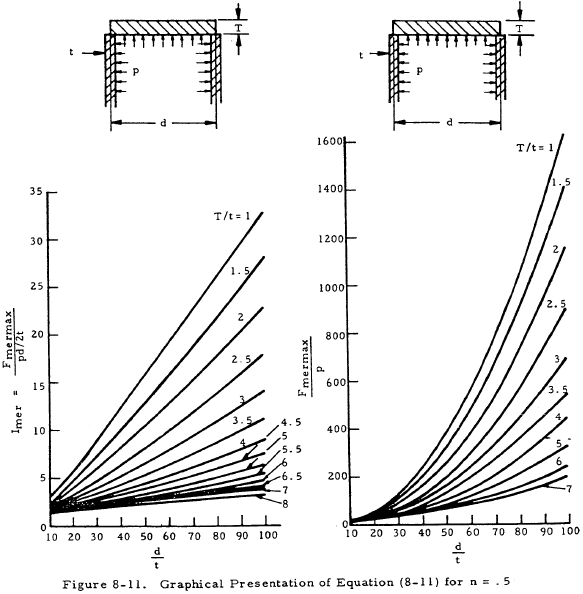
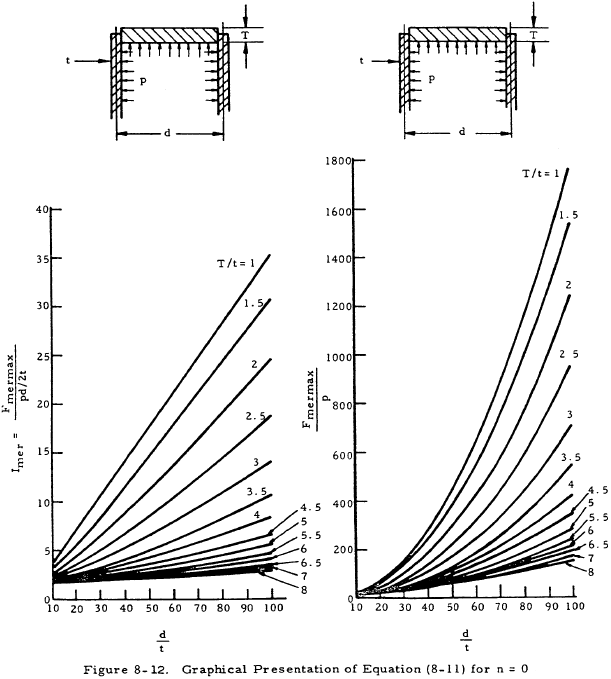
In treating axial discontinuity stresses, a stress ratio, Imer may be defined to be the ratio of the maximum stress in the meridional direction to the tangential membrane stress (Fmermax/pd/2t). The advantage of this stress ratio is that it tells immediately whether the tangential membrane stress or the total axial stress is the maximum stress.
The following equation was derived for the stress ratio Imer in a flat headed cylinder as a function of head thickness T and cylinder thickness t.
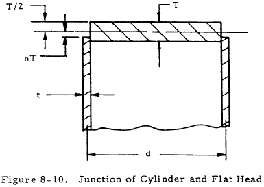
Here, nT is the distance from the midplane of the head thickness to the joint as shown in Figure 8-10. The coefficients C1 through C11 are given below:
| C1 = 2.94317 | C6 = 1.90702 |
| C2 = 3. 74071 | C7 = 4.84761 |
| C3 = 1.00000 | C8 = 1.02862 |
| C4 = 0.908912 | C9 = 2.66667 |
| C5 = 0.385077 | C10 = 4.40610 |
| C11 = 1.46869 |
The first term in Equation (8-11) represents the axial membrane stress in the cylinder, and the second term accounts for discontinuity stresses.
Equation (8-11) is presented graphically in Figure 8-11 for n = 0.5 (junction at inner surface of head) and in Figure 8-12 for n = 0 (head fitted inside the shell).
8.3.1.2.2.3.1 Sample Problem - Discontinuity Stresses in Pressure Vessels with Flat Heads
Given: The pressure vessel shown in Figure 8-13.
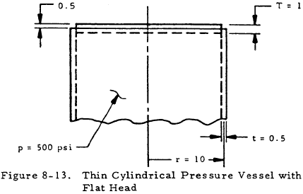
Find: The maximum circumferential and meridional stresses in the cylinder.
Solution: Since the only significant discontinuity stresses in a flat-headed cylinder are in the axial direction, the maximum circumferential stress may be taken to be the membrane stress in that direction. Thus, using Equation (8-5) gives
The distance from the center of the head to the joint (nT) is equal to zero. Thus, n = 0 and the graphs in Figure 8-12 may be used. Here, d/t = 40 and T/t = 2. From Figure 8-12,
$$ I_{mer} = { F_{mermax} \over pd/2t } = 8.6 $$Since this stress ratio is greater than one, Fmermax > Fmt. Rearranging and substituting the correct values into the above relation gives
8.3.1.2.2.4 Discontinuity Stresses in Thin Cylindrical Pressure Vessels with Conical Heads
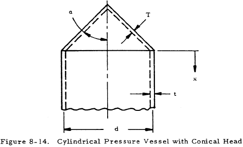
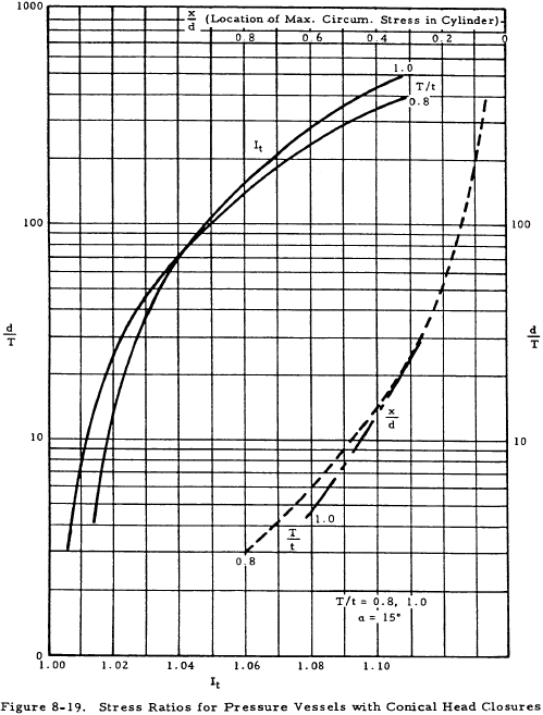
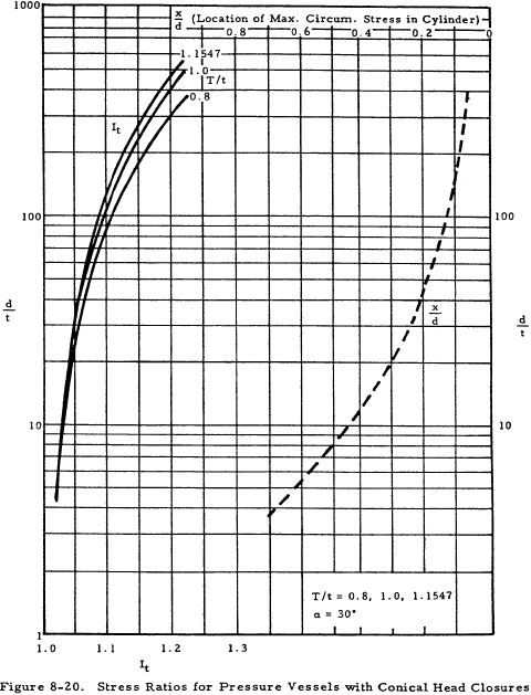
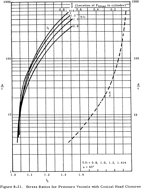
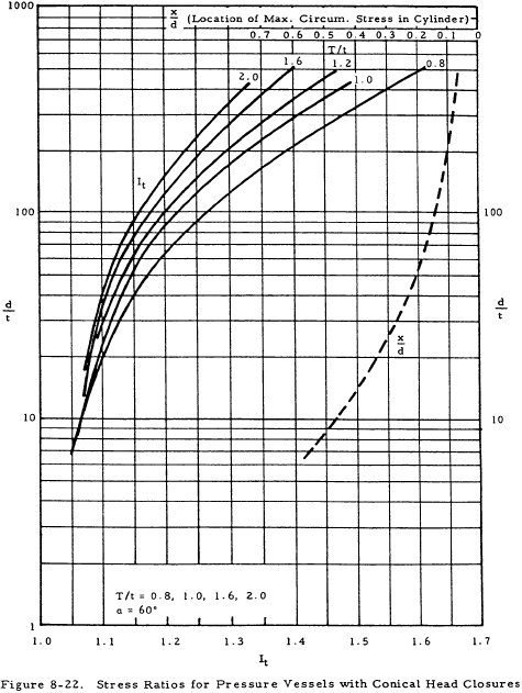
For conical headed pressure vessels, there may exist appreciable discontinuity stresses in the circumferential and axial directions as well as an axial shear stress. Stress ratios are defined here in the same way as for flat-headed vessels. Imer is the ratio of the maximum axial stress to the tangential stress (Fmermax/pd/2t) as before, and It = Ftmax/pd/2t and Is = Fsmax/pd/2t where Ftmax and Fsmax are the maximum circumferential and shear stresses, respectively.
Pertinent geometric parameters for a cylindrical pressure vessel with a conical head are shown in Figure 8-14.
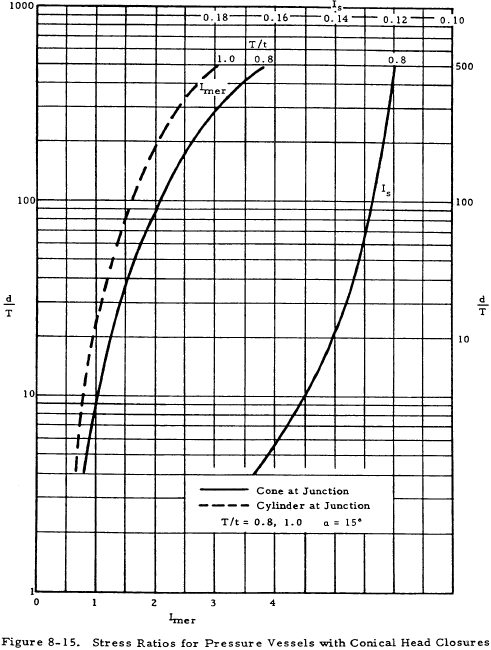
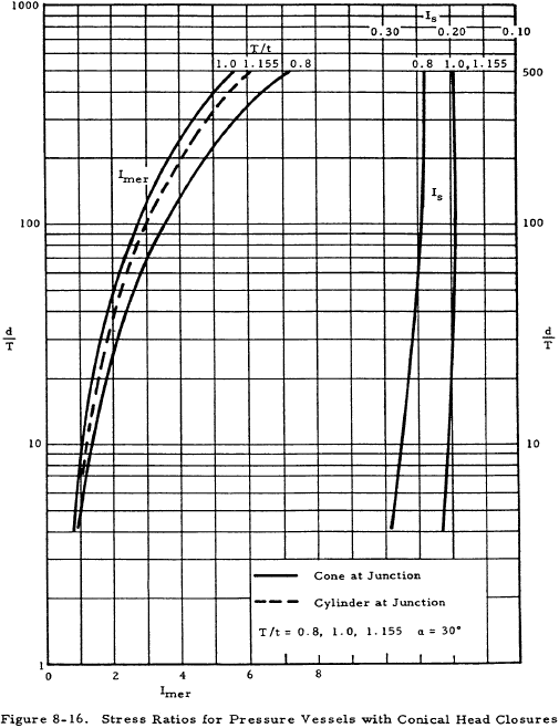
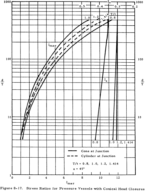
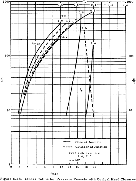
Figures 8-15 through 8-18 give the stress ratios, Imer and Is, for various cone apex angles. The maximum axial and shear stresses at the junction may in turn be calculated from these. Figures 8-19 through 8-22 show the stress ratio It from which the maximum circumferential stresses in a cylinder may be calculated. For the maximum axial stress, a solid line is used if the stress is located in the cylinder, and a dashed line is used in Figures 8-15 through 8-19 if it is located in the conical head.
It is important to note that when an internal pressure is applied to a conical headed vessel, the cylinder always deflects outward and the conical head inward. Thus, it is impossible to design a conical head to eliminate moment and shear at the junction. It may be seen from Figures 8-15 through 8-18 that the greatest stress is the axial stress at the junction and that it is desirable to make the cone and cylinder equally thick if α is less than 45 degrees in order to minimize this axial stress. If this is not possible, the cone should have a greater thickness than the cylinder. Vertex angles of greater than 45 degrees require a thicker head.
8.3.1.2.2.4.1 Sample Problem - Discontinuity Stresses in Pressure Vessels with Conical Heads
Given: The pressure vessel shown in Figure 8-23.
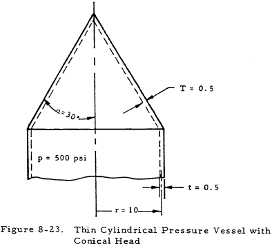
Find: The maximum meridional, tangential, and shear stresses at the head-cylinder junction.
Solution: For this pressure vessel, d/T = 40 and T/t = 1. Figures 8-16 and 8-20 give stress ratios for conical heads with an angle of 30°. From these figures,
| Imer | = | 1.8 |
| It | = | 1.055 |
| Is | = | 0.205 |
The circumferential membrane stress is
$$ { pd \over 2t } = { 500 (20) \over 2 (0.5) } = 10,000 ~\text{psi} $$Applying the definitions of the stress ratio gives
Since the appropriate graphs in Figure 8-16 are solid lines, Fmermax and Fsmax occur in the cone at the junction. From the dashed line in Figure 8-20, the location of Ftmax, x/d is 0.22. Thus, Ftmax occurs at x = 0.22 d = 4.4 inches from the junction of the cylinder and its head in the cylinder.
We have a number of structural calculators to choose from. Here are just a few:
8.3.1.3 Buckling of Thin Simple Pressure Vessels Under External Pressure
In previous sections, it was assumed that the pressure is either internal or external, but of small enough magnitude not to cause buckling. However, thin pressure vessels must be checked for buckling if they are externally loaded.
8.3.1.3.1 Buckling of Thin Simple Cylinders Under External Pressure
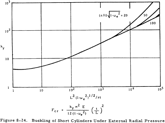
The formula for the critical stress in short cylinders (L2/rt < 100) which buckle elastically under radial pressure is
where ky is obtained from Figure 8-24. If the membrane stress in the cylinder is greater than this, the cylinder will buckle.
The critical stress for long cylinders, [100 t/r < (L/r)2 < 5 r/t ], under external radial pressure is
For very long cylinders, [(L/r)2 > 5 r/t ], the buckling stress is given by
where η is the plasticity-reduction factor given in this case by
Sample Problem - Buckling of Thin Simple Cylinders Under External Pressure
Given: The cylinder shown in Figure 8-25.
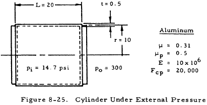
Find: The critical buckling stress, Fcr and determine whether the cylinder will buckle.
Solution:
$$ {L^2 \over rt} = {20^2 \over 10 (0.5)} = 80 $$Since this ratio is less than 100, Equation (8-12) for short cylinders may be used. Before proceeding further, the elastic Poisson's ratio must be found. From the nomenclature section,
$$ \mu_e = \left[ \mu_p \left( {E_s \over E} - 1 \right) + \mu \right] { E \over E_s } $$Assume the critical stress is less than the proportional limit of the material. If this is true, E = Es, and thus, μe = μ. Compute
From Figure 8-24, ky = 12.2. Substituting this into Equation (8-12) gives
Since this is less than the proportional limit of the material, the original assumption is correct. If it were not correct, a value of Fcr would have to be assumed and a value of Es corresponding to this value found. This value would, in turn, be used to calculate μe which would be used in the Equation (8-12) to calculate Fcr. This trial and error process would have to be repeated until the assumed and calculated values of Fcr were in agreement.
From Equation (8-5), the stress in the cylinder is
Since this is less than Fcr, the cylinder does not fail.
8.3.1.3.2 Buckling of Thin Simple Spheres Under External Pressure
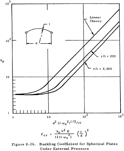
For computation of elastic-buckling stresses of thin spherical plates under external pressure, Equation (8-16) applies for all diameter ranges.
where kp is given in Figure 8-26.
8.3.1.4 Stresses in Simple Cylindrical Pressure Vessels Due to Supports
Figure 8-27 shows a cylindrical pressure vessel resting on saddle supports.
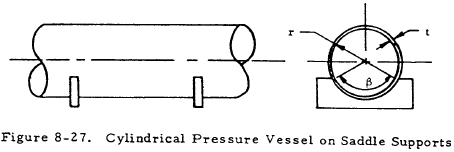
There are high local longitudinal and circumferential stresses adjacent to the tips of the saddles. Although these stresses are difficult to predict exactly, their maximum value will probably not exceed that given by Equation (8-17) if the cylinder fits the saddle well.
In this equation, P is the reaction at each saddle and R, t, and β are as shown in Figure 8-27 where β is in degrees. Equation (8-17) contains no term for the thickness of the saddle since stresses are practically independent of this for the ordinary range of dimensions.
The maximum reaction, P, that the vessel can sustain is about twice the value that will produce a maximum stress equal to the yield point of the material according to Equation (8-17).
If a pipe is supported in flexible slings instead of in rigid saddles, the maximum stresses occur at the points of tangency between the sling and pipe section. These stresses are usuallyless than the corresponding stresses in a saddle supported pipe, but are of the same order of magnitude.
We have a number of structural calculators to choose from. Here are just a few:
8.3.1.5 Crippling Stress of Pressurized and Unpressurized Thin Simple Cylinders
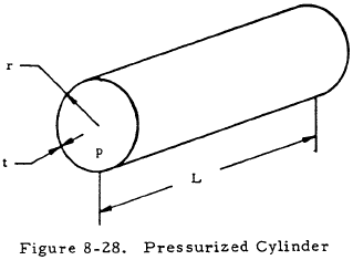
The crippling stress of thin simple cylinders is increased if internal pressure is applied. The following sections present curves to determine the crippling stress in pressurized and unpressurized cylinders subjected to compression, bending, torsion, or any combination of these. The parameters for such a cylinder are shown in Figure 8-28. Only buckling in the elastic range is considered in this section.
8.3.1.5.1 Crippling Stress of Simple Thin Cylinders in Compression
8.3.1.5.1.1 Crippling Stress of Unpressurized Simple Thin Cylinders in Compression
Equation (8-18) is an empirical relationship for the crippling stress of short cylinders (L/r ≤ 1).
For long cylinders (L/r > 1), the best fitting relationship for the crippling stress is
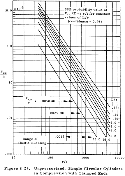
For 99% probability values of Fcc, Figure 8-29 should be used.
Crippling occurs when the average compressive stress in the cylinder exceeds Fcc.
8.3.1.5.1.2 Crippling Stress of Pressurized Simple Thin Cylinders in Compression
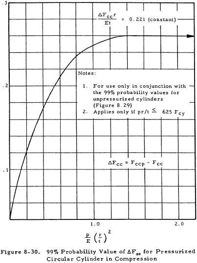
Figure 8-30 gives in graphical form the incremental increase in the crippling stress (ΔFcc) of a cylinder due to internal pressure. These curves are for 99% probability values. Because of limited testing of pressurized cylinders, the value obtained for ΔFcc can be considered reliable only in the ranges 1 < L/r < 6, 600 < r/t < 2800 and pr/t < 0.625Fcy.
8.3.1.5.2 Crippling Stress of Simple Thin Cylinders in Bending
8.3.1.5.2.1 Crippling Stress of Unpressurized Simple Thin Cylinders in Bending
Figure 8-31 gives 99% probability curves for the crippling stress of unpressurized cylinders in bending. These curves parallel those for unpressurized cylinders in compression but yield crippling stresses about 12% greater.
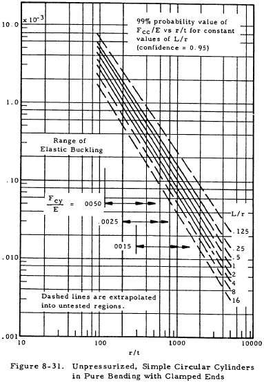
Crippling failure occurs when the maximum bending stress in the cylinder (Mr/I ) exceeds Fcc.
8.3.1.5.2.2 Crippling Stress of Pressurized Simple Thin Cylinders in Bending
Figure 8-32 gives the incremental increase in the crippling stress (ΔFcc) of a cylinder in bending due to internal pressure. This curve is based on experiments on pressurized cylinders that were preloaded axially to balance the longitudinal stress, pr/2t, due to internal pressure. It should be noted that this curve is based on very limited data.
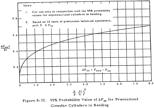
8.3.1.5.3 Crippling Stress of Simple Thin Cylinders in Torsion
8.3.1.5.3.1 Crippling Stress of Unpres surized Simple Thin Cylinders in Torsion
Torsional buckling of thin, unpressurized cylinders does not exhibit the sudden snap-through behavior observed in the case of compression and bending. Instead, the buckling process under torsion is more gradual and a slight difference is observed between initial and ultimate buckling. However, this difference is too small to be of any value so that the critical buckling stress is taken to be the failure stress.
Figure 8-33 gives the 99% probability values for the crippling shear stress of cylinders in torsion. These curves are applicable if
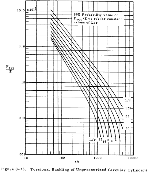
However, analysis indicates that the range of use of these curves may be amended to
Failure occurs if the shear stress in a cylinder under torsion Tr/Ip is greater than the crippling shear stress, Fscc.
8.3.1.5.3.2 Crippling Stress of Pressurized Simple Thin Cylinders in Torsion
Figure 8-34 gives the incremental increase in the crippling shear stress of a cylinder in torsion (ΔFscc) due to internal pressure. Since few tests are available on buckling of circular cylinders under torsion and these tests are for very low pressure ranges, design curves may not be established on a statistical basis.
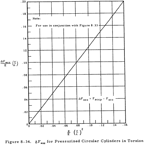
8.3.1.5.3.2.1 Sample Problem - Cripppling Stress of Pressurized Simple Thin Cylinders in Torsion
Given: The pressurized cylinder shown in Figure 8-35.

Find: The crippling shear stress, Fsccp, and examine for failure by crippling.
Solution: L/r = 8 and r/t = 100. From Figure 8-33,
$$ { F_{scc} \over E } = 8 \times 10^{-4} $$for unpressurized cylinders. Thus, Fscc = 8,000 psi.
From Figure 8-34,
$$ { \Delta F_{scc} \over E } \left({r \over t}\right) = 0.125 $$Thus,
The crippling stress in a cylinder under pressure (Fsccp) is equal to that of an unpressurized cylinder plus ΔFscc.
Fsccp = Fscc + ΔFscc = 8,000 + 10,000 = 18,000 psi
It can be seen that internal pressure more than doubles the resistance of the cylinder to crippling. The shear stress in the cylinder is
Since this stress is greater than Fsccp, the cylinder will fail by crippling.
8.3.1.5.4 Interaction Formulas for the Crippling of Pressurized and and Unpressurized Cylinders
Table 8-5 gives interaction relationships for various combinations of loads. The combined load interactions apply to the initial buckling of both pressurized and unpressurized thin-walled circular cylinders. The terms used for pressurized cylinders are defined as follows:
$$ R_b = { \text{applied bending moment} \over \text{critical bending moment} } $$ $$ R_c = { \text{applied compressive load} \over \text{critical compressive load} } $$ $$ R_s = { \text{applied transverse shear load} \over \text{critical transverse shear load} } $$ $$ R_{st} = { \text{applied torsional moment} \over \text{critical torsional moment} } $$The terms for unpressurized cylinders are defined in the same way except that stress ratios are used rather than load ratios.
| Combined Loading Condition | Interaction Equation (99% Probability Values) |
|---|---|
| Axial Comp. + Pure Bending | $$ R_c + R_b = 1.0 $$ |
| Axial Comp. + Pure Bending + Transverse Shear | $$ R_c ~\sqrt[\uproot{1} \scriptstyle 3]{ R_s^3 + R_b^3 } = 1.0 $$ |
| Pure Bending + Transverse Shear | $$ R_s^3 + R_b^3 = 1.0 $$ |
| Axial Comp. + Torsion | $$ R_c + R_{st}^2 = 1.0 $$ |
| Axial Tens. + Torsion | $$ R_{st}^3 - R_t = 1.0 ~~~~~ R_t \lt 0.8 $$ |
| Pure Bending + Torsion | $$ R_b^{1.5} + R_{st}^2 = 1.0 $$ |
| Pure Bending + Torsion + Transverse Shear |
$$ R_b^{~p} + (R_s + R_{st})^q = 1.0 $$
where:
1.5 ≤ p ≤3.0
2.0 ≤ q ≤3.0 |
| Axial Comp. + Pure Bending + Transverse Shear + Torsion | $$ R_c + R_{st}^2 + \sqrt[\uproot{1} \scriptstyle 3]{ R_s^3 + R_b^3 } = 1.0 $$ |
| Axial Load (Tens. or Comp.) + Pure Bending + Torsion | $$ R_s + R_b + R_{st}^2 = 1.0 $$ |
8.3.1.5.4.1 Sample Problem - Crippling Interaction of Simple Thin Cylinders in Compression and Bending
Given: The cylinder shown in Figure 8-36.
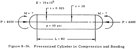
Find: The maximum bending moment, M.
Solution: From Figure 8-29, Fcc/E = 1.6 × 10⁻⁴ for compressive loading. Thus,
$$ F_{cc} = (1.6 \times 10^{-4})(10 \times 10^6) = 1,600 ~\text{psi} $$From Figure 8-30, ΔFccr/Et = 0.235. Thus,
For compressive loading,
The critical compressive load is thus,
$$ 7470 A = 7470 [ \pi (20) (0.025) ] = 11,700 ~\text{psi} $$Since the applied compressive load is 6,000 lb,
From Table 8-5,
$$ R_c + R_b = 1.0 $$Thus,
$$ R_b = 1.0 - R_c = 1.0 - 0.513 = 0.487 $$Now, the allowable bending load may be found once the critical bending load is found. From Figure 8-31 and 8-32, Fcc = 2,200 and ΔFcc = 9,000. Thus,
The formula for the critical bending moment is
Since,
$$ R_b = { \text{applied bending moment} \over \text{critical bending moment} } = 0.487 ~\text{,} $$ $$ M = R_b M_{cr} = 0.487 (5,500) = 2,430 ~\text{in-lb} $$