Analysis of Simple Columns
This page provides the sections on the analysis of simple columns from the "Stress Analysis Manual," Air Force Flight Dynamics Laboratory, October 1986.
Other related chapters from the Air Force "Stress Analysis Manual" can be seen to the right.
- Analysis of Simple Columns
- Column Data
- Constants for Straight Line Equation
- Crippling of Columns
- Analysis of Complex Columns
2.1 Introduction to Column Analysis
The stresses that a structural element can sustain in compression are functions of several parameters. These parameters are:
- the length of the element along its loading axis,
- the moment of inertia of the element normal to its loading axis,
- the cross-sectional variation of the element with length,
- the eccentricity of the applied load,
- the continuity of the integral parts of the element,
- the cross-sectional characteristics of the element,
- the homogeneity of the element material,
- the straightness of the element, and
- the end fixity of the element.
The effects of these parameters can be categorized by first establishing certain necessary assumptions. For the following analysis, it is assumed that the material is homogeneous and isotropic. It is further assumed that the element is initially straight and, if it is composed of several attached parts, that the parts act as integral components of the total structural configuration.
The remainder of the previously mentioned parameters dictate more general classifications of compression elements. If a compression element is of uniform cross section and satisfies the previously mentioned assumptions, it is referred to as a simple column and is treated in the first part of this chapter. On the other hand, compression members having variable cross-sectional properties are called complex columns and are covered in the latter part of this chapter. Stepped and latticed columns are included in the treatment of complex columns.
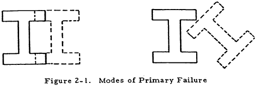
The possible basic types of failure defined for columns are primary and secondary failure. Primary failure occurs when a column fails as a whole and may be defined by the fact that cross sections of the element retain their original shape although they may be translated and/or rotated with respect to their original position. If cross sections are translated but not rotated, the primary failure is of the bending type. Failures for which cross sections of a column are either rotated or rotated and translated are treated in the section on torsional instability.
If a column experiences a failure due to lateral bending at a stress level below the elastic limit of the material, it is defined to be a long column while failures at a maximum stress greater than the elastic limit are characteristic of short columns.
Secondary failures occur when buckling or crippling occur in sections of a column before it is loaded enough to produce a primary failure.
A column failure of a selected element is influenced by the eccentricity of the applied load and by the end fixity of the element. Both of these dictate boundary conditions that modify the solutions to the differential equations governing column response.
In general, a column must be designed to prevent both the bending and torsional types of primary failure as well as crippling. Crippling is likely to occur in columns having thin portions in their cross sections. The torsional type of primary failure is likely to occur at a lower load than the bending type in columns having cross sections of relatively low torsional stiffness. Closed sections have enough torsional stiffness to insure that any primary failure will be of the bending type so they must only be designed against this and crippling.
Need a Column Buckling Calculator?
Try this column buckling calculator.
- buckling analysis of long and intermediate-length columns loaded in compression
- loading can be either central or eccentric
2.2 Nomenclature for Column Analysis
| A | = | area |
| a | = | linear dimension as indicated in diagrams |
| b | = | linear dimension as indicated in diagrams |
| C | = | coefficient of constraint = (L/L' )2 |
| CBT | = | torsion - bending constant |
| C | = | distance from neutral axis to the concave side of loaded column |
| D | = | diameter |
| E | = | modulus of elasticity |
| Er | = | reduced modulus of elasticity |
| Es | = | secant modulus of elasticity |
| Et | = | tangent modulus of elasticity |
| e | = | eccentricity of loading |
| e | = | strain |
| ec/ρ2 | = | eccentric ratio |
| Facol | = | working concentrically loaded column stress |
| Fb | = | working bending stress |
| Fc | = | allowable compressive stress |
| Fcb | = | working compressive stress in bending |
| Fcc | = | allowable crippling stress |
| Fco | = | empirical constant in Johnson parabolic equation (column yield stress) |
| Fcol | = | maximum fiber stress for primary failure of a column |
| Fcb | = | proportional limit in compression |
| Fcy | = | compressive yield stress |
| FS | = | factor of safety |
| f | = | calculated stress |
| fc | = | calculated compressive stress |
| f1 | = | stress at which the secant modulus of elasticity is equal to 0.7 |
| G | = | modulus of elasticity in shear |
| h | = | height |
| I | = | moment of inertia |
| Ip | = | polar moment of inertia |
| J | = | torsion constant |
| K | = | spring constant |
| K | = | empirical constant |
| k | = | empirical constant |
| L | = | length |
| L' | = | effective length = L/√C |
| L/ρ | = | slenderness ratio |
| L'/ρ | = | effective slenderness raho |
| (L'/ρ)cr | = | critical effective slenderness ratio |
| M | = | empirical constant in straight line column equation |
| N | = | empirical constant in straight line column equation |
| n | = | empirical constant in Ramberg-Osgood equation |
| P | = | axial load |
| Pa | = | allowable load |
| Pcc | = | crippling load |
| Pcr | = | critical load |
| Pe | = | Euler critical load |
| r | = | radius |
| T | = | torque |
| t | = | thickness |
| x, y, z | = | rectangular coordinates |
| ϵ | = | Ee/f1 where e is strain |
| μ | = | Poisson's ratio |
| μ | = | torsional spring constant |
| ρ | = | radius of gyration = \( \sqrt{I/A} \) |
| Σ | = | summation |
| σ | = | fc/f1 |
| θ | = | angular deflection |
| ϕ | = | angular deflection |
2.3 Simple Columns
A simple column acts as a single unit and has a uniform cross section along its length. Such columns are treated in the following material.
2.3.1 Primary Failure of Simple Columns
A simple column has a primary failure when its cross sections are translated and/or rotated while retaining their original shape, that is, when the column fails as a whole without local instability. If the column cross sections are translated but not rotated as shown to the left of Figure 2-1, it is said to fail by bending while pure rotation or a combination of rotation and translation are characteristic of torsional failures.
2.3.1.1 Column Data Applicable to Both Long and Short Columns
A stable section (not subject to crippling) testing for various lengths will generate data of the form shown in Figure 2-2. The stress Fcol is the stress at failure, and L'/ρ is the ratio of the effective column length to the radius of gyration of the section. This L'/ρ ratio is called the effective slenderness ratio of the column.
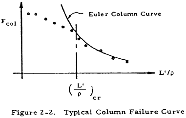
From the figure, it is apparent that the Euler column curve is quite accurate beyond a critical L'/ρ which defines the separation between long and short columns. A great amount of test data, collected for particular materials, is available and eliminates the need to determine whether a long or a short column curve is applicable. A summary of column allowable curves that are applicable to both long and short columns is outlined and presented on the following pages. These curves are based upon the tangent modulus equation which is discussed in Section 2.3.1.11.1. The column allowables are based on minimum guaranteed properties, Basis A, or probability properties, Basis B, if the latter are available. The pertinent basis is indicated in the figures.
The figures for the column data can be found on this page.
2.3.1.2 Sample Problem - Column Data Applicable to Both Long and Short Columns
Given: The 0.6 in. square concentrically loaded column shown in Figure 2-35.

Find: The critical load, Pcr, by using column curves applicable to both long and short columns.
Solution: Since the column is pinned at both ends; L' = L = 6 in. For a square, I = b4/12 and A = b2. Thus,
$$ \rho = \sqrt{ ~I \over A } = \sqrt{ b^2 \over 12 } = \sqrt{ (0.6)^2 \over 12 } = 0.173 ~\text{in} $$ $$ { L' \over \rho } = { 6 ~\text{in} \over 0.173 ~\text{in} } = 34.6 $$From Figure 2-3, curve 2, find Fcol = 56,200 psi. Thus,
$$ P_{cr} = F_{col} A = 56,200 (0.6)^2 = 20,200 ~\text{lb} $$2.3.1.3 Bending Failure of Concentrically Loaded Long Columns
In the process of describing column behavior in this chapter, the simplest cases are covered first and then various complications are covered. Historically, the first type of column to be successfully studied was the long concentrically loaded one for which Euler developed an equation giving the buckling load in terms of column parameters. This is also the simplest case.
The Euler formula, which is perhaps the most familiar of all column formulas, is derived with the assumptions that loads are applied concentrically and that stress is proportional to strain. Thus, it is valid for concentrically loaded columns that have stable (not subject to crippling) cross sections and fail at a maximum stress less than the proportional limit, that is, concentrically loaded long columns. The form of the Euler formula is
| $$ { P_{cr} \over A } = { C \pi^2 E \over (L / \rho)^2 } $$ | or |
| $$ { P_{cr} \over A } = { \pi^2 E \over (L' / \rho)^2 } $$ |
Here, P/A is the ratio of the axially applied load at failure to the cross-sectional area of the column. E is the modulus of elasticity of the column and L/ρ is the ratio of the column length to the least radius of gyration of its section. The radius of gyration is defined to be equal to \(\sqrt{I/A}\), where I is the moment of inertia of the section. The constant, C, which is called the coefficient of constraint, is dependent upon end restraints and is discussed in Section 2.3.1.4. In the second form of Equation (2-1), L' is an effective length which takes into account end restraint conditions.
Need a Column Buckling Calculator?
Try this column buckling calculator.
- buckling analysis of long and intermediate-length columns loaded in compression
- loading can be either central or eccentric
2.3.1.4 Coefficient of Constraint for End Loaded Columns
In the discussion of columns, the coefficient of constraint C often occurs. As was mentioned before, this coefficient depends upon the manner in which the ends of a column are restrained, which, in turn, determines the boundary conditions that must be satisfied by the equations describing the column.
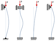
Sometimes, the use of a coefficient is avoided by using an effective length L' instead of the actual length L in formulas derived for a column with both ends pinned of length L. The term L' is then the distance between points of inflection of the loaded column curve. For example, the effective length of a column of length L that is rigidly supported at both ends is L/2 as can be seen in Figure 2-36.
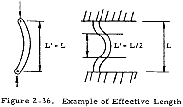
The relationship between L' and L, and C is
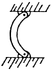
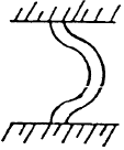
By assuming various combinations of idealized end restraints, a table of theoretical end constraint factors may be constructed. This is shown in Table 2-1.
| Type of Fixity |

|
|

|
|
| C | 0.25 | 1.00 | 2.05 | 4.00 |
The end restraints of an actual column are never exactly equivalent to pinned or fixed ends, but lie somewhere between the two extremes. This discrepancy is due to the fact that a pinned joint is never entirely frictionless and a member to which a column is fixed is never perfectly rigid.
Cases for which one or both of the ends of a column are fixed to nonrigid members may be treated by considering these ends to be restrained by a torsional spring of spring constant μ. The constant μ is defined to be dT/dθ where T is a torque applied to the support at the point where the column is attached and θ is the angle of twist at this point. Given this definition, μ may be calculated by applying formulas from strength of materials to the member to which the column is attached before attachment. For example, consider the column shown in Figure 2-37. The torsional spring constant for the end is found by considering the beam supporting the column and calculating dT/dθ where T and θ are as shown in the middle diagram. dT/dθ is a constant for small deflections so T/θ may be found from beam formulas. The column is then redrawn with the attached beam replaced by an equivalent torsional spring.
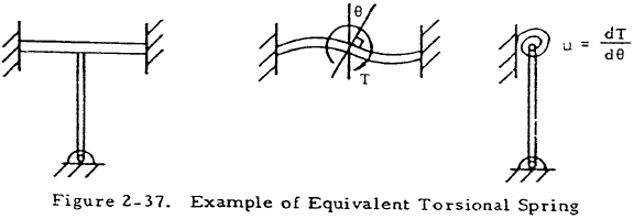
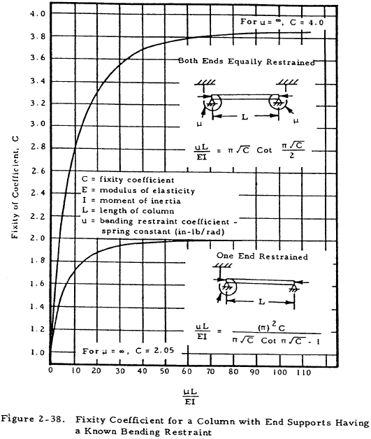
Equations have been developed that give the end fixity coefficient, C, as a function of μ, L, E, and I for columns equally elastically restrained at both ends and for those pinned at one end. These equations are given and plotted in Figure 2-38. From these plots, it can be seen that C approaches the value corresponding to a fixed end rather than an elastically restrained end as μ increases. Likewise, C approaches the value corresponding to a pinned end as the spring constant approaches zero.
At times, a column may be supported along its length as well as at the ends. For example, the column shown in Figure 2-39 is supported at its midsection by another member.
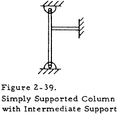
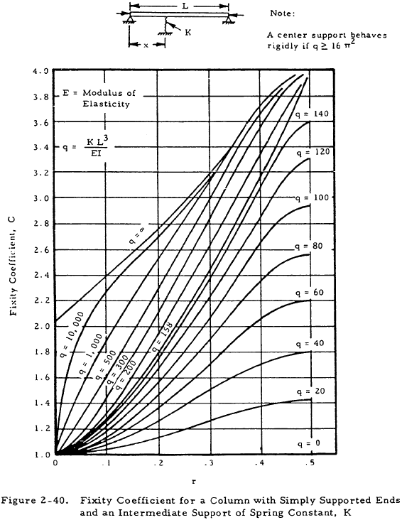
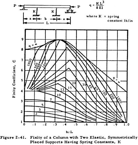
In order to treat such a case, namely that illustrated in Figure 2-39, we may consider the member supporting the column at its midsection to be a spring of spring constant K lbs/in which may be found by applying strength of materials to the support. Charts that give the coefficients of restraint of a pinned column with a single lateral support along its midsection or two lateral supports symmetrically placed on its midsection are available. Figure 2-40 shows a simply supported column with one lateral restraint and gives the coefficient of constant of such a column as a function of column parameters. Figure 2-41 shows a simply supported column with two symmetrically placed lateral restraints and gives the coefficient of constraint as a function of column parameters.
The previous discussion of coefficients of constraint was limited to relatively simple cases. At times, however, a column may be attached to members for which an equivalent torsional spring constant is not easily found or it may be attached in more complicated ways than those previously discussed. In such cases, certain general rules may be applied.
In normal practice, the coefficient of constraint is less than two and the effect of end fixity is smaller for short columns than for long ones.
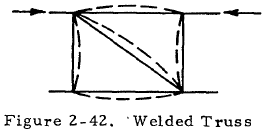
The ends of a compression member in a welded truss of steel tubes, like those that are often used in aircraft structures, cannot rotate without bending all of the other members at the end joints. Such a truss is shown in Figure 2-42. It is difficult to obtain the true end fixity of a compressive member in such a truss since the member may buckle either horizontally or vertically and iv restrained by the torsional and bending rigidity of many other members. It is usually conservative to assume C = 2.0 for all members. A smaller coefficient of constraint might be used for a heavy compressive member restrained by comparatively light members. Likewise, a larger coefficient of constraint may hold for a light compressive member restrained by heavier members. A coefficient of constraint of one should be used if all of the members at a joint are in compression. Steel tube engine mounts are usually designed with the conservative assumption of a coefficient of constraint of unity.
Stringers which act as compression members in semimonocoque wing or fuselage structure, such as that shown in Figure 2-43, are usually supported by comparatively flexible ribs or bulkheads. The ribs or bulkheads are usually free to twist as shown so that their restraining effect may be neglected and the value of C is taken to be unity, where L is the length between bulkheads. If the bulkheads are rigid enough to provide restraint and clips are provided to attach the stringers to the bulkheads, a value of 1.5 is sometimes used for C.

Need a Column Buckling Calculator?
Try this column buckling calculator.
- buckling analysis of long and intermediate-length columns loaded in compression
- loading can be either central or eccentric
2.3.1.5 Distributed Axial Loads
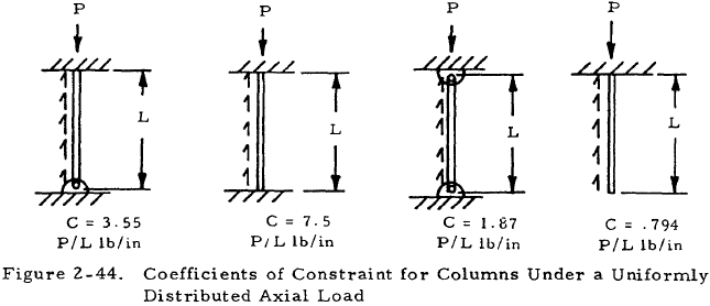
Columns subjected to distributed axial loads may be treated by formulas developed for end leaded columns if a coefficient of constraint is used that takes into account both the load condition and end fixities. Figure 2-44 shows columns under a uniformly distributed axial load of P/L lbs/in with various end restraints and their corresponding coefficients of constraint. The values P, L, and C are used in the formulas for end loaded columns.
2.3.1.6 Sample Problem - Concentrically Loaded Long Columns in Bending
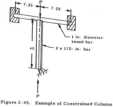
Given: The concentrically loaded rectangular bar shown in Figure 2-45 is fixed at one end and attached to a round bar at the other end. Both bars are made of steel for which E = 30×106 psi and G = 11.5×10⁶ psi.
Find: Pcr
Solution: From elementary strength of materials, θ = TL/IpG for a torsion bar. In effect, there are two 7.25-in -long bars attached to the end of the column so that the equivalent torsional spring constant is
$$ \mu = 2 { T \over \theta } = { 2 J G } \over L $$Substituting the appropriate values into the expression for μ gives
The column may now be redrawn as Figure 2-46.

From Figure 2-38, we find that C = 1.88. Solving Equation (2-2) for L' gives
$$ L' = { L \over \sqrt{C} } = { 40 \over \sqrt{1.88} } = 29.2 ~\text{in} $$The radius of gyration of the bar is
$$ \sqrt{I/A} = \sqrt{ {2(0.5)^2 \over 12} / 2(0.5) } = 0.144 ~\text{in} $$The slenderness ratio is
$$ { L' \over \rho } = { 29.2 \over 0.144 } = 203 $$From Section 2.3.1.11.7, it is found that a steel column for which L/ρ is greater than 120 is a long column. Thus, the Euler formula, Equation (2-1), becomes
$$ P_{cr} = { A \pi^2 E \over (L' / \rho)^2 } $$Substituting the values for the given column into this equation gives
$$ P_{cr} = { (0.5 \times 2) \pi^2 (30 \times 10^6) \over 203^2 } = 7,200 ~\text{lb} $$In general, a column such as this must also be checked for buckling in the plane through the bar and the column. In this case, however, the column will not fail by this mode.
2.3.1.7 Bending Failure of Eccentrically Loaded Long Columns
A theoretically correct formula that holds for eccentrically loaded columns is the secant formula:
In this formula, P, A, ρ, L, C, and E are defined as before, and e is the eccentricity of the load. The distance between the central axis and the concave side of the loaded column is designated as c. In the case of a long eccentrically loaded column, Fcol may be taken to be the value of Pcr/A found from the Euler formula in Section 2.3.1.3. If a factor of safety, FS, is applied, the corresponding formula for allowable load, Pa, becomes
The secant formula may also be used for short columns by finding Fcol differently as will be shown in the material on short columns.
All physical columns have some accidental initial curvature due to imperfections and some eccentricity of loading. In these cases, an equivalent eccentricity may be used to approximate the effects of the imperfections. Data may also be found for the equivalent eccentric ratio which is the ec/ρ2 term in the secant formula. Values for these may be found in Section 2.3.1.8.
The secant formula applies when the eccentricity is in the plane of the bending.
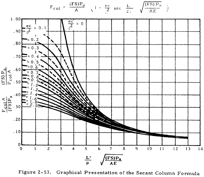
Unfortunately, the secant formula is difficult to solve and must be solved by either trial and error or charts.
Need a Column Buckling Calculator?
Try this column buckling calculator.
- buckling analysis of long and intermediate-length columns loaded in compression
- loading can be either central or eccentric
2.3.1.8 Equivalent Eccentricity for Imperfect Columns
As was mentioned previously, no column is perfectly straight and concentrically loaded. In order to allow for these initial imperfections in a column whose loads are concentrically applied, an equivalent eccentricity of loading may be assumed. The column may then be treated by methods used for an eccentrically loaded column.
Opinion is divided as to whether the equivalent eccentricity assumed for imperfections is dependent upon or independent of the length of a column. If we assume that it is independent of column length, an equivalent eccentric ratio ec/ρ2 ranging from 0.1 to 0.25 may be used. The mean value of such an eccentric ratio is approximately equal to 0.2. We may also assume that the equivalent eccentricity, e, is proportional to the effective length of the column. If this procedure is used, e may be taken to be equal to KL where K is a constant. Values of K ranging from 0.001 to 0.0025 may be used with the latter yielding conservative results.
2.3.1.9 Sample Problem – Long Eccentrically Loaded Columns and Equivalent Eccentricity
Given: The round column shown in Figure 2-47 with nominally concentric loading.

Find: The column diameter, D, for a factor of safety of 1.5, considering the initial imperfections of the column.
Solution: For a round section, I = πD4/64 and A = πD2/4. Thus, \(\rho = \sqrt{I/A} = D/4\). Since the column is pin ended, L = L' = 50 in. Try D = 1.215.
$$ { L' \over \rho } = { 50 \over 1.215/4 } = 164.5 $$According to Section 2.3.1.11.7, steel columns for which L'/ρ is greater than 120 may be treated as long columns. Thus Fcol in the secant formula may be found by the Euler formula:
$$ F_{col} = { \pi^2 E \over (L'/\rho)^2 } = { \pi^2 (30 \times 10^6) \over (164.5)^2 } = 10,950 ~\text{psi} $$The secant formula, Equation (2-4), may now be written as
$$ \begin{eqnarray} { (FS) P_a \over A } &=& { F_{col} \over 1 + {ec \over \rho^2} \sec{ \left[ {L' \over 2 \rho} \sqrt{ (FS) P_a \over AE} \right] } } \nonumber \\ &=& { 10,590 \over 1 + {ec \over \rho^2} \sec{ \left[ {L' \over 2 \rho} \sqrt{ (FS) P_a \over AE} \right] } } \end{eqnarray} $$According to Section 2.3.1.8, equivalent eccentric ratio due to initial imperfections is between 0.1 and 0.25. To be on the conservative side, use an equivalent eccentric ratio of 0.25. Substituting this and column parameters into the secant formula, the expression below is obtained.
or 6450 = 6450
Thus, the original guess of D = 1.215 was correct. If this were not true, different values of D would have to be chosen until one was found that would make both sides of the secant formula equal.
2.3.1.10 Bending Failure of Short Columns
In the previous discussion of long columns, it was assumed that the column material was in the elastic range at the time of buckling. This assumption, however, is not true for columns having an effective slenderness ratio of less than a certain critical value for a given material. This value of the critical effective slenderness ratio, L'/ρ, is discussed in Section 2.3.1.11.7. Since the Euler formula no longer applies for short columns, one of the formulas used to fit short column data must be used to treat them.
2.3.1.11 Bending Failure of Concentrically Loaded Short Columns
Several formulas are available to treat short columns. These have no theoretical justification as did the Euler formula, but fit column data to a degree of accuracy depending upon the material and column parameters. The equations most commonly used for short columns are the tangent modulus, Johnson Parabolic, and straight-line equations.
2.3.1.11.1 Tangent Modulus Equation
If the slenderness ratio of a column is low enough that some of its fibers are no longer in the elastic range at the time of failure, the Euler formula no longer holds. However, this case may be treated by defining a tangent modulus of elasticity, Et to be the slope of the stress-strain curve at a given point. This tangent modulus of elasticity may then be substituted for the modulus of elasticity in the Euler equation to obtain the tangent modulus equation (modified Euler equation).
Since Et is equal to E in the elastic range, the tangent modulus equation reduces to the Euler equation for long columns and is thus valid for both long and short columns.
The value of stress at which Et is found is the maximum stress in the column. In the case of a concentrically loaded column, this is equal to P/A. Since Et is a function of loading, the tangent modulus equation must be solved by trial and error if Et is found from stress-strain diagrams or tables.
The tangent modulus equation has been solved for a number of different materials and these solutions are shown in Section 2.3.1.1.
The main disadvantage of the previously described procedure for solving the tangent modulus equation is the trial and error method required. This disadvantage may be eliminated if an equation for the stress-strain curve is available. Such an equation is the Ramberg-Osgood equation,
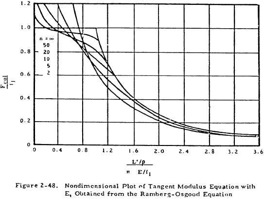
$$ \varepsilon = \sigma + {3 \over 7} ~\sigma^n $$Here, ϵ = Ee/f1 and σ = fc /f1 where e is the strain, fc is the compressive stress, and f1 is the stress at which the slope of a line from the origin to a point on the stress-strain curve is 0.7. E and n are constants determined experimentally for a given material. The Ramberg-Osgood equation may be used to obtain the following expression for the tangent modulus of elasticity.
This expression may in turn be substituted into the tangent modulus equation with fc equal to Fcol to obtain
In the case of a column under concentric loading, Fcol is equal to P/A. A nondimensional plot of this equation is shown in Figure 2-48. Values of n, f1 and E that are needed for the Ramberg-Osgood equation are shown in Table 2-2.
| Material | E, ksi | n | f1, ksi |
|---|---|---|---|
| Aluminum Alloys | |||
| 24 S-T Sheet | 10,700 | 10 | 41 |
| 24 S-T Extrusion | 10,700 | 10 | 37 |
| 75 S-T Extrusion | 10,500 | 20 | 71 |
| Clad 2024-T3 Longitudinal | 10,000 | 10 | 38.1 |
| Clad 2024-T4 Longitudinal | 10,000 | 15 | 36.5 |
| Steel | |||
| Normalized | 29,000 | 20 | 75 |
| Ftu = 100,000 | 29,000 | 25 | 80 |
| Ftu = 125,000 | 29,000 | 35 | 100 |
| Ftu = 150,000 | 29,000 | 40 | 135 |
| Ftu = 180,000 | 29,000 | 50 | 165 |
|
Titanium 6Al-4V Bar Stock, Longitudinal Ftu = 145 ksi at room temp, 1/2 hr exposure to temperature |
|||
| at room temperature | 17,500 | 10 | 164 |
| at 500°F | 16,000 | 17 | 108 |
| at 700°F | 15,000 | 10 | 93.4 |
| at 900°F | 13,800 | 9 | 85.7 |
One great advantage of using the Ramberg-Osgood relation is that the necessary constants may be obtained for new materials without extensive testing.
In general, the tangent modulus theory will yield conservative results. However, this theory yields values for the critical load that are too high for very short columns for which Et may be less than 0.2 at failure.
2.3.1.11.2 Sample Problem - Use of Tangent Modulus Equation for Concentrically Loaded Short Columns
Given: The 1-in. square concentrically loaded column shown in Figure 2-49.
Find: The maximum value of P by using the tangent modulus equation, with Et obtained from the Ramberg-Osgood relation.

Solution: Ultimately, Equation (2-7) must be solved. This equation is shown graphically in Figure 2-48. From Table 2-2, find E = 10.7 x 10⁶ psi, n = 10, and f1 = 37,000 psi for the given material. Consulting Section 2.3.1.4, find that C = 2.05 for the given end constraints. Solving Equation (2-2), find that L' = L/√C. In this case,
$$ L' = {15 \over \sqrt{2.05}} = 10.55 ~\text{in} $$For a square, I = b4/12 and A = b2.
$$ \rho = \sqrt{I \over A} = \sqrt{b^2 \over 12} $$In this case,
$$ \rho = \sqrt{1 \over 12} = 0.289 $$Thus,
$$ { L' / \rho \over \pi \sqrt{E / f_1} } = { 10.55/0.289 \over \pi \sqrt{ 10.7 \times 10^6 / 3.7 \times 10^4 } } $$From Figure 2-48,
$$ { F_{col} \over f_1 } = 0.88 $$Thus,
$$ F_{col} = {P_{cr} \over A} = 0.88 ~f_1 $$ $$ P_{cr} = 0.88 ~A ~f_1 = 0.88 (1) (37,000) $$ $$ P_{cr} = 32,600 ~\text{lb} $$Need a Column Buckling Calculator?
Try this column buckling calculator.
- buckling analysis of long and intermediate-length columns loaded in compression
- loading can be either central or eccentric
2.3.1.11.3 Reduced Modulus Equation
An equation that is theoretically more correct than the tangent modulus equation is the reduced modulus equation. In this case, a reduced modulus of elasticity, Er, is used to replace E in the Euler equation. This reduced modulus is a value between E and Et, one suggested value being
It can be seen from this equation that Er approaches E as Et approaches E so that the reduced modulus equation reduces to the Euler equation for long columns as does the tangent modulus equation.
The reduced modulus equation is accurate for specimens in which extreme care in manufacturing and testing is used but yields high values of critical load for other columns. The more conservative tangent modulus equation is preferred to the reduced modulus equation for this reason as well as for its greater simplicity.
2.3.1.11.4 Johnson-Euler Equation
For many materials a parabola may be used to fit column test data in the short column range. The equation of such a parabola may be written as
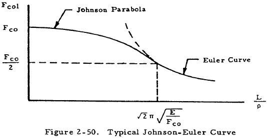
where Fco and K are constants chosen to fit the parabola to test data for a particular material. The Johnson-Euler column curve consists of the Euler curve for high L'/ρ ratios combined with a parabola that is tangent to this curve and covers short column ranges. If Equation (2-9) is adjusted so that it is tangent to the Euler curve, we obtain the Johnson equation
Here, Fcol is the maximum column stress which is given as P/A for concentrically loaded long columns and by more complicated formulas for eccentrically loaded columns. The single experimentally determined constant, Fco, is called the column yield stress but has little physical significance for columns with stable cross sections since very short columns for which L'/ρ is less than approximately 12 fail by block compression. In cases where local crippling and primary bending failure interact, Fco may be taken to be equal to the section crippling allowable. This case will be discussed more extensively in Section 2.3.2. A typical Johnson-Euler curve is shown in Figure 2-50. The coordinates that are marked show the point of tangency between the Johnson parabola and the Euler curve. Thus, the critical effective slenderness ratio separating long columns from short columns is \( \sqrt{2} ~\pi \sqrt{E/F_{co}} \) for the Johnson-Euler curve.
The main advantages of the Johnson-Euler curve are its ability to fit data when there is an interaction between crippling and primary bending failure and simplicity of computation. For columns having stable cross sections, one of the other short column curves is normally perferred.
2.3.1.11.5 Straight Line Equation
Short column curves for most aluminum alloys and several other materials are best represented by straight lines. A typical straight line is shown in Figure 2-51.
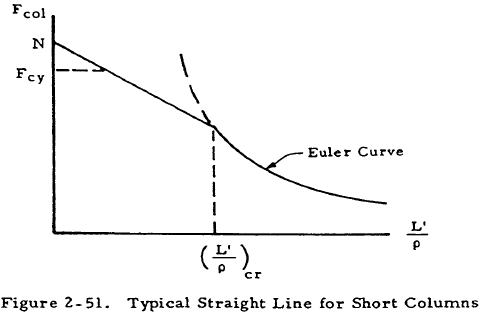
As can be seen from Figure 2-51, the straight line is not necessarily tangent to the Euler curve as is the case for the Johnson parabola but this is often the case. The straight line shown may be given by the equation
where N and M are constants chosen to best fit column data for a given material. As in the case of the Johnson parabola, this straight line does not always hold for very short columns that fail by block compression so it is cut off at Fcy as shown in the figure.
The critical effective slenderness ratio may be found by equating Fcol as found by the Euler formula to that value as found by Equation (2-11). This procedure involves solving a cubic equation and will not be presented here since values of the critical slenderness ratio are tabulated in Table 2-3.
Values of the constants N, M and the corresponding critical slenderness ratio (L'/ρ)cr are available for a large number of aluminum alloys and manufacturing processes. These values are shown in Table 2-3.
2.3.1.11.6 Sample Problem - Use of Straight Line Equation for Concentrically Loaded Short Columns
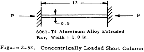
Given: The concentrically loaded rectangular bar shown in Figure 2-52.
Find: The critical load, Pcr.
Solution: Since the column is made of aluminum alloy, a straight-line equation should be accurate if the column is short. From Section 2.3.1.4, C = 4 for columns having both ends fixed. Since C = (L/L')2, L' = L/2. The radius of gyration,
$$ \rho = \sqrt{ I \over A } = \sqrt{ { bh^3 \over 12 } / bh } $$Thus,
$$ \rho = \sqrt{ h^2 \over 12 } = \sqrt{ (0.5)^2 \over 12 } = 0.144 $$ $$ { L' \over \rho } = { 6 \over 0.144 } = 41.6 $$From Table 2-3, we find that (L'/ρ)cr = 128 for this material. Since L'/ρ is less than this critical value, a straight line equation may be applied. Substituting the values of N and M, given for 6061-T4 extruded bars in Table 2-3, into Equation (2-11), we obtain
$$ F_{col} = \left[ 15.7 - 0.074 \left({ L' \over \rho }\right) \right] ~\text{ksi} $$Thus,
$$ { P_{cr} \over A } = F_{col} = \left[ 15.7 - 0.074 (41.6) \right] ~\text{ksi} $$or
$$ \begin{eqnarray} P_{cr} &=& 12.55 ~A = 12.55(0.5) = 6.27 ~\text{kip} \nonumber \\ P_{cr} &=& 6,270 ~\text{lb} \end{eqnarray} $$2.3.1.11.7 Critical Effective Slenderness Ratio
So far, long columns and concentrically loaded short columns have been discussed. It has been mentioned that a long column is one for which the Euler equation holds in the concentrically loaded case. This equation holds for columns having an effective slenderness ratio greater than a value called the critical effective slenderness ratio of the column. In some cases, this critical effective slenderness ratio need not be determined. For example, the tangent modulus equation, reduced modulus equation, or plotted data may be applied to either long or short columns. In other cases, this ratio must be known in order to decide which of two equations is to be applied to a column. A critical effective slenderness ratio must be found if the Johnson-Euler or a straight line equation is to be used.
The critical effective slenderness ratio is, in general, a function of the column material. If the Johnson-Euler formula is to be used, we obtain
as our critical effective slenderness ratio. If a straight line formula is to be used, the critical slenderness ratio is the slenderness ratio for which the Euler curve and the straight line either intersect or are tangent. A general formula is not given here since the critical effective slenderness ratio for each straight-line equation whose parameters are given in Table 2-3 is also given there.
In general, a steel column having a critical effective slenderness ratio of greater than 120 or an aluminum column having one of greater than 220 may be immediately treated as a long column. Columns having lower effective slenderness ratios must be checked by Equation (2-12) or Table 2-3 or treated by a method applicable to both long and short columns. If Equation (2-12) is used, Fco may be assumed to be approximately equal to Fcy for a rough estimate of L'/ρ.
2.3.1.11.8 Bending Failure of Eccentrically Loaded Short Columns
The column formulas in the previous section do not apply if a column is eccentrically loaded or if initial imperfections are large enough to have the effect of an appreciable initial eccentricity. In such cases, either another formula must be used or adjustments must be made to existing equations.
The secant formula that was given in Section 2.3.1.7 may also be applied to short columns if its parameters are chosen correctly. This equation is given again below for convenient reference.
Fcol is the maximum fiber stress at failure as before. Different references suggest various ways of choosing Fcol. Reasonable results may be obtained for very short columns if Fcol is assumed to be equal to the compressive yield point for steel or the compressive yield stress for light alloys. In the case of intermediate length columns, Fcol should be taken to be the stress obtained from one of the formulas for a concentrically loaded short column. If the formula used for this purpose is the tangent modulus equation, E should be replaced by Et in the secant equation. The secant equation must either be solved by trial and error or through use of a chart such as that shown in Figure 2-53.
Unfortunately, the secant formula is inconvenient for computation. A simpler approach may be used if the column deflection is small compared to the eccentricity of loading. This assumption is true for very short columns and to a lesser extent for intermediate length columns.
Using the previously mentioned assumption, the basic design equation for an eccentrically loaded short column becomes
Here Fcol is the maximum column stress as computed from one of the equations for a short concentrically loaded column.
A more refined design equation based on the assumption of a small column deflection relative to the eccentricity of loading is
where Facol is the working concentrically loaded column stress and Fb is the working compressive stress in bending.
In conclusion, the secant formula is theoretically more correct and yields better results for eccentrically loaded short columns. However, due to the difficulty of applying this formula, Equation (2-14) or (2-15) may at times be applied, especially for shorter columns.
2.3.1.11.9 Sample Problem - Eccentrically Loaded Short Column in Bending
Given: The eccentrically loaded round column shown in Figure 2-54.

Find: The allowable load, Pa, if a factor of safety of 1.3 is used. Use (a) the secant modulus equation, and (b) Equation (2-14).
Solution: (a) The secant modulus equation may be written as
$$ { (FS) P_a \over A } = { F_{col} \over 1 + {ec \over \rho^2} \sec{ \left[ {L' \over 2 \rho} \sqrt{ (FS) P_a \over AE} \right] } } $$Since the column is made of aluminum alloy, the straight-line column Equation (2-11) may be used to find Fcol if it is short. From Table 2-3, find that B, D, and (L'/ρ)cr for this material are 15,700 lb, 15 lb, and 128 respectively. Thus,
$$ F_{col} = 15,700 - 15 \left({ L' \over \rho }\right) $$Since the column is pin ended, L' = L = 12 in. For a circular section, ρ = D/4 = 0.25. Inserting these values into the above equation gives Fcol = 14,980 psi. Since L'/ρ is equal to 48 and (L'/ρ)cr is equal to 128, the assumption of a short column is valid. All of the parameters for the secant formula are now known except Pa. Inserting these values in the secant modulus equation gives
Simplifying this gives
$$ P_a = { 9,090 \over 1 + 0.8 \sec{[ 0.00975 \sqrt{P_a} ]} } $$Try Pa = 5,000 lb. Substituting this value, we find that it solves this equation. Thus, Pa = 5,000. If our original guess was incorrect, other values of Pa would have to be tried until a value was found that solved the equation.
(b) Inserting the equation for Fcol from part (a) into Equation (2-14) gives
$$ { 15,700 - 15 (L'/\rho) \over FS } = {P \over A} + {P_{ec} \over I} $$or
$$ { 15,700 - 15 (12/0.25) \over 1.3 } = {P \over \pi/4} + {P (0.1)(0.5) \over \pi/64} $$Solving this for P gives Pcr = 6,540 lb. Notice that although this procedure eliminates the trial and error methods used with the secant equation, it yields less conservative results.
Need a Column Buckling Calculator?
Try this column buckling calculator.
- buckling analysis of long and intermediate-length columns loaded in compression
- loading can be either central or eccentric
2.3.1.12 Torsional Failure of Simple Columns
The previous sections discussed the failure of long and short columns by bending. It was assumed throughout this treatment that the sections of the column are translated but not rotated as it fails. However, primary failure may occur at loads lower than those predicted in the section on bending failure if the sections should rotate as well as translate as shown in Figure 2-55.
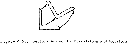
In general, columns whose cross sections have a low torsional rigidity, GJ, must be examined for torsional instability. Columns having closed sections or solid ones, such as round or square sections, have such a high torsional rigidity that there is little possibility of them failing by torsional instability. However, torsional instability must be considered in the case of columns composed of thin sections. Failure by twisting is unlikely for flanged columns whose cross sections are symmetrical about a point such as I, H, and Z sections. Twisting-type failures are most apt to occur in the case of torsionally weak sections that are unsymmetrical or have only one axis symmetry such as angles, tees, and thin-walled channels.
The basic equation for a column that fails by a combination of bending and twisting gives the critical stress as
In this case, CBT is a sectional property defined below and the parameters are defined as usual.
The torsion bending constant is dependent upon the axis of rotation and defined as
where
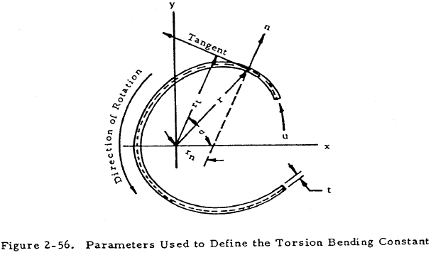
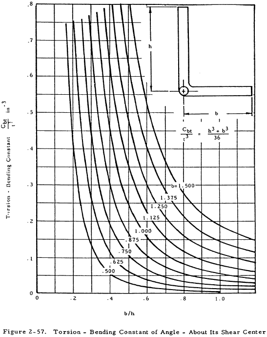
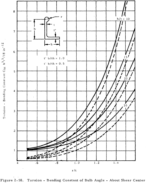
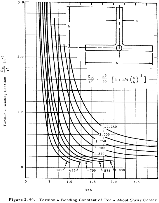
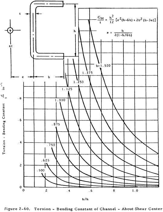
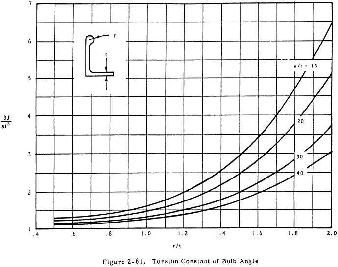
The parameters used above are shown on an arbitrary cross section in Figure 2-56. Values of the torsional bending constant are given in graphical form for various cross sections in Figures 2-57 through 2-60. The torsion constant, J, may be obtained in Figures 2-61 for bulb angles or from the following equation for formed sections:
Here, s is the developed length of the median line.
If a column is not attached to a sheet, the twisting failure is by rotation of sections about shear center of cross section. In this case, Ip and CBT are taken about this shear center. If the column is attached to a sheet, sections may be assumed to rotate about a point in the plane of the sheet. This procedure gives rough results but unfortunately littLe specific information is available on this subject. In general, columns are stronger when they are used as stiffeners than when they stand free. However, a column having an unsymmetrical cross section may be weaker when it is attached to a sheet.
2.3.1.13 Sample Problem- Torsional Failure of Simple Columns
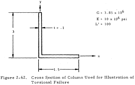
Given: A column with cross section and material properties as shown in Figure 2-62.
Find: Fcol for failure by a combination of bending and twisting.
Solution: Since t is small, the shear center may be assumed to be at the corner of the angle.
The polar moment of inertia about the shear center is given by
$$ I_p = I_x + I_y $$or
From Equation (2-19)
$$ J = { st^3 \over 3 } = { 4.5 (0.1)^3 \over 3 } = 1.5 \times 10^{-3} $$From Figure 2-57,
Inserting these values into Equation (2-16) gives
Thus, Fcol = 6,419 psi.
