Simple Beam Bending
This page provides the sections on simple beam bending from the "Stress Analysis Manual," Air Force Flight Dynamics Laboratory, October 1986.
Other related chapters from the Air Force "Stress Analysis Manual" can be seen to the right.
- Simple Beam Bending
- Shear Web Beam Bending
- Partial Tension Beam Bending
- Beam Forces & Moments
- Beam Columns
- Beam Torsion
Nomenclature
| A | = | cross-sectional area |
| b | = | width of section |
| c | = | distance from neutral axis to extreme fiber |
| E | = | modulus of elasticity |
| Fty | = | yield stress in tension |
| fb | = | calculated primary bending stress |
| fcr | = | calculated critical compressive stress |
| G | = | modulus of elasticity in shear |
| h | = | height or depth |
| I | = | moment of inertia |
| J | = | torsion constant |
| L | = | length |
| L' | = | effective length of beam |
| M | = | applied bending moment |
| Mcr | = | critical moment |
| Mfp | = | fully plastic bending moment |
| My | = | bending moment at the onset of yielding |
| P | = | applied concentrated load |
| Q | = | statical moment of cross section, \( \int_{A_1} y ~dA \) |
| q | = | shear flow |
| s | = | distance from centroidal axis to point of application of load |
| tf | = | flange thickness |
| tw | = | web thickness |
| V | = | shear force |
| x, y, z | = | rectangular coordinates |
| y | = | deflection of beam due to bending |
| ρ | = | radius of gyration |
| θ | = | slope of beam |
1.3.1 Simple Beams in Bending
Simple beams in elastic and plastic bending are treated in Sections 1.3.1.1 and 1.3.1.3, respectively, while the possibility of lateral instability of deep beams in bending is treated in Section 1.3.1.5.
1.3.1.1 Simple Beams in Elastic Bending
This section treats simple beams in bending for which the maximum stress remains in the elastic range.
The maximum bending stress in such a beam is given by the formula
while the shear flow is given by
where \( Q = \int_{A_1} y~dA \). The use of these equations is illustrated in Section 1.3.2.2.
The vertical and angular displacements of a simple beam in elastic bending are given by Equations (1-3) and (1-4), respectively, where A and B are constants of integration.
Need a Beam Calculator?
Try this beam calculator.
- Calculates stresses and deflections in straight beams
- Builds shear and moment diagrams
- Can specify any configuration of constraints, concentrated forces, and distributed forces
1.3.1.2 Sample Problem - Simple Beams in Elastic Bending
Given: The cantilever beam shown in Figure 1-1.
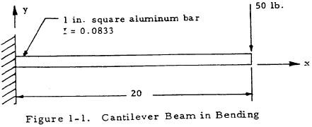
Find: The maximum bending and shear stresses.
Solution: From the equations of statics, the shear and moment diagrams in Figure 1-2 may be obtained.
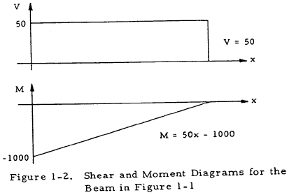
Since c and I are constant along the beam, the maximum bending stress occurs at the point of maximum bending moment; and from Equation (1-1),
$$ f_b = { Mc \over I } = { -1000(0.5) \over 0.0833 } = 6,000~ \text{psi} $$Q may be computed at a distance y1 from the neutral axis by considering the beam cross section shown in Figure 1-3:
$$ Q = \int_{A_1} y~ dA = \int_{y_1}^1 y ~(1) ~dy = {1 \over 2} - { y_1^2 \over 2 } $$Q is maximum at y1 = 0 where Q = 1/2. Thus, the maximum shear flow occurs at the neutral axis and is given by Equation (1-2) as
$$ q = { VQ \over I } = { 50 (0.5) \over 0.0833 } = 300 ~\text{ lb/in } $$The maximum shear stress is thus,
$$ { 300 ~\text{ lb/in } \over 1 ~\text{in} } = 300~ \text{ lb/in }^2 $$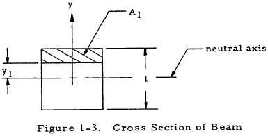
Need a Beam Calculator?
Try this beam calculator.
- Calculates stresses and deflections in straight beams
- Builds shear and moment diagrams
- Can specify any configuration of constraints, concentrated forces, and distributed forces
1.3.1.3 Simple Beams in Plastic Bending
In some cases, yielding of a beam in bending is permissible. If the beam material may be considered to be elastic-perfectly plastic, the bending moment at failure is given by
where My is the moment that causes initial yielding of the extreme fibers and K is the shape factor given in Table 1-1.
| Section |

|

|

|

|

|

|

|
| K | 1.0 | 1.5 | 2.0 | 1.7 |
$$ 1.27 \left( 1 - {t \over r} \right) $$
|
$$ { 32 D_o (D_o^3 - D_i^3) \over 3\pi (D_o^4 - D_i^4) } $$
|
$$ {3h \over 2} \left({ bh^2 - 2 b_1 h_1^2 \over b h^3 - 2 b_1 h_1^3 }\right) $$
|
1.3.1.4 Sample Problem - Simple Beams in Plastic Bending
Given: The simply supported beam shown in Figure 1-4.
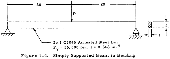
Find: The load, P, that causes fully plastic bending.
Solution: Rearranging Equation (1-1) and replacing the bending stress with the yield stress gives
$$ M_y = { F_y ~I \over c } = { 55000 (0.666) \over 1.0 } = 36,600 ~\text{in/lb} $$Inserting the value of K from Table 1-1 into Equation (1-5) gives
$$ M_{fp} = K ~M_y = 1.5 (36,600) = 54,900 ~\text{in/lb} $$From statics, the maximum moment on the bar is 10P. Thus, for fully plastic bending,
$$ P = { M_{fp} \over 10 } = 5,490 ~\text{lb} $$1.3.1.5 Intoduction to Lateral Instability of Deep Beams in Bending
Beams in bending under certain conditions of loading and restraint can fail by lateral buckling in a manner similar to that of columns loaded in axial compression. However, it is conservative to obtain the buckling load by considering the compression side of the beam as a column since this approach neglects the torsional rigidity of the beam.
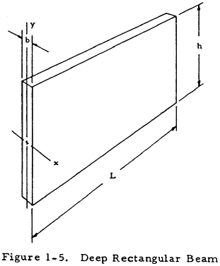
In general, the critical bending moment for the lateral instability of the deep beam, such as that shown in Figure 1-5, may be expressed as
where J is the torsion constant of the beam and K is a constant dependent on the type of loading and end restraint. Thus, the critical compressive stress is given by
where c is the distance from the centroidal axis to the extreme compression fibers. If this compressive stress falls in the plastic range, an equivalent slenderness ratio may be calculated as
The actual critical stress may then be found by entering the column curves of Chapter 2 at this value of (L'/ρ). This value of stress is not the true compressive stress in the beam, but is sufficiently accurate to permit its use as a design guide.
Need a Beam Calculator?
Try this beam calculator.
- Calculates stresses and deflections in straight beams
- Builds shear and moment diagrams
- Can specify any configuration of constraints, concentrated forces, and distributed forces
1.3.1.6 Lateral Instability of Deep Rectangular Beams in Bending
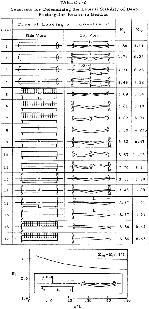
The critical moment for deep rectangular beams loaded in the elastic range loaded along the centroidal axis is given by
where Ku is presented in Table 1-2, and b, h, and L are as shown in Figure 1-5. The critical stress for such a beam is
where Ku is presented in Table 1-2.
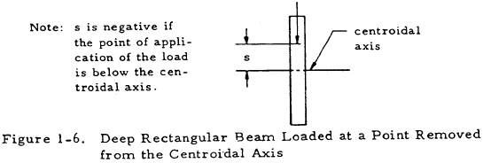
If the beam is not loaded along the centroidal axis, as shown in Figure 1-6, a corrected value K'f is used in place of Kf in Equation (1-10). This factor is expressed as
where n is a constant defined below:
- For simply supported beams with a concentrated load at midspan, n = 2.84.
- For cantilever beams with a concentrated end load, n = 0.816.
- For simply supported beams under a uniform load, n = 2.52.
- For cantilever beams under a uniform load, n = 0.725.
Need a Beam Calculator?
Try this beam calculator.
- Calculates stresses and deflections in straight beams
- Builds shear and moment diagrams
- Can specify any configuration of constraints, concentrated forces, and distributed forces
1.3.1.7 Lateral Instability of Deep I Beams
Figure 1-7 shows a deep I beam.
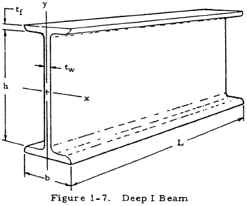
The critical stress of such a beam in the elastic range is given by
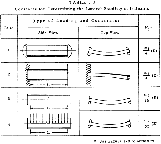
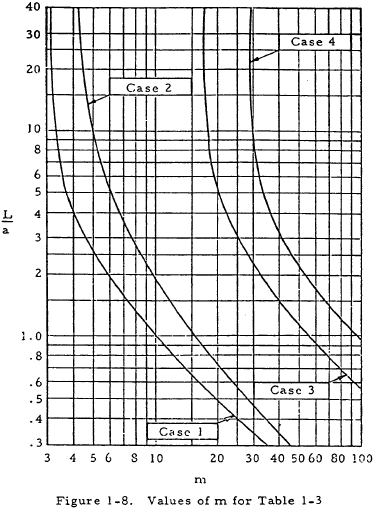
where KI may be obtained from Table 1-3, and a is given by
where J is the torsion constant of the I beam. This constant may be approximated by
This method can be applied only if the load is applied at the centroidal axis.
