Analysis of Complex Columns
This page provides the sections on the analysis of complex columns from the "Stress Analysis Manual," Air Force Flight Dynamics Laboratory, October 1986.
Other related chapters from the Air Force "Stress Analysis Manual" can be seen to the right.
- Analysis of Simple Columns
- Column Data
- Constants for Straight Line Equation
- Crippling of Columns
- Analysis of Complex Columns
Nomenclature
| A | = | area |
| E | = | modulus of elasticity |
| Et | = | tangent modulus of elasticity |
| Fcol | = | maximum fiber stress for primary failure of a column |
| f1 | = | stress at which the secant modulus of elasticity is equal to 0.7 |
| I | = | moment of inertia |
| L | = | length |
| n | = | empirical constant in Ramberg-Osgood equation |
| P | = | axial load |
| Pcr | = | critical load |
| Pe | = | Euler critical load |
2.4 Complex Columns
The material in previous sections treated columns that have uniform cross sections and may be considered to be one piece. This section treats of stepped and tapered columns whose cross section varies as well as of latticed columns whose action varies from that of one-piece columns.
2.4.1 Stepped and Tapered Columns
Columns of variable cross section can be solved by numerical procedures. However, charts are available that vastly simplify the solution of stepped and tapered columns.
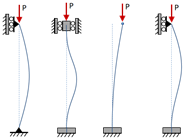
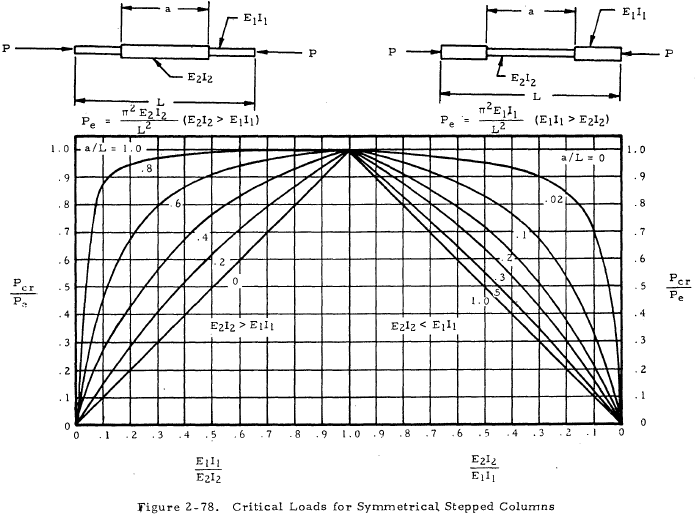
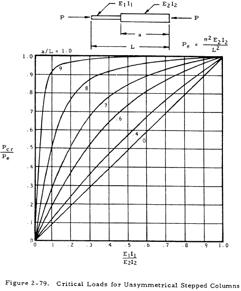
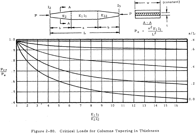
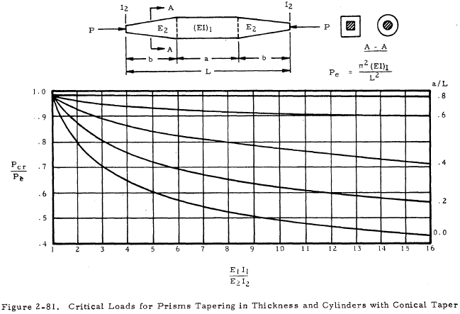
These charts are shown in Figures 2-78 through 2-81. The use of these charts in finding a critical load is self-explanatory except for the fact that the tangent modulus of elasticity, Et, must be used in place of E if the section is stressed beyond the proportional limit. Also, the coefficients of constraint that were discussed in Section 2.3.1.4 no longer hold for stepped or tapered columns. The columns shown in the charts have pinned ends.
2.4.2 Sample Problem - Stepped Column
Given: The concentrically loaded pin ended, stepped column shown in Figure 2-77.
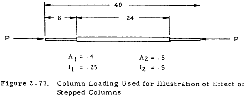
Find: The critical load Pcr·
Solution: Assume Pcr = 11,600 lb. Thus, Fcol.1 and Fcol.2 are equal to 11,600/0.4 psi and 11,600/0.5 psi, respectively. Equation (2-6) gives Et as
$$ E_t = { E \over 1 + 3/7 ~n \sigma^{n-1} } $$Since σ = fc /f1 where f is the compressive stress which, in this case, is Fcol,
$$ E_t = { E \over 1 + 3/7 ~n \left({ F_{col} \over f_1 }\right)^{n-1} } $$Inserting values of f1 and n from Figure 2-48 into this equation gives
$$ E_t = { 10.7 \times 10^6 \over 1 + 42.9 \left({ F_{col} \over 37000 }\right)^9 } $$Inserting the values of Fcol.1 and Fcol.2 into this equation gives
$$ E_{t.1} = 1.86 \times 10^6 ~\text{psi} $$and
$$ E_{t.2} = 6.55 \times 10^6 ~\text{psi} $$Thus
$$ { E_{t.1} I_1 \over E_{t.2} I_2 } = { 1.86 \times 10^6 (0.25) \over 6.55 \times 10^6 (0.50) } = 0.142 $$From Figure 2-78, Pcr/Pe, = 0.57 where
$$ P_e = { \pi^2 E_{t.2} I_2 \over L^2 } $$Thus,
$$ P_{cr} = P_e = { 0.57 \pi^2 (6.55 \times 10^6) (0.5) \over (40)^2 } $$or Pcr = 11,600 psi. The original guess is thus correct. If it were not, other values would have to be tried until the correct value was found.
Need a Column Buckling Calculator?
Try this column buckling calculator.
- buckling analysis of long and intermediate-length columns loaded in compression
- loading can be either central or eccentric
2.4.3 Latticed Columns
Although it is customary to assume that a latticed column acts as a single unit and develops the full strength of the section, a column is actually less stiff if the buckling occurs in a plane normal to that of the lacing. This fact is unimportant if a column is designed so that buckling occurs in a plane normal to that of the lacing, but it must be taken into account for columns that are laced on all sides.
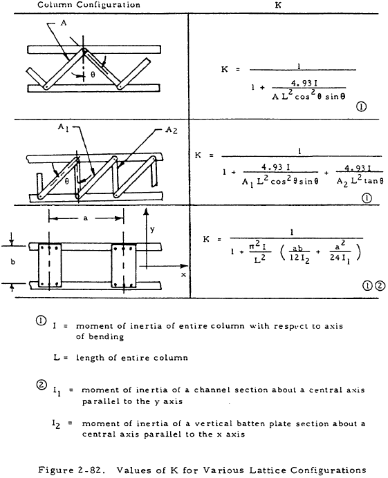
In order to take the effect of lacing into account, a reduced modulus of elasticity, KE, may be used in place of E in the equations for simple columns. Equations giving K as a function of column parameters are given in Figure 2-82 for various lattice configurations.
In designing latticed columns, care must also be taken to ensure that buckling of the individual members does not occur between points of attachment. In general, the slenderness ratio of a longitudinal member between points of attachment should be less than 40 or two-thirds of the slenderness ratio of the column as a whole, whichever is lower.
