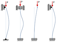
Crippling Failure of Columns
This page provides the sections on the analysis of crippling failure in columns from the "Stress Analysis Manual," Air Force Flight Dynamics Laboratory, October 1986.
Other related chapters from the Air Force "Stress Analysis Manual" can be seen to the right.
Nomenclature
| A | = | area |
| b | = | linear dimension as indicated in diagrams |
| C | = | coefficient of constraint = (L/L' )2 |
| E | = | modulus of elasticity |
| Fcc | = | allowable crippling stress |
| Fco | = | empirical constant in Johnson parabolic equation (column yield stress) |
| Fcol | = | maximum fiber stress for primary failure of a column |
| Fcy | = | compressive yield stress |
| h | = | height |
| I | = | moment of inertia |
| K | = | empirical constant |
| L | = | length |
| L' | = | effective length = L/√C |
| P | = | axial load |
| Pcc | = | crippling load |
| r | = | radius |
| t | = | thickness |
| μ | = | Poisson's ratio |
| ρ | = | radius of gyration = \( \sqrt{I/A} \) |
| Σ | = | summation |
2.3.2 Introduction to Crippling Failure of Columns
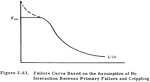
In the previous sections, the primary failure of simple columns was considered. However, if a column has thin sections, it may fail at a load well below the critical load predicted for primary failure. Thus, a column must, in general, be checked for both primary failure and crippling. Primary failure may be assumed to be independent of crippling effects, in which case, a failure curve such as that shown in Figure 2-63 may be used. The right-hand portion of the curve describes the stress required for primary failure of the column at various effective slenderness ratios. This curve is cut off at the crippling stress level by the flat portion to the left.
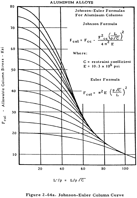
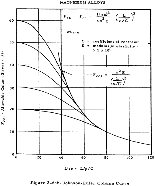
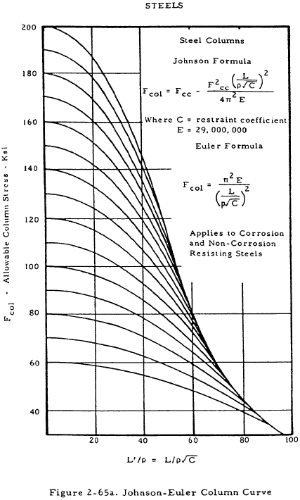
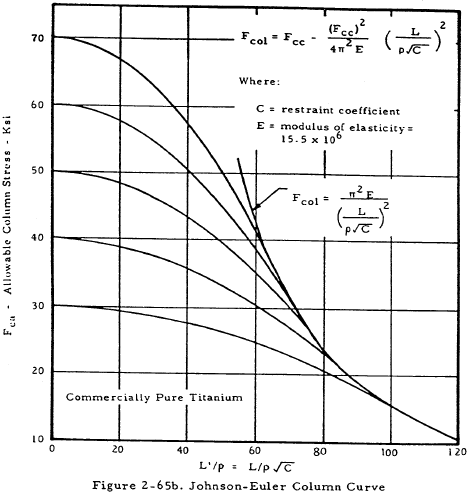
If the interaction between crippling and primary failure is to be taken into account, the constant Fco in the Johnson-Euler equation may be set equal to the crippling stress Fcc. Although this procedure is more correct, it also introduces added complications, and only works for columns having a crippling stress less than the primary failure stress as L'/ρ approaches zero. Figures 2-64 and 2-65 show sets of Johnson-Euler curves for various materials. The curve used in a given case is the one that intercepts the ordinate at the value of Fcc for that column.
Need a Column Buckling Calculator?
Try this column buckling calculator.
- buckling analysis of long and intermediate-length columns loaded in compression
- loading can be either central or eccentric
2.3.2.1 Crippling Stress of Round Tubes
Steel tubes for which the diameter-to-wall thickness ratio is less than 50 need not be checked for crippling. This gives us some general idea of the thinness required if a tube is to fail by crippling rather than by primary instability. A theoretically correct formula for the crippling stress of a tube is
where r is the mean radius and μ = Poisson's ratio. if μ is taken to be 0.3, as is the case for steel and aluminum alloys, we obtain
This equation, however, is extremely unconservative for small values of t/r and should only be used for approximations in the early stages of design.
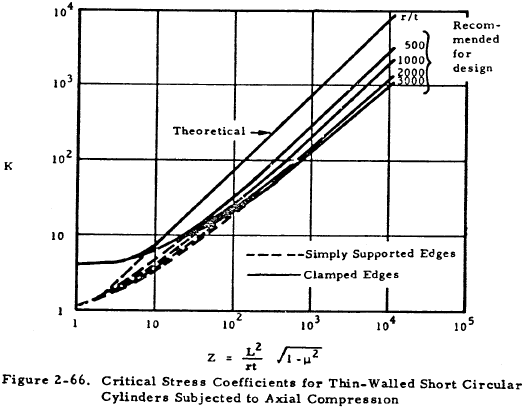
More conservative and accurate empirical methods are available for the treatment of tubular columns. If L/r is less than 0.75, use the equation
where the critical stress coefficient, K, is given in Figure 2-66.
If L/r is greater than 0.75, use the equation
where C is given in Figure 2-67.
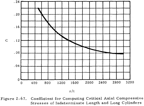
2.3.2.2 Sample Problem - Crippling Stress of Round Tubes
Given: The tubular aluminum column shown in Fignre 2-68.
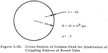
Find: The crippling stress if
(a) L = 5 in.
(b) L = 60 in.
Solution: (a) In this case, L/r < 0.75 so we may use Equation (2-22)
From Figure 2-66, K = 11. Substituting this value into Equation (2-22), we find that
$$ F_{cc} = { 2 K \pi^2 r \over L^2 t } = { 2 (11) \pi^2 (10) \over (5)^2 (0.02) } = 4,350 ~\text{psi} $$(b) If L = 60 in., L/r > 0.75 so that Equation (2-23) may be used
$$ {r \over t} = 500 $$From Figure 2-67, C = 0.22. Substituting this value into Equation (2-23), we find that
If the theoretically correct formula, Equation (2-20), is used for either of these two columns,
$$ F_{cc} = 0.605 { Et \over r } = 12,100 ~\text{psi} $$This value may be seen to be much greater than those obtained from the more accurate empirical formulas.
Need a Column Buckling Calculator?
Try this column buckling calculator.
- buckling analysis of long and intermediate-length columns loaded in compression
- loading can be either central or eccentric
2.3.2.3 Crippling Stress of Outstanding Flanges
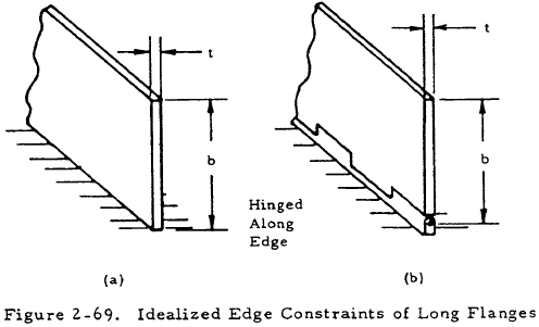
Two idealized cases of edge restraint of long flanges are shown in Figure 2-69. In case (a), the flange is fixed along its edge and the equation for its crippling stress is
The flange shown in (b) is hinged along its edge and the equation for its crippling stress is
A column flange is neither rigidly fixed nor hinged along its edge so its crippling stress lies between those given by Equations (2-24) and (2-25), the latter giving more conservative results.
2.3.2.4 Crippling Stress of Angle Elements and Complex Shapes
The basic design equations for the crippling stress and load of the angle section shown in Figure 2-70 are
and
Here b' is equal to (h+b)/2 as seen in Figure 2-69 and Ce is a constant dependent upon the fixity of the edges, as shown to the right of Figure 2-70.
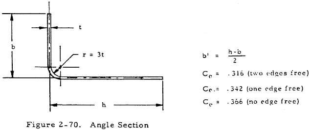
The area of this angle is given by
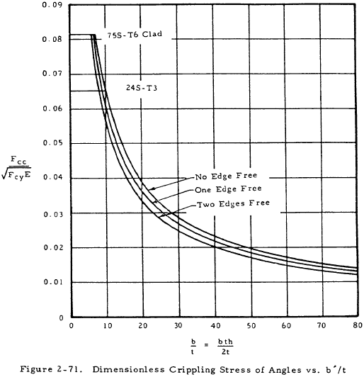
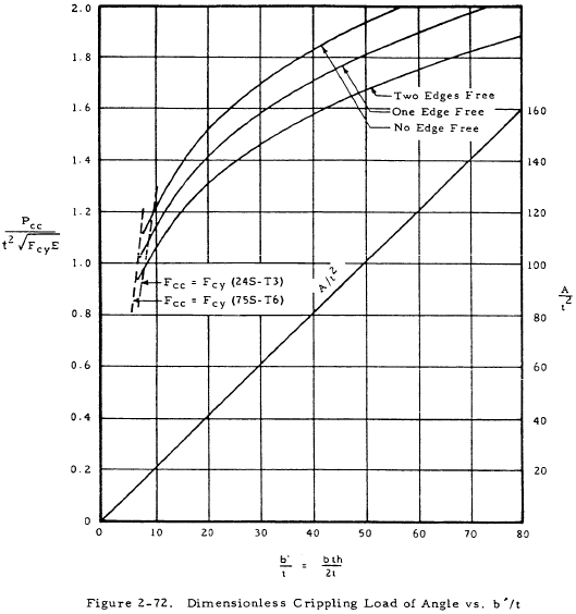
Nondimensional plots of Equations (2-26) and (2-27) are shown in Figures 2-71 and 2-72, respectively. These plots may be used to facilitate the solution of angle problems. It must be noted that Equations (2-26) and (2-27) have no significance when Fcc is greater than Fcy. These cutoffs are shown for two alloys in the following figures.
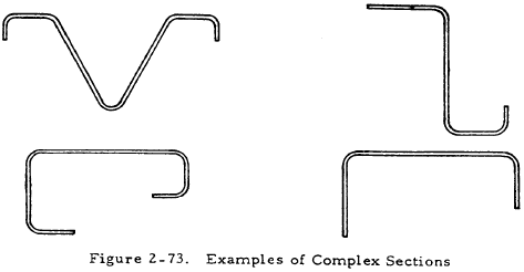
Many complex sections, such as those shown in Figure 2-73, may be treated by considering them to be composed of a number of angles. The crippling stress of these sections may be found by the following procedure: First, break the section up into a number of angles. Secondly, find the crippling load and area of each of the angles. Finally, find Fcc for the entire section from the following equation:
This procedure is illustrated in the following example.
2.3.2.5 Sample Problem- Crippling Stress of a Complex Shape
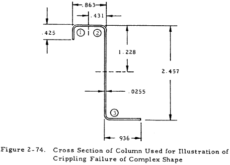
Given: Column with the cross sectional shape shown in Figure 2-74. It is composed of an aluminum alloy for which E = 107 psi and Fcy = 50 kips.
Find: The crippling stress Fcc·
Solution: This section may be broken into three angle sections as shown by the broken lines above. The calculation of the crippling load and area of each angle section is summarized in the table below:

The values of b and h in this table are as shown in Figure 2-70. The values of Pcc and A may either be found from Equations (2-27) and (2-28) or from Figure 2-72 which shows these equations in graphical form. The crippling stress may now be found from Equation (2-29) to be
Substituting the material properties into the above equation gives
Need a Column Buckling Calculator?
Try this column buckling calculator.
- buckling analysis of long and intermediate-length columns loaded in compression
- loading can be either central or eccentric
2.3.2.6 Crippling Stress of I Beams
Figure 2-75 shows an I section.
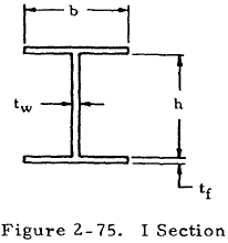
The crippling stress of a column of this shape is given by
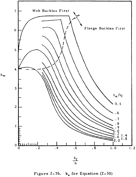
where kw is given in Figure 2-76.
