Beam Forces and Moments
This page provides the sections on beam forces and moments from the "Stress Analysis Manual," Air Force Flight Dynamics Laboratory, October 1986.
Other related chapters from the Air Force "Stress Analysis Manual" can be seen to the right.
- Simple Beam Bending
- Shear Web Beam Bending
- Partial Tension Beam Bending
- Beam Forces & Moments
- Beam Columns
- Beam Torsion
Nomenclature
| A | = | area of moment diagram |
| a | = | linear dimension |
| a | = | distance from the left end of a span to the centroid of its moment diagram |
| b | = | linear dimension |
| b | = | distance from the right end of a span to the centroid of its moment diagram |
| C | = | centroid of moment diagram |
| c | = | linear dimension |
| d | = | linear dimension |
| E | = | modulus of elasticity |
| I | = | moment of inertia |
| L | = | length |
| M | = | applied bending moment |
| P | = | applied concentrated load |
| R | = | reaction |
| W | = | concentrated transverse load |
| w | = | distributed transverse load |
1.3.4 Introduction to Reaction Forces and Moments on Beams Under Transverse Loading
Figure 1-30 shows a beam under transverse loading. Two equations of equilibrium may be applied to find the reaction loads applied to such a beam by the supports. These consist of a summation of forces in the vertical direction and a summation of moments. If a beam has two reaction loads supplied by the supports, as in the case of a cantilever beam or a beam simply supported at two points, the reaction loads may be found by the equilibrium equations and the beam is statically determinate. However, if a beam has more than two reaction loads, as in the case of a beam fixed at one end and either pinned or fixed at the other end, it is statically indeterminate and beam deflection equations must be applied in addition to the equations of statics to determine the reaction loads.

Section 1.3.4.1 presents a method for determining reaction loads on beams fixed at one end and pinned at another point, and Section 1.3.4.3 treats reaction loads for beams fixed at both ends. Beams on three or more supports are treated in Section 1.3.4.5.
Need a Beam Calculator?
Try this beam calculator.
- Calculates stresses and deflections in straight beams
- Builds shear and moment diagrams
- Can specify any configuration of constraints, concentrated forces, and distributed forces
1.3.4.1 Reaction Forces and Moments on Beams with One Fixed End and One Pinned Support
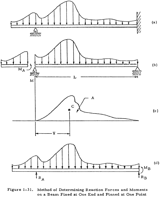
Figure 1-31(a) shows a uniform beam with one fixed and one pinned support. The following procedure may be used to determine the support reactions on such a beam if its stresses are in the elastic range.
- Split the beam at the pinned support as in Figure 1-31(b) and find MA from the equations of statics.
- Consider the right section of the beam as a single beam simply supported at both ends as in Figure 1-31(b). Find the moment diagram for this beam as in Figure 1-31(c). A is the area of this moment diagram and C is the centroid of this area.
-
Find MB by the equation
$$ M_B = { -3 A \bar{a} \over L^2 } - { M_A \over 2 } $$The evaluation of the first term of this equation may be facilitated by the use of Table 1-10.(1-38)
- Evaluate RA and RB by applying the equations of statics to Figure 1-31(d).
Once the support reactions have been determined, the moment and shear diagrams may be constructed for the beam. If the pinned support is at the end of the beam, MA may be set equal to zero.
1.3.4.2 Sample Problem - Reactions on Beam with One Fixed and One Pinned Support
Given: The beam shown in Figure 1-32.
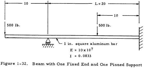
Find: The reaction moments and forces on the beam.
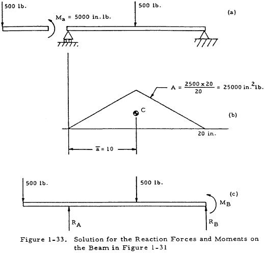
Solution: Figure 1-33(a) may be obtained by redrawing the beam as in Figure 1-31(b). The moment diagram may then be drawn for the right portion; and A, a, and MA may be determined as in Figure 1-33(b).
From Equation (1-38),
Now that MB is known, RA and RB may be found by applying the equations of statics to Figure 1-33(c). Doing this gives RA = 781 lb and RB = 219 lb.
Need a Beam Calculator?
Try this beam calculator.
- Calculates stresses and deflections in straight beams
- Builds shear and moment diagrams
- Can specify any configuration of constraints, concentrated forces, and distributed forces
1.3.4.3 Reaction Forces and Moments on Beams with Both Ends Fixed
Figure 1-34(a) shows a uniform beam with both ends fixed. The following procedure may be used to determine the support reactions on such a beam if its stresses are in the elastic range.
- Consider the beam to be simply supported as in Figure 1-34(b).
- Find the moment diagram for this simply supported beam as in Figure 1-34(c). A is the area of the moment diagram and C is the centroid of this area.
-
Find MA and MB by the equations
$$ M_A = { 2 A \over L^2 } ~( 2 \bar{b} - \bar{a} ) $$(1-39)$$ M_B = { 2 A \over L^2 } ~( 2 \bar{a} - \bar{b} ) $$The evaluation of the terms in these equations may be facilitated by the use of Table 1-10.(1-40)
- Evaluate RA and RB by applying the equations of statics to Figure 1-34(d).
Once the end reactions have been determined, the moment and shear diagrams may be constructed for the beam.
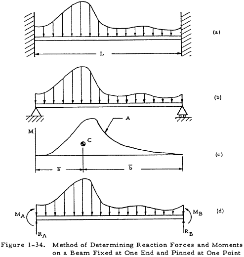
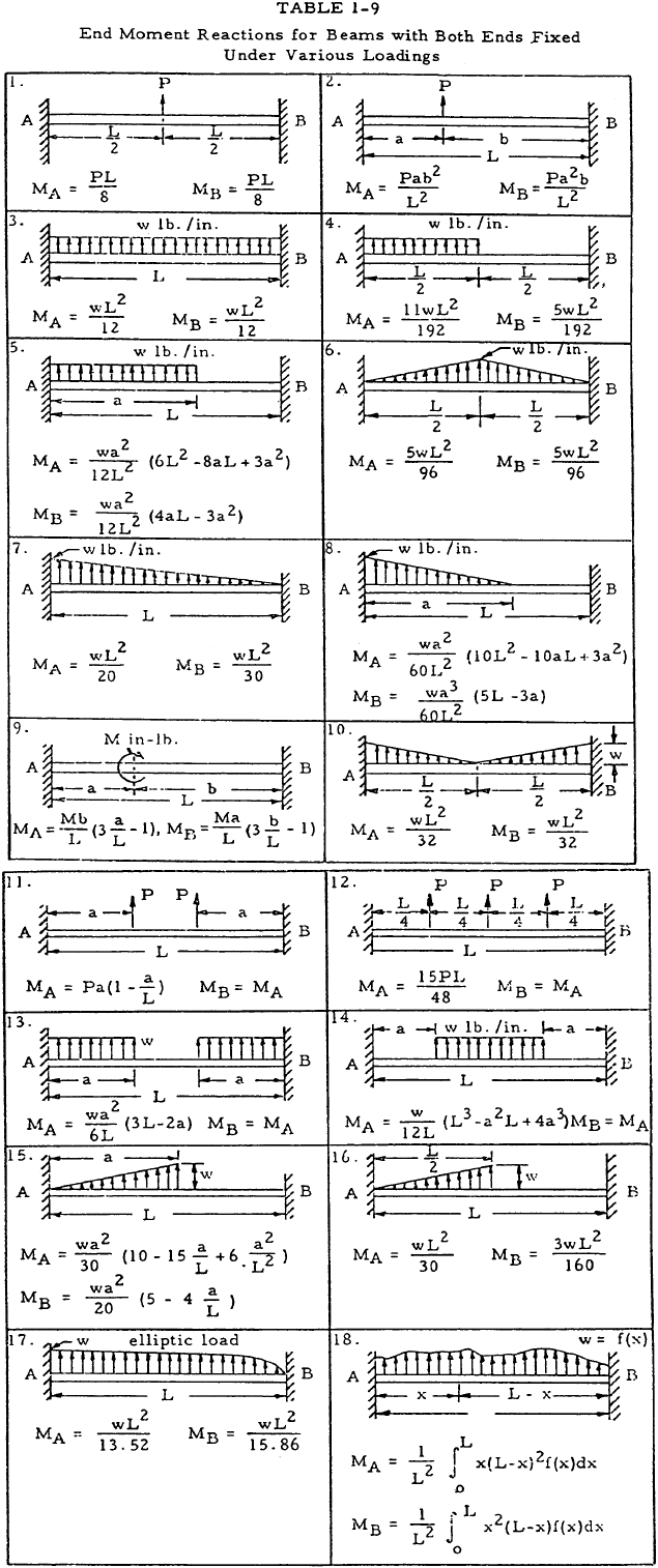
The above procedure may be avoided by using Table 1-9 which gives equations for the reaction moments for beams fixed at both ends under various loadings. The sign convention for this table are as shown in Figure 1-34(d).
Need a Beam Calculator?
Try this beam calculator.
- Calculates stresses and deflections in straight beams
- Builds shear and moment diagrams
- Can specify any configuration of constraints, concentrated forces, and distributed forces
1.3.4.4 Reaction Forces and Moments on Continuous Beams
A continuous beam is one with three or more supports. Such a beam is statically indeterminate and deflection equations must be applied to find the support reactions. The three-moment equation is such an equation.
1.3.4.5 Application of the Three Moment Equation to Solving for the Reactions on Continuous Beams
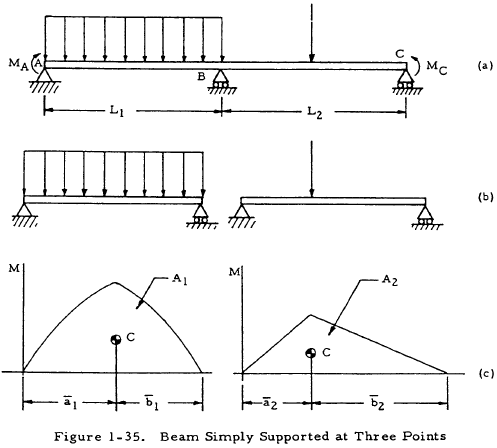
Figure 1-35(a) shows a uniform beam that is simply supported at three colinear points, A, B, and C. In order to obtain the reactions, the beam is broken into two simply supported sections with no end moments, as shown in Figure 1-35(b). The moment diagrams are then found for these sections and the area A and centroid C of these diagrams are found as shown in Figure 1-35(c). The quantities found may now be substituted into the three moment equation:
If MA and MC are known, this equation may be solved for the moment at B, MB. Knowing this moment, the support reactions at A, B, and C may be found by applying the equations of statics.
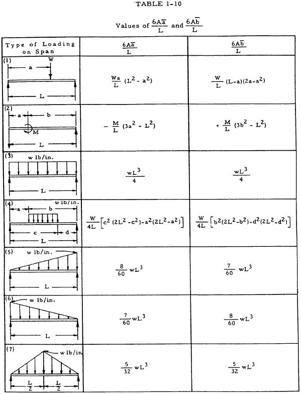
The terms to the right of Equation (1-41) may be found for various simple loadings by use of Table 1-10.
If a beam has a number of concentrated loads as shown in Figure 1-36, Equation (1-42) becomes
where P1 denotes any one of several concentrated loads which may act on the left span at a distance a1 from support A. Similarly, P2 denotes any load in the right span at a distance from support C.

If a beam is simply supported at more than thre.e points, the three-moment equation may be written for each intermediate support. The equations may then be solved simultaneously to obtain the moments at each support. This procedure is illustrated by the sample problem in Section 1.3.4.6.
Need a Beam Calculator?
Try this beam calculator.
- Calculates stresses and deflections in straight beams
- Builds shear and moment diagrams
- Can specify any configuration of constraints, concentrated forces, and distributed forces
1.3.4.6 Sample Problem - Reactions on Continuous Beams by the Three Moment Equation
Given: The continuous beam shown in Figure 1-37.
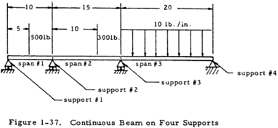
Find: The support reactions.
Solution: The three-moment equation may be written for spans 1 and 2. Since only concentrated loads are present, the special case given by Equation (1-42) may be used. Thus,
Inserting numerical values gives
Simplifying gives 5M2 + 2M3 = 3875.
The more general form of the three-moment equation given by Equation (1-41) may now be written for spans 2 and 3 with the aid of cases one and three of Table 1-10.
Simplifying gives 3M2 + 14M3 = -15,000.
The two equations in M2 and M3 that were just obtained may be solved simultaneously to find that M2 = -376 and M3 = -990.
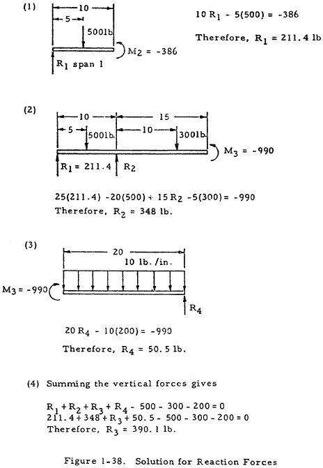
The equations of statics may now be applied as illustrated in Figure 1-38 to find the reaction forces.
The beam may now be drawn as in Figure 1-39.

