Beam Columns
This page provides the sections on beam columns from the "Stress Analysis Manual," Air Force Flight Dynamics Laboratory, October 1986.
Other related chapters from the Air Force "Stress Analysis Manual" can be seen to the right.
Nomenclature
| A | = | cross-sectional area |
| c | = | distance from neutral axis to extreme fiber |
| E | = | modulus of elasticity |
| I | = | moment of inertia |
| L | = | length |
| M | = | applied bending moment |
| Mt | = | bending moment due to transverse loads alone |
| P | = | axial load |
| U | = | \( L \sqrt{P \over EI} \) for beam column |
| W | = | concentrated transverse load |
| w | = | distributed transverse load |
| y | = | deflection of beam due to bending |
| θ | = | slope of beam |
1.4 Introduction to Beams Under Combined Axial and Transverse Loads - Beam Columns
A beam under combined axial and transverse loads cannot be analyzed by simply superposing the effects of the two types of loading. The method of solution must take into account the simultaneous effect of these loads, and may thus become quite complex. Axial tension tends to straighten the beam, thus counteracting the bending moments produced by the transverse load. On the other hand, since axial compression may greatly increase the bending moment and the slope and deflection of the beam, it is the more serious type of axial load.
Two methods of analysis may be used to determine the total fiber stress in members under combined axial and transverse loads. The first method, which is approximate in nature, assumes that the elastic curve of the deflected member is similar in form to the curve for a like member under the action of transverse loads alone. The moment due to deflection is estimated on this assumption and combined with the moment due to transverse loads. This approximate method is treated in Section 1.4.1. The other method, which is the exact one, makes use of the differential equation of the elastic curve and is treated in Section 1.4.2. The criteria for the use of these methods is given in these sections.
Need a Beam Calculator?
Try this beam calculator.
- Calculates stresses and deflections in straight beams
- Builds shear and moment diagrams
- Can specify any configuration of constraints, concentrated forces, and distributed forces
1.4.1 Approximate Method for Beams Under Combined Axial and Transverse Loads - Beam Columns
For any condition of combined axial and transverse loading, the maximum stress in the extreme fiber is given by
where P is the axial load and M is the maximum bending moment due to the combined effect of axial and transverse loads. (The plus sign is for fibers in which the direct stress and the bending stress are in the same direction, the minus sign for fibers in which they are in opposite directions.) If a column is comparatively stiff so that the bending moment due to the axial load is negligible, M may be set equal to the maximum moment due to transverse loads Mt alone. This may be done with an error of less than five percent if P < 0.125EI/L2 for cantilever beams, P < 0.5EI/L2 for beams with pinned ends, or P < 2EI/L2 for beams with fixed ends.
If 0.125EI/L2 < P < 0.8EI/L2 for cantilever beams and 0.5EI/L2 < P < 3EI/L2 for beams with fixed ends, the value of M for Equation (1-43) may be given by
for an error of less than five percent where K is given in Table 1-11 for various manners of loading and end support. The plus sign is used in the denominator if P is a tensile load and the minus sign is used if P is a compressive load. Equation (1-44) is appropriate only for beams in which the maximum bending moment and maximum deflection occur at the same section.
| Manner of Loading and Support | K |
|---|---|
| Cantilever, end load | 1/3 |
| Cantilever, uniform load | 1/4 |
| Pinned ends, center load | 1/12 |
| Pinned ends, uniform load | 5/48 |
| Equal and opposite end couples | 1/8 |
| Fixed ends, center load | 1/24 |
| Fixed ends, uniform load |
1/32 (for end moments) 1/16 (for center moments) |
Need a Beam Calculator?
Try this beam calculator.
- Calculates stresses and deflections in straight beams
- Builds shear and moment diagrams
- Can specify any configuration of constraints, concentrated forces, and distributed forces
1.4.2 Exact Method for Beams Under Combined Axial and Transverse Loads - Beam Columns
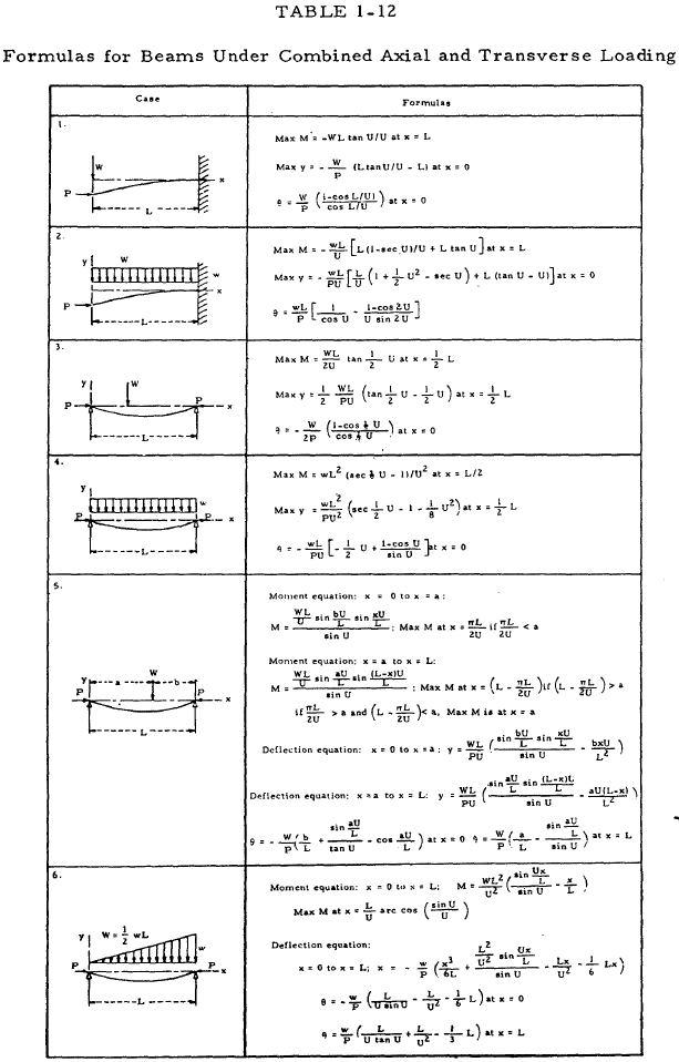
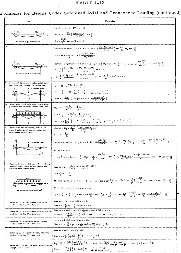
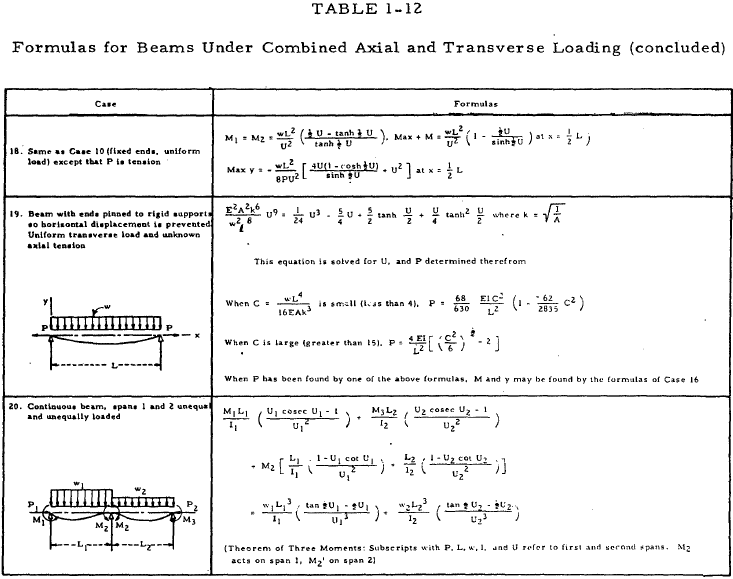
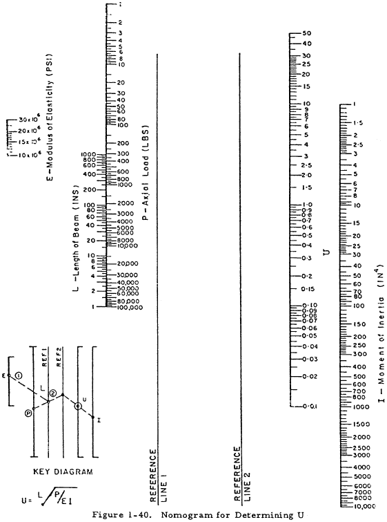
Table 1-12 gives exact formulas for the bending moment, M, deflection, y, and end slope, θ, in beams which are subjected to combined axial and transverse loading. Although these formulas should be used if P > 0.125EI/L2 for cantilever beams, P > 0.5EI/L2 for beams with pinned ends, or P > 2EI/L2 for beams with fixed ends, they may be used for beams with smaller axial loads. In these formulas, \(U = L\sqrt{P}/EI\). The quantity U may be found rapidly through the use of the nomogram in Figure 1-40. The formulas for beams under a compressive axial load may be modified to hold for a tensile axial load by making the following substitutions: -P for P; \(U\sqrt{-1}\) for U; \(\sqrt{-1} \sinh{U}\) for \(\sin{U}\); and \(\cosh{U}\) for \(\cos{U}\). This has been done for some of the more common loadings and the resulting formulas given in cases 13 to 18 of Table 1-12.
Need a Beam Calculator?
Try this beam calculator.
- Calculates stresses and deflections in straight beams
- Builds shear and moment diagrams
- Can specify any configuration of constraints, concentrated forces, and distributed forces
1.4.3 Sample Problem - Beams Under Combined Axial and Transverse Loads - Beam Columns
Given: The beam column shown in Figure 1-41.
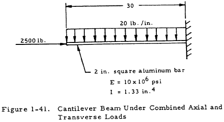
Find: The maximum bending moment, M, vertical deflection, y, and angular deflection, θ, of the bar.
Solution:
According to Section 1.4.2, the exact method must be used for cantilever beams if P < 0.125EI/L2 as is true in this case. From Figure 1-40,
From Table 1-12, Case 2,
$$ \begin{eqnarray} \theta &=& { w \over P } \left[ {L \over \cos{U}} - {L \over U} \left({ 1 - \cos{2U} \over \sin{2U} }\right) \right] \nonumber \\ &=& { 20 \over 2500 } \left[ {30 \over 0.915} - {30 \over 0.41} \left({ 1 - \cos{0.82} \over \sin{0.82} }\right) \right] \nonumber \\ &=& 0.0095 ~\text{rad} \nonumber \\ &=& 0.55^{\circ} \end{eqnarray} $$
