Shear Buckling of Flat Plates
This page provides the chapters on shear buckling of flat plates from the "Stress Analysis Manual," Air Force Flight Dynamics Laboratory, October 1986.
Other related chapters from the Air Force "Stress Analysis Manual" can be seen to the right.
- Analysis of Plates in Axial Compression
- Analysis of Plates in Bending
- Shear Buckling of Flat Plates
- Analysis of Curved Plates
- Analysis of Plates - Special Topics
Nomenclature
| a | = | plate length |
| b | = | plate width |
| E | = | modulus of elasticity |
| Es | = | secant modulus |
| Et | = | tangent modulus |
| f | = | ratio of cladding thickness to total plate thickness |
| F0.7, F0.85 | = | secant yield stress at 0.7E and 0.85E |
| Fcrs | = | critical shear stress |
| Fpl | = | stress at proportional limit |
| ks | = | shear buckling coefficient |
| n | = | shape parameter, number of half waves in buckled plate |
| ss | = | simply supported |
| t | = | thickness |
| W | = | total load, potential energy |
| β | = | ratio of cladding yield stress to core stress |
| ϵ | = | ratio of rotational rigidity of plate edge stiffeners |
| η | = | plasticity reduction factor |
| η | = | cladding reduction factor |
| λ | = | buckle half wavelength |
| ν | = | inelastic Poisson's ratio |
| νe | = | elastic Poisson's ratio |
6.5 Shear Buckling of Flat Plates
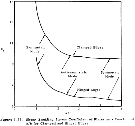
The critical shear-buckling stress of flat plates may be found from Equation (6-27).
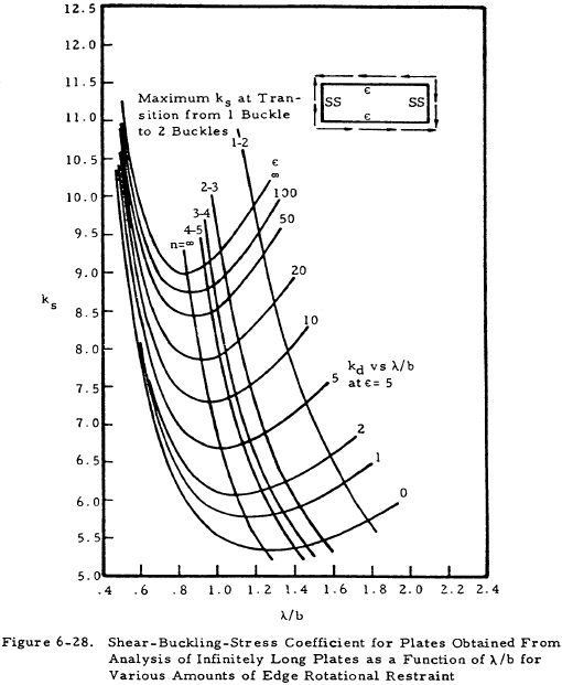
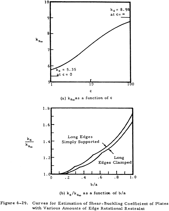
Figure 6-27 presents the shear coefficient ks, as a function of the size ratio a/b for clamped and hinged edges. For infinitely long plates, Figure 6-28 presents ks as a function of λ/b. Figure 6-29(a) presents ks∞ for long plates as a function of edge restraint, and Figure 6-29(b) gives ks∞ as a function of b/a, thus allowing the determination of ks.
The nondimensional chart in Figure 6-30 allows the calculation of inelastic shear buckling stresses if the secant yield stress, F0.7, and n the shape parameter is known (Table 6-11).
The plasticity-reduction factor η and the clodding factor η can be obtained from Equations (6-28), (6-29), and (6-30).
for Fcrs > Fpl
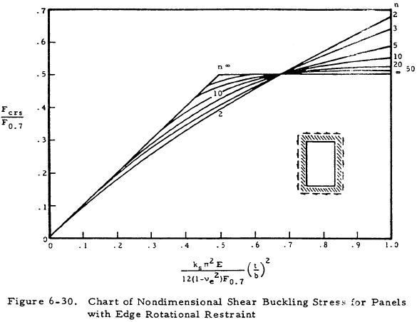
| n | Material |
|---|---|
| 3 | One-fourth hard to full hard 18-8 stainless steel One-fourth hard 18-8 stainless steel, cross grain |
| 5 | One-half hard and three-fourths hard 18-8 stainless steel, cross grain |
| 10 | Full hard 18-8 stainless steel, cross grain 2024-T and 7075-T aluminum-alloy sheet and extrusion 2024R-T aluminum-alloy sheet |
| 20 to 25 | 2024-T80, 2024-T81, and 2024-T86 aluminum alloy sheet 2024-T aluminum-alloy extrusion SAE 4130 steel heat-treated up to 100,000 psi ultimate stress |
| ∞ | 2014-T aluminum-alloy extrusions SAE 4130 steel heat-treated above 125,000 psi ultimate stress |
