


Thermal Shock
This page provides the chapters on thermal shock (thermal stress) from the "DOE Fundamentals Handbook: Material Science," DOE-HDBK-1017/1-93, U.S. Department of Energy, Jan 1993.
Other related chapters from the "DOE Fundamentals Handbook: Material Science" can be seen to the right.
Thermal Stress
Thermal stresses arise in materials when they are heated or cooled. Thermal stresses effect the operation of facilities, both because of the large components subject to stress and because they are effected by the way in which the plant is operated. This chapter describes the concerns associated with thermal stress.
Thermal Shock
Thermal shock (stress) can lead to excessive thermal gradients on materials, which lead to excessive stresses. These stresses can be comprised of tensile stress, which is stress arising from forces acting in opposite directions tending to pull a material apart, and compressive stress, which is stress arising from forces acting in opposite directions tending to push a material together. These stresses, cyclic in nature, can lead to fatigue failure of the materials.
Thermal shock is caused by nonuniform heating or cooling of a uniform material, or uniform heating of nonuniform materials. Suppose a body is heated and constrained so that it cannot expand. When the temperature of the material increases, the increased activity of the molecules causes them to press against the constraining boundaries, thus setting up thermal stresses.
If the material is not constrained, it expands, and one or more of its dimensions increases. The thermal expansion coefficient (α) relates the fractional change in length ΔL/L, called thermal strain, to the change in temperature per degree ΔT.
where:
| L = length (in.) |
| ΔL = change in length (in.) |
| α = linear thermal expansion coefficient (°F-1) |
| ΔT = change in temperature (°F) |
Table 1 lists the coefficients of linear thermal expansion for several commonly-encountered materials.
| Material | Coefficients of Linear Thermal Expansion (°F-1) |
|---|---|
| Carbon Steel | 5.8×10⁻⁶ |
| Stainless Steel | 9.6×10⁻⁶ |
| Aluminum | 13.3×10⁻⁶ |
| Copper | 9.3×10⁻⁶ |
| Lead | 16.3×10⁻⁶ |
In the simple case where two ends of a material are strictly constrained, the thermal stress can be calculated using Hooke's Law by equating values of ΔL/L from Equations (3-1), (3-2), and (3-3).
or
where:
| F/A = thermal stress (psi) |
| E = modulus of elasticity (psi) |
| α = linear thermal expansion coefficient (°F-1) |
| ΔT = change in temperature (°F) |
Example: Given a carbon steel bar constrained at both ends, what is the thermal stress when heated from 60°F to 540°F?
Solution:
| α = 5.8×10⁻⁶/°F (from Table 1) |
| E = 3.0×10⁷ lb/in.2 (from Table 1, Module 2) |
| ΔT = 540°F - 60°F = 480°F |
| Stress = F/A = EαΔT = (3.0×10⁷ lb/in.2) × (5.8×10-6/°F) × 480°F |
| Thermal stress = 8.4×10⁴ lb/in.2 (which is higher than the yield point) |
Thermal stresses are a major concern in reactor systems due to the magnitude of the stresses involved. With rapid heating (or cooling) of a thick-walled vessel such as the reactor pressure vessel, one part of the wall may try to expand (or contract) while the adjacent section, which has not yet been exposed to the temperature change, tries to restrain it. Thus, both sections are under stress. Figure 1 illustrates what takes place.
A vessel is considered to be thick-walled or thin-walled based on comparing the thickness of the vessel wall to the radius of the vessel. If the thickness of the vessel wall is less than about 1 percent of the vessel's radius, it is usually considered a thin-walled vessel. If the thickness of the vessel wall is more than 5 percent to 10 percent of the vessel's radius, it is considered a thick-walled vessel. Whether a vessel with wall thickness between 1 percent and 5 percent of radius is considered thin-walled or thick-walled depends on the exact design, construction, and application of the vessel.
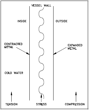
When cold water enters the vessel, the cold water causes the metal on the inside wall (left side of Figure 1) to cool before the metal on the outside. When the metal on the inside wall cools, it contracts, while the hot metal on the outside wall is still expanded. This sets up a thermal stress, placing the cold side in tensile stress and the hot side in compressive stress, which can cause cracks in the cold side of the wall. These stresses are illustrated in Figure 2 and Figure 3 in the next chapter.
The heatup and cooldown of the reactor vessel and the addition of makeup water to the reactor coolant system can cause significant temperature changes and thereby induce sizable thermal stresses. Slow controlled heating and cooling of the reactor system and controlled makeup water addition rates are necessary to minimize cyclic thermal stress, thus decreasing the potential for fatigue failure of reactor system components.
Operating procedures are designed to reduce both the magnitude and the frequency of these stresses. Operational limitations include heatup and cooldown rate limits for components, temperature limits for placing systems in operation, and specific temperatures for specific pressures for system operations. These limitations permit material structures to change temperature at a more even rate, minimizing thermal stresses.
We have a number of structural calculators to choose from. Here are just a few:

Pressurized Thermal Shock
Personnel need to be aware how pressure combined with thermal stress can cause failure of plant materials. This chapter addresses thermal shock (stress) with pressure excursions.
Definition
One safety issue that is a long-term problem brought on by the aging of nuclear facilities is pressurized thermal shock (PTS). PTS is the shock experienced by a thick-walled vessel due to the combined stresses from a rapid temperature and/or pressure change. Nonuniform temperature distribution and subsequent differential expansion and contraction are the causes of the stresses involved. As the facilities get older in terms of full power operating years, the neutron radiation causes a change in the ductility of the vessel material, making it more susceptible to embrittlement. Thus, if an older reactor vessel is cooled rapidly at high pressure, the potential for failure by cracking increases greatly.
Evaluating Effects of PTS
Changes from one steady-state temperature or pressure to another are of interest for evaluating the effects of PTS on the reactor vessel integrity. This is especially true with the changes involved in a rapid cooldown of the reactor system, which causes thermal shock to the reactor vessel. These changes are called transients. Pressure in the reactor system raises the severity of the thermal shock due to the addition of stress from pressure. Transients, which combine high system pressure and a severe thermal shock, are potentially more dangerous due to the added effect of the tensile stresses on the inside of the reactor vessel wall. In addition, the material toughness of the reactor vessel is reduced as the temperature rapidly decreases.
Stresses arising from coolant system pressure exerted against the inside vessel wall (where neutron fluence is greatest) are always tensile in nature. Stresses arising from temperature gradients across the vessel wall can either be tensile or compressive. The type of stress is a function of the wall thickness and reverses from heatup to cooldown. During system heatup, the vessel outer wall temperature lags the inner wall temperature. The stresses produced by this temperature gradient and by system pressure will produce the profile shown in Figure 2.
During heatup, it can be seen that while the pressure stresses are always tensile, at the 1/4 thickness (1/4 T), the temperature stresses are compressive. Thus, the stresses at the 1/4 T location tend to cancel during system heatup. At the 3/4 T location, however, the stresses from both temperature and pressure are tensile and thus, reinforce each other during system heatup. For this reason the 3/4 T location is limiting during system heatup.

During system cooldown, the stress profile of Figure 3 is obtained. During cooldown, the outer wall lags the temperature drop of the inner wall and is at a higher temperature. It can be seen that during cooldown, the stresses at the 3/4 T location are tensile due to system pressure and compressive due to the temperature gradient. Thus during cooldown, the stresses at the 3/4 T location tend to cancel. At the 1/4 T location, however, the pressure and temperature stresses are both tensile and reinforce each other. Thus, the 1/4 T location is limiting during system cooldown.
Plant temperature transients that have the greatest potential for causing thermal shock include excessive plant heatup and cooldown, plant scrams, plant pressure excursions outside of normal pressure bands, and loss of coolant accidents (LOCAs). In pressurized water reactors (PWRs), the two transients that can cause the most severe thermal shock to the reactor pressure vessel are the LOCA with subsequent injection of emergency core cooling system (ECCS) water and a severe increase in the primary-tosecondary heat transfer.

Locations of Primary Concern
Locations in the reactor system, in addition to the reactor pressure vessel, that are primary concerns for thermal shock include the pressurizer spray line and the purification system.