Application of Newton's Laws
This page provides the chapter on the application of Newton's laws from the "DOE Fundamentals Handbook: Classical Physics," DOE-HDBK-1010-92, U.S. Department of Energy, June 1992.
Other related chapters from the "DOE Fundamentals Handbook: Classical Physics" can be seen to the right.
- Unit Systems
- Vectors
- Force and Motion
- Application of Newton's Laws
- Energy, Work, and Power
Force and Weight
Force can be thought of simply as a push or pull, but is more clearly defined as any action on a body that tends to change the velocity of the body. Weight is a force exerted on an object due to the object's position in a gravitational field.
Introduction
In the study of forces, the student must make valid assumptions called for in the formulation of real problems. The ability to understand and make use of the correct assumptions in the formulation and solution of engineering problems is certainly one of the most important abilities of a successful operator. One of the objectives of this manual is to provide an opportunity to develop this ability through the study of the fundamentals and the analysis of practical problems.
An effective method of attack on all engineering problems is essential. The development of good habits in formulating problems and in representing their solutions will prove to be a valuable asset. Each solution should proceed with a logical sequence of steps from hypothesis to conclusion, and its representation should include a clear statement of the following parts, each clearly defined: a) given data, b) results desired, c) necessary diagrams, d) calculations, and e) answers and conclusions. Many problems become clear and straightforward once they are begun with a logical and disciplined method of attack.
The subject of classical physics is based on surprisingly few fundamental concepts and involves mainly the application of these basic relations to a variety of situations. Newton's laws of motion are some of the fundamental concepts used in the study of force and weight.
Force
Force is defined as a vector quantity that tends to produce an acceleration of a body in the direction of its application. Changing the body's velocity causes the body to accelerate. Therefore, force can be mathematically defined as given by Newton's second law of motion (Equation 4-1).
where:
| F | = | force on object (Newton or lbf) |
| m | = | mass of object (kg or lbm) |
| a | = | acceleration of object (m/sec2 or ft/sec2) |
Force is characterized by its point of application, its magnitude, and its direction. A force that is actually distributed over a small area of the body upon which it acts may be considered a concentrated force if the dimensions of the area involved are small compared with other pertinent dimensions.
Two or more forces may act upon an object without affecting its state of motion. For example, a book resting upon a table has a downward force acting on it caused by gravity and an upward force exerted on it from the table top. These two forces cancel and the net force of the book is zero. This fact can be verified by observing that no change in the state of motion has occurred.
Weight
Weight is a special application of the concept of force. It is defined as the force exerted on an object by the gravitational field of the earth, or more specifically the pull of the earth on the body.
where:
| W | = | weight (lbf) |
| m | = | mass (lbm) of the object |
| g | = | the local acceleration of gravity (32.17 ft/sec2) |
| gc | = | a conversion constant employed to facilitate the use of Newton's second law of motion with the English system of units and is equal to 32.17 ft-lbm/lbf-sec2 |
Note that gc has the same numerical value as the acceleration of gravity at sea level.
The mass of a body is the same wherever the body is, whether on the moon or on the earth. The weight of a body, however, depends upon the local acceleration of gravity. Thus, the weight of an object is less on the moon than on the earth because the local acceleration of gravity is less on the moon than on the earth.
Example:
Calculate the weight of a person with a mass of 185 lbm.
$$ \begin{eqnarray} W &=& {mg \over g_c} \nonumber \\ &=& { (185 ~\text{lbm}) \left(32.17 ~{\text{ft} \over \text{sec}^2}\right) \over 32.17 ~{ \text{ft-lbm} \over \text{lbf-sec}^2 } } \nonumber \\ &=& 185 ~\text{lbf} \end{eqnarray} $$Example:
Calculate the weight of a person with a mass of 185 lbm on the moon. Gravity on the moon is 5.36 ft/sec2.
$$ \begin{eqnarray} W &=& {mg \over g_c} \nonumber \\ &=& { (185 ~\text{lbm}) \left(5.36 ~{\text{ft} \over \text{sec}^2}\right) \over 32.17 ~{ \text{ft-lbm} \over \text{lbf-sec}^2 } } \nonumber \\ &=& 28.19 ~\text{lbf} \end{eqnarray} $$With the idea of mass and weight understood, especially their differences, the concept of gravitational force is more easily explained. Any object that is dropped will accelerate as it falls, even though it is not in physical contact with any other body. To explain this, the idea of gravitational force was developed, resulting in the concept that one body, such as the earth, exerts a force on another body, even though they are far apart. The gravitational attraction of two objects depends upon the mass of each and the distance between them. This concept is known as Newton's law of gravitation, which was introduced in an earlier chapter.
We have a number of structural calculators to choose from. Here are just a few:
Free-Body Diagrams
In studying the effect of forces on a body it is necessary to isolate the body and determine all forces acting upon it. This method of using a free-body diagram is essential in understanding basic and complex force problems.
In solving a problem involving forces it is essential that Newton's laws are carefully fixed in mind and that these principles are applied literally and exactly. In applying these principles it is essential that the body be isolated from all other bodies so that a complete and accurate account of all forces which act on this body may be considered. The diagram of such an isolated body with the representation of all external forces acting on it is called a Free-Body Diagram. It has long been established that the free-body-diagram method is the key to the understanding of engineering problems. This is because the isolation of a body is the tool that clearly separates cause and effect and focuses our attention to the literal application of a principle.
Example:
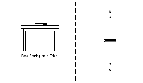
Consider the book resting on the table in Figure 1. Although the book is stationary, two forces are acting on the book to keep it stationary. One is the weight (W) of the book exerting a force down on the table. The other is the force exerted up by the table to hold the book in place. This force is known as the normal force (N) and is equal to the weight of the book. A normal force is defined as any perpendicular force with which any two surfaces are pressed against each other. The free-body diagram for this situation, illustrated on the right side in Figure 1, isolates the book and presents the forces acting on the object.
Constructing a Free-Body Diagram
In constructing a free-body diagram the following steps are usually followed.
| Step 1. | Determine which body or combination of bodies is to be isolated. The body chosen will usually involve one or more of the desired unknown quantities. |
| Step 2. | Next, isolate the body or combination of bodies chosen with a diagram that represents its complete external boundaries. |
| Step 3. | Represent all forces that act on the isolated body as applied by the removed contacting and attracting bodies in their proper positions in the diagram of the isolated body. Do not show the forces that the object exerts on anything else, since these forces do not affect the object itself. |
| Step 4. | Indicate the choice of coordinate axes directly on the diagram. Pertinent dimensions may also be represented for convenience. Note, however, that the free-body diagram serves the purpose of focusing accurate attention on the action of the external forces; therefore, the diagram should not be cluttered with excessive information. Force arrows should be clearly distinguished from other arrows to avoid confusion. For this purpose colored pencils may be used. |
When these steps are completed a correct free-body diagram will result, and the student can apply the appropriate equations to the diagram to find the proper solution.
Example:
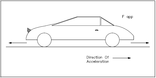
The car in Figure 2 is being towed by a force of some magnitude. Construct a free-body diagram showing all the forces acting on the car.
Solution:
Following the steps to construct a free-body diagram (shown in Figure 3), the object (the car) is chosen and isolated. All the forces acting on the car are represented with proper coordinate axes. Those forces are:
| Fapp | - | The force applied to tow the car |
| FK | - | The frictional force that opposes the applied force due to the weight of the car and the nature of the surfaces (the car's tires and the road) |
| W | - | The weight of the car |
| N | - | The normal force exerted by the road on the car |
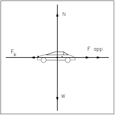
The frictional force (FK) is a force that opposes the direction of motion. This force is explained in more detail in the chapter on types of forces.
To solve this practical problem, the student would assign values for each force as determined by data given in the problem. After assigning a sign convention (e.g., + for forces upward and to the right, − for forces downward and to the left), the student would sum all forces to find the net force acting on the body. Using this net force information and appropriate equations, the student could solve for the requested unknowns. A variation would be to have the student find an unknown force acting on the body given sufficient information about the other forces acting on the body. The student will learn to solve specific examples using free-body diagrams in a later chapter.
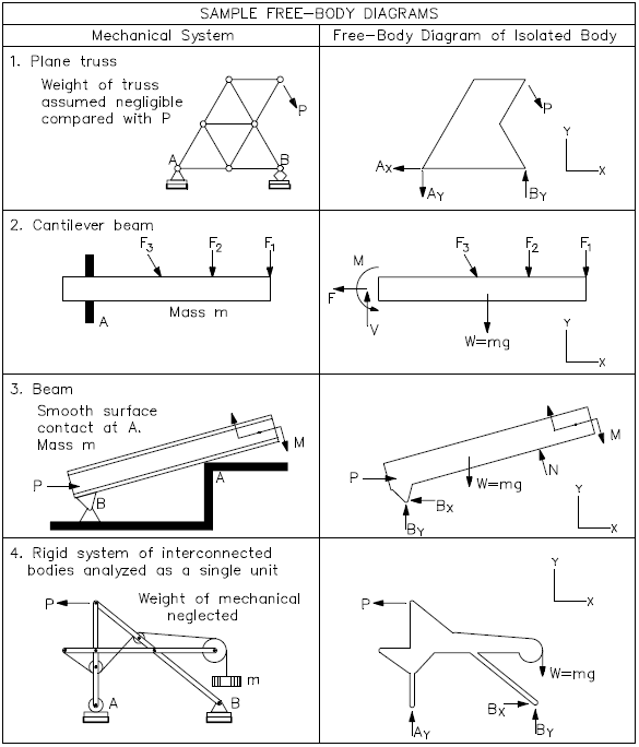
Some advanced free-body diagrams for various types of systems are shown in Figure 4.
We have a number of structural calculators to choose from. Here are just a few:
Force Equilibrium
Knowledge of the forces required to maintain an object in equilibrium is essential in understanding the nature of bodies at rest and in motion.
Net Force
When forces act on an object, the result may be a change in the object's state of motion. If certain conditions are satisfied, however, the forces may combine to maintain a state of equilibrium or balance.
To determine if a body is in equilibrium, the overall effect of all the forces acting on it must be assessed. All the forces that act on an object result in essentially one force that influences the object's motion. The force which results from all the forces acting on a body is defined as the net force. It is important to remember that forces are vector quantities. When analyzing various forces you must account for both the magnitude (displacement) of the force as well as the direction in which the force is applied. As described in the previous chapter, this is best done using a free-body diagram.
To understand this more clearly, consider the book resting on the table in section A of Figure 5.
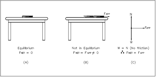
The book remains stationary resting on the table because the table exerts a normal force upward equal to the weight of the book. Therefore, the net force on the book is zero. If a force is applied to the book (section B of Figure 5), and the effect of friction is neglected, the net force will be equal to the applied force, and the book will move in the direction of the applied force. The free-body diagram in section C of Figure 5 shows that the weight (W) of the book is canceled by the normal force (N) of the table since they are equal in magnitude but opposite in direction. The resultant (net) force is therefore equal to the applied force (FAPP).
Equilibrium
Since an object in equilibrium is considered to be in a state of balance, it can be surmised that the net force on the object is equal to zero. That is, if the vector sum of all the forces acting on an object is equal to zero, then the object is in equilibrium.
Newton's first law of motion describes equilibrium and the effect of force on a body that is in equilibrium. That law states "An object remains at rest (if originally at rest) or moves in a straight line with a constant velocity if the net force on it is zero." Newton's first law of motion is also called the law of inertia. Inertia is the tendency of a body to resist a change in its state of motion.
The first condition of equilibrium, a consequence of Newton's first law, may be written in vector form, "A body will be in translational equilibrium if and only if the vector sum of forces exerted on a body by the environment equals zero."
For example, if three forces act on a body it is necessary for the following to be true for the body to be in equilibrium.
This equation may also be written as follows.
This sum includes all forces exerted on the body by its environment. The vanishing of this vector sum is a necessary condition, called the first condition of equilibrium, that must be satisfied in order to ensure translational equilibrium. In three dimensions (x,y,z), the component equations of the first condition of equilibrium are:
| Σ FX = 0 | Σ FY = 0 | Σ FZ = 0 |
This condition applies to objects in motion with constant velocity and to bodies at rest or in static equilibrium (referred to as STATICS).
Applying the knowledge that an object in equilibrium has a net force equal to zero, the following example can be solved:
Example:
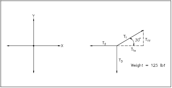
The object in Figure 6 has a weight of 125 lbf. The object is suspended by cables as shown. Calculate the tension (T1) in the cable at 30° with the horizontal.
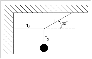
The tension in a cable is the force transmitted by the cable. The tension at any point in the cable can be measured by cutting a suitable length from it and inserting a spring scale.
Solution:
Since the object and its supporting cables are motionless (i.e., in equilibrium), we know that the net force acting on the intersection of the cables is zero. The fact that the net force is zero tells us that the sum of the x-components of T1, T2, and T3 is zero, and the sum of the y-components of T1, T2, and T3 is zero.
Σ Fx = T1.x + T2.x + T3.x = 0
Σ Fy = T1.y + T2.y + T3.y = 0
The tension T3 is equal to the weight of the object, 125 lbf. The x and y components of the tensions can be found using trigonometry (e.g., sine function). Substituting known values into the second equation above yields the following.
A simpler method to solve this problem involves assigning a sign convention to the free-body diagram and examining the direction of the forces.
By choosing (+) as the upward direction and (−) as the downward direction, the student can determine by examination that 1) the upward component of T1 is +T1sin30°, 2) the tension T3 is −125 lbf, and 3) T2 has no y- component. Therefore, using the same equation as before, we obtain the following.
$$ \begin{eqnarray} \Sigma F_y = (T_1 \sin 30^{\circ}) - 125 ~\text{lbf} &=& 0 \nonumber \\ 0.5 ~T_1 &=& 125 ~\text{lbf} \nonumber \\ T_1 &=& 250 ~\text{lbf} \end{eqnarray} $$If the sum of all forces acting upon a body is equal to zero, that body is said to be in force equilibrium. If the sum of all the forces is not equal to zero, any force or system of forces capable of balancing the system is defined as an equilibrant.
Example:
A 2000 lbm car is accelerating (on a frictionless surface) at a rate of 2 ft/sec2. What force must be applied to the car to act as an equilibrant for this system?
Solution:
a. Draw a free-body diagram.
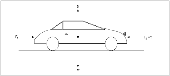
b. A force, F2, MUST be applied in the opposite direction to F1 such that the sum of all forces acting on the car is zero.
c. Since the car remains on the surface, forces N and W are in equal and opposite directions. Force F2 must be applied in an equal and opposite direction to F1 in order for the forces to be in equilibrium.
$$ \begin{eqnarray} F_2 = F_1 = {ma \over g_c} &=& (2000 ~\text{lbm} \times 2 ~\text{ft/sec}^2) \div 32.17 ~{\text{ft-lbm} \over \text{lbf-sec}^2} \nonumber \\ &=& 124 ~\text{lbf} \end{eqnarray} $$We have a number of structural calculators to choose from. Here are just a few:
Types of Force
When determining how an object reacts to a force or forces, it is important to understand the different types of forces that may act on the object.
The previous section discussed the equilibrium of forces as they act on bodies. Recalling that a force is defined as a vector quantity that tends to produce an acceleration of a body in the direction of its application, it is apparent that the student must be acquainted with the various types of forces that exist in order to construct a correct free-body diagram and apply the appropriate equation. A force is applied either by direct mechanical contact or by remote action.
Tensile and Compressive Forces
In discussing the types of forces, a simple rule is used to determine if the force is a tensile or a compressive force. If an applied force on a member tends to pull the member apart, it is said to be in tension. If a force tends to compress the member, it is in compression. It should also be mentioned that ropes, cables, etc., that are attached to bodies can only support tensile loads, and therefore such objects are in tension when placed on the free-body diagram. In addition, when a fluid is involved, it should be understood that fluid forces are almost always compressive forces.
Friction
Another type of force often used in classical physics is the force resulting from two surfaces in contact, where one of the surfaces is attempting to move parallel to or over the other surface. Such forces are referred to as friction forces. There are two types of friction forces: those due to dry friction, sometimes called Coulomb friction, and those resulting from fluid friction.
Fluid friction develops between layers of fluid moving at different velocities. This type of frictional force is used in considering problems involving the flow of fluids through pipes. Such problems are covered in the Fundamentals Manual on fluid flow. In this section, problems involving rigid bodies which are in contact along dry surfaces are considered.
The laws of dry friction are best understood by the following experiment. A block of weight W is placed on a horizontal plane surface (see Figure 9). The forces acting on the block are its weight W and the normal force N of the surface. Since the weight has no horizontal component, the normal force of the surface also has no horizontal component; the reaction is therefore normal to the surface and is represented by N in part (a) of the figure. Suppose now, that a horizontal force P is applied to the block (see part (b)). If P is small, the block will not move. Some other horizontal force must therefore exist which balances P. This other force is the static-friction force F, which is actually the resultant of a great number of forces acting over the entire surface of contact between the block and the plane. The nature of these forces is not known exactly, but it is generally assumed that these forces are due to the irregularities of the surfaces in contact and also to molecular action.
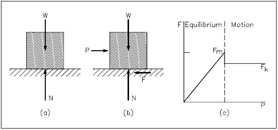
If the force P is increased, the friction force F also increases, continuing to oppose P, until its magnitude reaches a certain maximum value FM (see part (c) of Figure 9). If P is further increased, the friction force cannot balance it any more, and the block starts sliding. As soon as the block has been set in motion, the magnitude of F drops from FM to a lower value FK. This is because there is less interpenetration between the irregularities of the surfaces in contact when these surfaces move with respect to one another. From then on, the block keeps sliding with increasing velocity (i.e., it accelerates) while the friction force, denoted by FK and called the kinetic-friction force, remains approximately constant.
Experimental evidence shows that the maximum value FM of the static-friction force is proportional to the normal component N of the reaction of the surface, as shown in Equation 4-5.
The term μS is a constant called the coefficient of static friction. Similarly, the magnitude FK of the kinetic-friction force may be expressed in the following form.
The term μK is a constant called the coefficient of kinetic friction. The coefficients of friction, μS and μK, do not depend upon the area of the surfaces in contact. Both coefficients, however, depend strongly on the nature of the surfaces in contact. Since they also depend upon the exact condition of the surfaces, their value is seldom known with an accuracy greater than 5 percent. It should be noted that frictional forces are always opposite in direction to the motion (or impending motion) of the object.
Centripetal Force
An object moving at constant speed in a circle is not in equilibrium. Although the magnitude of the linear velocity is not changing, the direction of velocity is continually changing. Since a change in direction requires acceleration, an object moving in a circular path has a constant acceleration towards the center of the circular path.
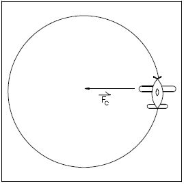
Recalling Newton's second law of motion, F = ma, a force is required to cause acceleration. Therefore, to have constant acceleration towards the center of the circular path, there must be a net force acting towards the center. This force is known as centripetal force. Without this force, an object will move in a straight line. Figure 10 illustrates the centripetal force.
Centrifugal Force
Another force, which appears to be opposite the direction of motion, is the centrifugal force acting on an object that follows a curved path. This force appears to be a force directed away from the center of the circular path. This is actually a fictitious force, but is an apparent force that is used to describe the forces present due to an object's rotation.
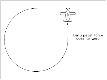
To better understand centripetal and centrifugal forces, consider that a string is attached to the plane in Figure 10. As the plane rotates about the center, the string places a centripetal force on the plane. This causes the plane's velocity to change in direction, thus causing it to travel in a circle.
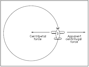
The apparent outward force, centrifugal force, seems to pull the plane away from the center shown in Figure 11. This is the same apparent outward force one feels when riding in a car when the car travels in a circle. It can be proven that centrifugal force is not an actual force by cutting the string. In doing so, the plane will fly off in a straight line that is tangent to the circle at the velocity it had the moment the string was cut. If there were an actual centrifugal force present, the plane would not fly away in a line tangent to the circle, but would fly directly away from the circle (see Figure 12).
PDH Classroom offers a continuing education course based on this application of Newton's laws reference page. This course can be used to fulfill PDH credit requirements for maintaining your PE license.
Now that you've read this reference page, earn credit for it!
