Analysis of Plates - Special Topics
This page provides the chapters on plates under combined loadings, buckling of oblique plates, and buckling of sandwich panels from the "Stress Analysis Manual," Air Force Flight Dynamics Laboratory, October 1986.
Other related chapters from the Air Force "Stress Analysis Manual" can be seen to the right.
- Analysis of Plates in Axial Compression
- Analysis of Plates in Bending
- Shear Buckling of Flat Plates
- Analysis of Curved Plates
- Analysis of Plates - Special Topics
Nomenclature
| a | = | plate length |
| b | = | plate width |
| c | = | core thickness, signifies clamped edge |
| C | = | compressive buckling coefficient for curved plates |
| E | = | modulus of elasticity |
| F | = | stress |
| Fcr | = | critical normal stress |
| Fcrs | = | critical shear stress |
| Fcy | = | compressive yield stress |
| kc | = | compressive buckling coefficient |
| K | = | sandwich panel form factor |
| R | = | stress ratio |
| t | = | thickness |
| Zb | = | length range parameter b2(1 - νe2)1/2/ rt |
| η | = | plasticity reduction factor |
| η | = | cladding reduction factor |
| ν | = | inelastic Poisson's ratio |
6.8 Plates Under Combined Loadings
In general, the loadings on aircraft elements are a combination of two or more simple loadings. Design of such elements must consider the interaction of such loadings and a possible reduction of the allowable values of the simple stresses when combined loads are present. The method using stress ratios, R, has been used extensively in aircraft structural design. The ratio R is the ratio of the stress in the panel at buckling under combined loading to the buckling stress under the simple loading. In general, failure occurs when Equation (6-36) is satisfied. The exponents x and y must be determined experimentally and depend upon the structural element and the loading condition.
6.8.1 Flat Plates Under Combined Loadings
Table 6-12 gives the combined loading condition for flat plates. Figures 6-36 and 6-37 give interaction curves for several loading and support conditions. It is noted that the curves present conditions of triple combinations.
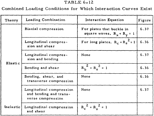
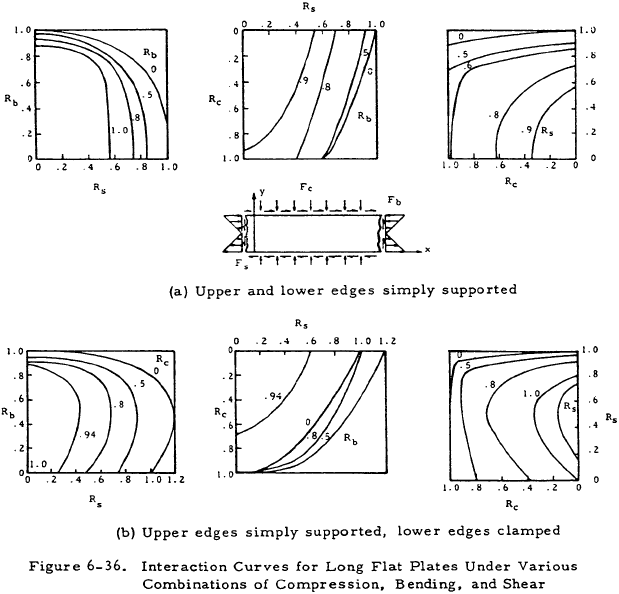
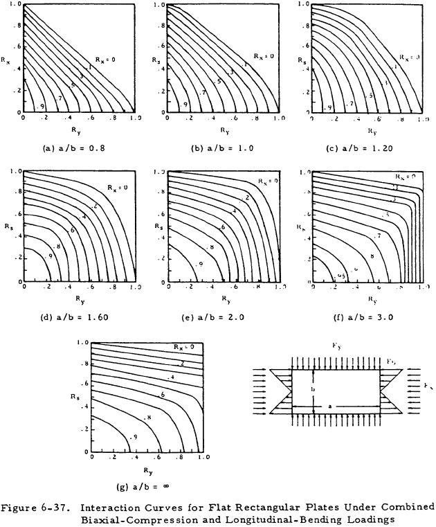
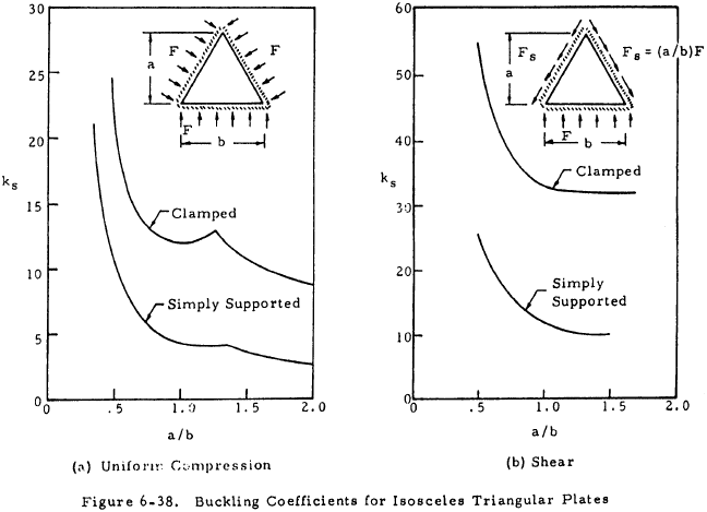
Figure 6-38 presents buckling coefficients for right angle isosceles triangular plates loaded under shear and compression. Equation (6-37) is the interaction equation for shear and normal stress on this type of plate.
The + and − subscripts refer to either tension or compression along the altitude upon the hypotenuse of the triangle caused by pure shear loading. Table 6-13 contains values of kc, ks+ and ks− for various edge supports.
| Edge Supports (Note a) | kc | ks+ | ks− |
|---|---|---|---|
| All edges simply supported | 10.0 | 62.0 | 23.2 |
| Sides simply supported, hypotenuse clamped |
15.6 | 70.8 | 34.0 |
| Sides clamped, hypottenuse simply supported |
18.8 | 80.0 | 44.0 |
| Note a: Hypotenuse = b in Figure 6.38 | |||
6.8.2 Curved Plates Under Combined Loadings
For curved plates under combined axial loading and shear with 10 < Zb < 100 and 1 < a/b < 3, the interaction relation of Equation (6-39) may be used.
This may be used for either compression or tension with tension being denoted by a negative sign.
We have a number of structural calculators to choose from. Here are just a few:
6.9 Buckling of Oblique Plates
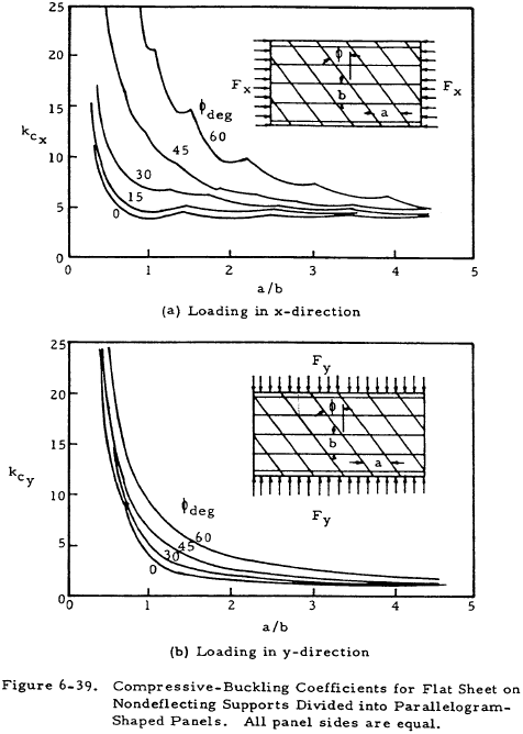
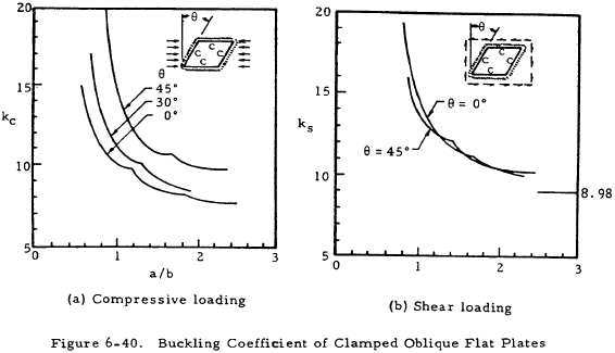
In many instances, the use of rectangular panels is not possible. Figures 6-39 and 6-40 give buckling coefficients for panels which are oriented oblique to the loading. Figure 6-39 covers flat plates divided into oblique parallelogram panels by nondeflecting supports. Figure 6-40 covers single oblique panels.
6.10 Sample Problem - Plate Analysis
Find: The buckling stress of a flat plate under uniform longitudinal compression, simply supported on all four sides.
Given: a = 12 in, b = 4 in, t = 0.100 in.
Material: Bare 2024-T3 Sheet
| Material Properties: | E = 10.7 x 10⁶ psi |
| ν = 0.33 | |
| Fcy = 34,000 psi |
Solution:
$$ F_{cr} = \overline{\eta} ~\eta ~{ k_c ~\pi^2 E \over 12 (1 - \nu^2) } \left({t \over b}\right)^2 $$From Figure 6-1 for a/b = 3, kc= 4.00.
| η = 1.0 for no cladding |
| η = 1.0 for elastic buckling |
| Fcr = 24,600 psi |
As this is below the compression yield strength, no allowance for elasticity need be made.
We have a number of structural calculators to choose from. Here are just a few:
6.11 Buckling of Sandwich Panels
The use of sandwich construction for skin panels of aircraft has become commonplace. Panel construction consists of primary and secondary skins separated by a core which is usually some form of honeycomb or expanded foam material. The critical buckling stress of such a composite can be calculated from Equation (6-40).
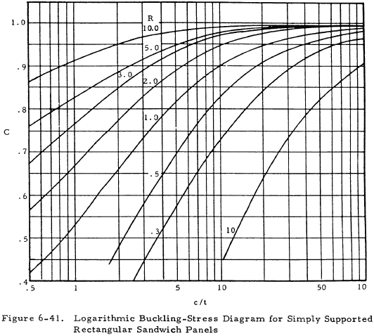
The quantity Fcrf is the buckling stress of the two faces if they were not connected by the core. Use the total thickness of the faces. The coefficient C is obtained from Figure 6-41 and K is a form factor given in Equation (6-41).
The data in Figure 6-41 is given as a family of curves of parameter R which is given in Equation (6-42).
