Analysis of Plates in Bending
This page provides the chapters on the analysis of plates in bending from the "Stress Analysis Manual," Air Force Flight Dynamics Laboratory, October 1986.
Other related chapters from the Air Force "Stress Analysis Manual" can be seen to the right.
- Analysis of Plates in Axial Compression
- Analysis of Plates in Bending
- Shear Buckling of Flat Plates
- Analysis of Curved Plates
- Analysis of Plates - Special Topics
Nomenclature for Plates in Bending
| a | = | plate length |
| b | = | plate width |
| E | = | modulus of elasticity |
| F | = | stress |
| kb | = | bending coefficient |
| P | = | total concentrated load |
| t | = | thickness |
| w | = | unit load |
| W | = | total load |
| η | = | plasticity reduction factor |
| η | = | cladding reduction factor |
| λ | = | buckle half wavelength |
| ν | = | inelastic Poisson's ratio |
| νe | = | elastic Poisson's ratio |
6.4 Bending of Flat Plates
The bending of flat plates in aircraft structures can be caused by both in-plane forces or by normal forces. The quantities of interest in the analysis and design of such plates are the magnitude and location of the maximum stress and the maximum deflection.
The following sections present plots and tables allowing the calculation of these quantities.
6.4.1 Unstiffened Flat Plates in Bending
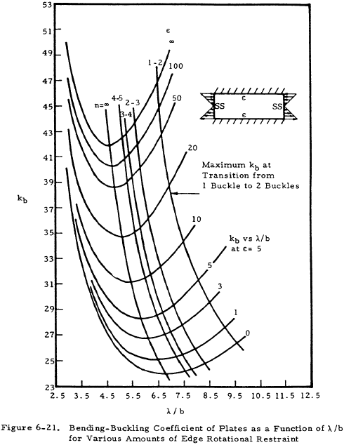
The general buckling relation for plates subjected to in-plane bending is given by Equation (6-20).
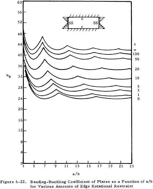
Values of bending coefficient, kb, are given in Figure 6-21 for various edge restraints and the number of buckles versus λ/b, the buckle wave length ratio, and in Figure 6-22 for various edge restraints versus the ratio a/b.
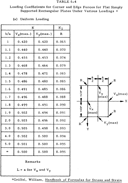
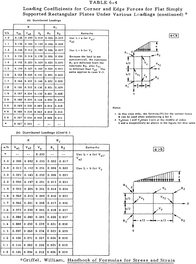
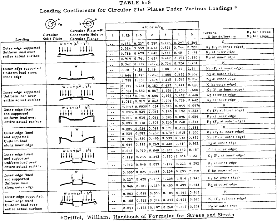
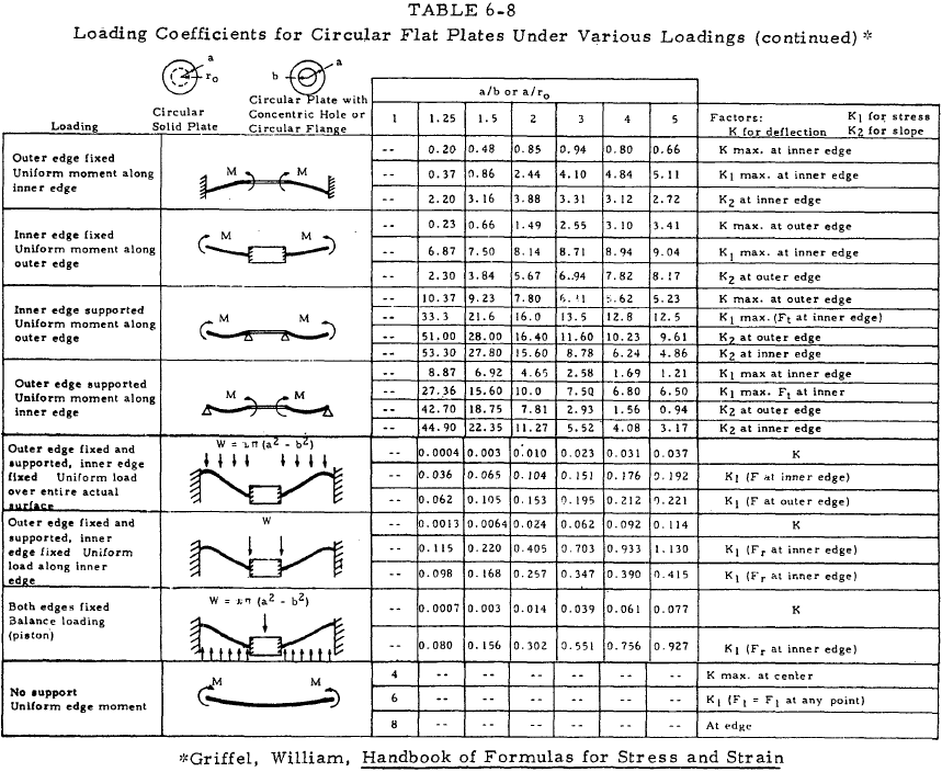
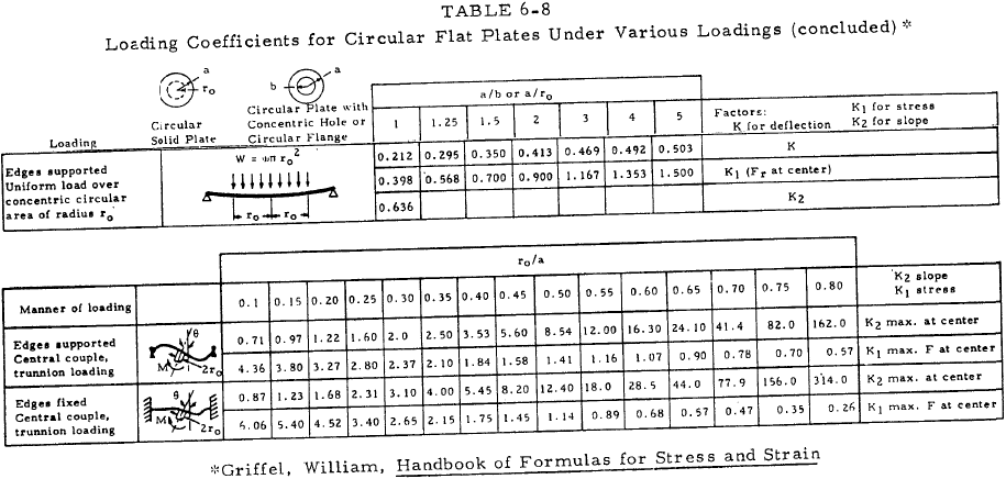
For plates loaded with uniformly distributed normal force, the maximum stress and maximum deflection can be represented by simple relations by the use of a series of constants which depend upon the plate geometry and loading. Tables 6-3 through 6-8 present loading coefficients for use with Equations (6-21) through (6-25).
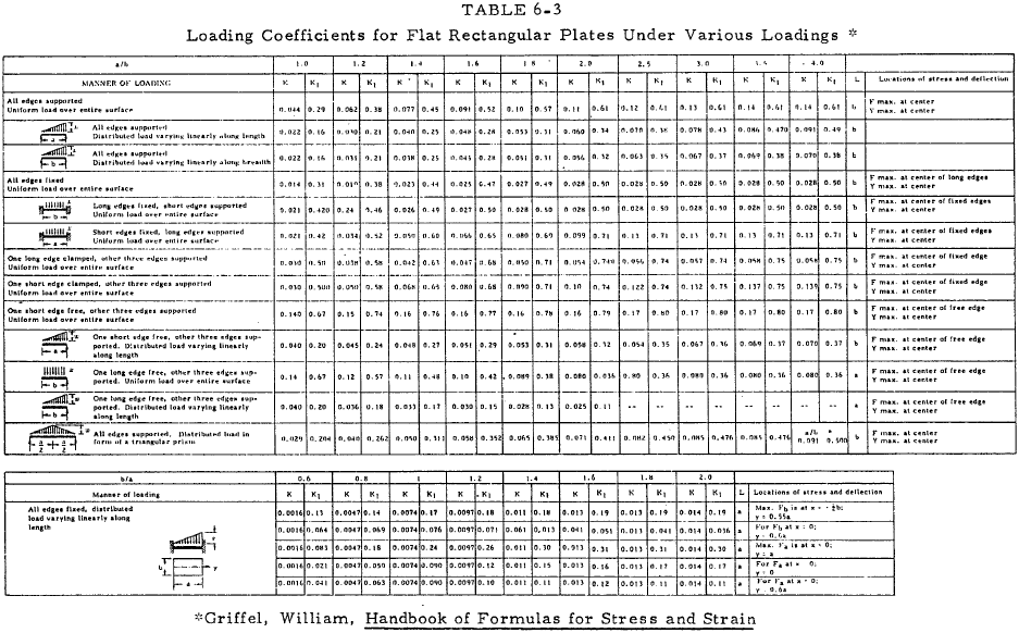
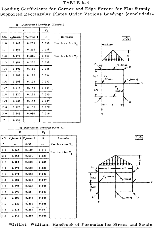
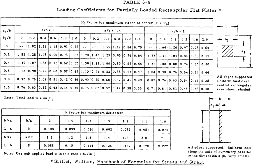
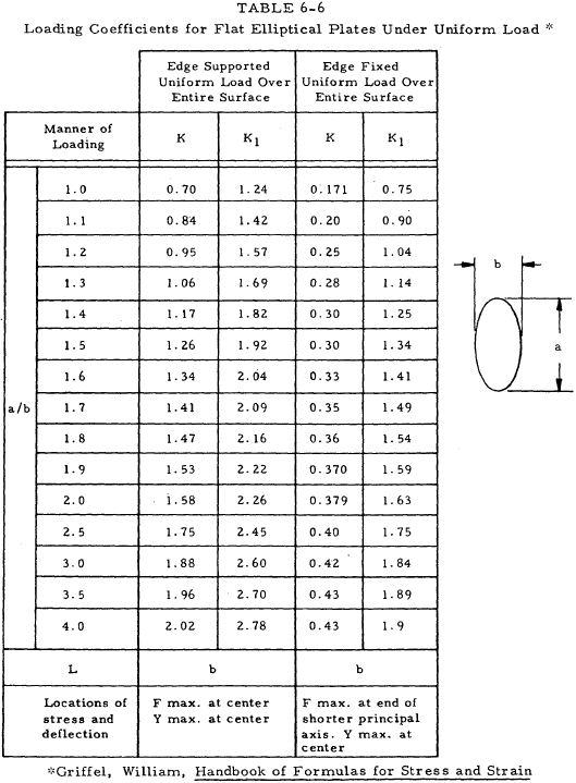
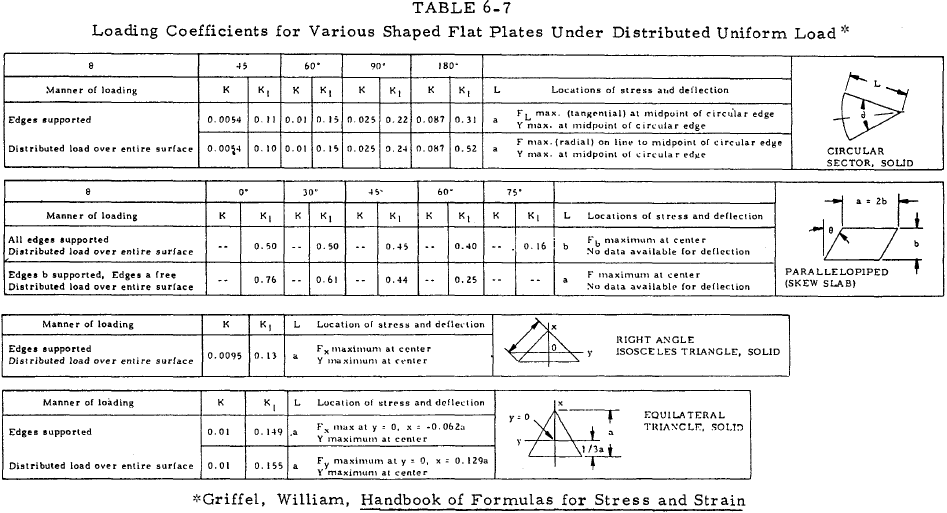
Equation (6-21)(a), (b) pertains to rectangular, square, triangular, and elliptical plates.
| $$ y = { K ~w ~L^4 \over E ~t^3 } $$ | (a) |
| $$ F = { K_1 ~w ~L^2 \over t^2 } $$ | (b) |
Equation (6-22)(a), (b) pertains to corner and edge forces for simply supported rectangular plates.
| $$ R = K_1 w ~a ~b $$ | (a) |
| $$ V = K ~w ~L $$ | (b) |
Equation (6-23)(a), (b) pertains to partially loaded rectangular plates with supported edges.
| $$ y = { K ~w ~L^3 \over E ~t^3 } $$ | (a) |
| $$ F = { K_1 ~W \over t^2 } $$ | (b) |
Equation (6-24)(a), (b), (c) pertains to circular plates.
| $$ y = { K ~W ~a^2 \over E ~t^3 } $$ | (a) |
| $$ F = { K_1 ~W \over t^2 } $$ | (b) |
| $$ \theta = { K_2 ~W ~a \over E ~t^3 } $$ | (c) |
Equation (6-25)(a), (b), (c), (d), (e) pertains to circular plates with end moments.
| $$ y = { K ~M ~a^2 \over E ~t^3 } $$ | (a) |
| $$ F = { K_1 ~M \over t^2 } $$ | (b) |
| $$ \theta = { K_2 ~M ~a \over E ~t^3 } $$ | (c) |
| $$ F = { K_1 ~M \over a ~t^2 } $$ | (d) |
| $$ \theta = { M \over K_2 ~E ~t^3 } $$ | (e) |
Equation (6-25) (d) and (e) applies to trunnion-loaded plates only. (See Table 6-8).
These equations have been developed with a value of 0.3 for Poisson's ratio; however, they may be applied to materials with other values without significant error.
We have a number of structural calculators to choose from. Here are just a few:
6.4.2 Beam-Supported Flat Plates in Bending
The treatment of unstiffened flat plates in Section 6.4.1 included considerations of the edge restraints. These were considered to be rigid in most instances. This section presents methods of analysis which consider the bending of the support beams. Figure 6-23 shows an idealized view of a beam-supported plate. The loading may be either concentrated at the center of the plate or distributed uniformly.
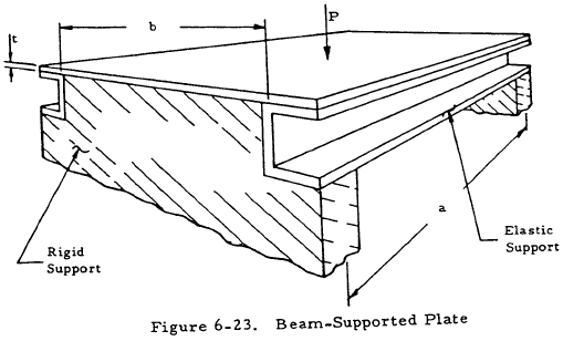
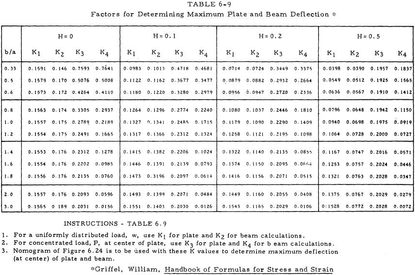
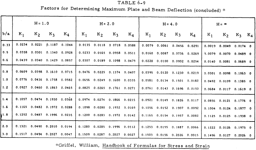
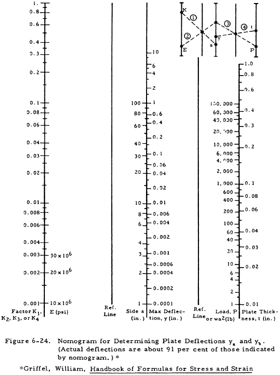
Table 6-9 is used in conjunction with Figure 6-24 to find the maximum of either the plate or supporting beam. The rigidity ratio, H, is given by Equation (6-26).
where \(I_p = a t^3 / 12 \).
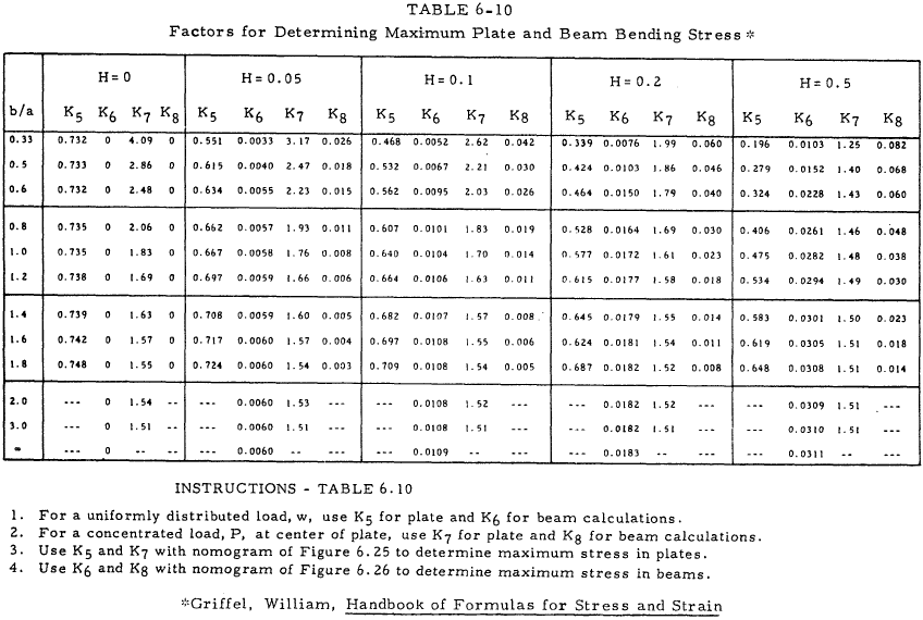
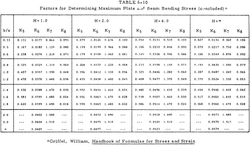
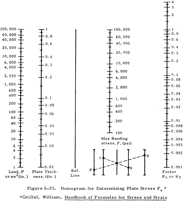
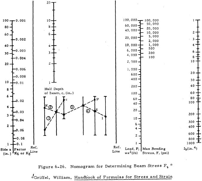
Table 6-10 is used with Figures 6-25 and 6-26 to find the maximum stress in the plate and the beam.
