Analysis of Plates in Axial Compression
This page provides the chapters on the analysis of plates in axial compression from the "Stress Analysis Manual," Air Force Flight Dynamics Laboratory, October 1986.
Other related chapters from the Air Force "Stress Analysis Manual" can be seen to the right.
- Analysis of Plates in Axial Compression
- Analysis of Plates in Bending
- Shear Buckling of Flat Plates
- Analysis of Curved Plates
- Analysis of Plates - Special Topics
6.1 Introduction to Analysis of Plates
This chapter covers the analysis of plates as commonly used in aircraft and missile structures. In general, such plates are classified as thin; that is, deflections are small in comparison with the plate thickness. These plates are subjected to compression, bending, and shear-producing loads. Critical values of these loads produce a wrinkling or buckling of the plate. Such buckling produces unwanted aerodynamic effects on the surface of the airplane. It also may result in the redistribution of loads to other structural members, causing critical stresses to develop. Thus, it is essential that the initial buckling stress of the plate be known. In addition, if the buckling stress is above the proportional limit, the panel will experience ultimate failure very soon after buckling.
The critical buckling of a plate depends upon the type of loading, the plate dimensions, the material, the temperature, and the conditions of edge support.
This chapter considers the various loadings of both flat and curved plates, with and without stiffeners. Single loadings are considered first followed by a discussion of combined loadings. Examples are given to show the use of the analysis methods presented.
6.2 Nomenclature for Analysis of Plates
| a | = | plate length |
| Ast | = | stiffener area |
| b | = | plate width |
| bef | = | effective panel width |
| e | = | strain |
| E | = | modulus of elasticity |
| Es | = | secant modulus |
| Et | = | tangent modulus |
| Es, Et | = | secant and tangent moduli for clad plates |
| f | = | ratio of cladding thickness to total plate thickness |
| F | = | stress |
| F0.7, F0.85 | = | secant yield stress at 0.7E and 0.85E |
| Fcr | = | critical normal stress |
| Fcy | = | compressive yield stress |
| Ff | = | crippling stress |
| Fpl | = | stress at proportional limit |
| FR | = | free (refers to edge fixity) |
| g | = | number of cuts plus number of flanges (Section 6.3.3) |
| k | = | buckling coefficient |
| kc | = | compressive buckling coefficient |
| L' | = | effective column length |
| n | = | shape parameter, number of half waves in buckled plate |
| P | = | total concentrated load |
| ss | = | simply supported |
| t | = | thickness |
| ts | = | skin thickness |
| tw | = | web thickness |
| W | = | total load, potential energy |
| β | = | ratio of cladding yield stress to core stress |
| ϵ | = | ratio of rotational rigidity of plate edge stiffeners |
| η | = | plasticity reduction factor |
| η | = | cladding reduction factor |
| λ | = | buckle half wavelength |
| ν | = | inelastic Poisson's ratio |
| νe | = | elastic Poisson's ratio |
| νp | = | plastic Poisson's ratio |
| ρ | = | radius of gyration |
6.3 Axial Compression of Flat Plates
The compressive buckling stress of a rectangular flat plate is given by Equation (6-1).
The relation is applicable to various types of loadings in both the elastic and the inelastic ranges and for various conditions of edge fixity.
The case of unstiffened plates is treated first and then stiffened plates are discussed.
The edge constraints which are considered vary from simply supported to fixed. A simply supported edge is constrained to remain straight at all loads up to and including the buckling load, but is free to rotate about the center line of the edge. A fixed edge is constrained to remain straight and to resist all rotation. These two conditions define the limits of torsional restraint and are represented by ϵ = 0 for simply supported edges and ϵ = ∞ for fixed edges.
Plates are frequently loaded so that the stresses are beyond the proportional limit of the material. If such is the case, the critical buckling stress is reduced by the factor η, which accounts for changes in k, E, and ν. This allows the values of k, E, and ν to always be the elastic values.
The second reduction factor in Equation (6-1) is the cladding factor η. In order to obtain desirable corrosion resistance, the surface of some aluminum alloys are coated or clad with a material of lower strength, but of better corrosion resistance. The resultant panel may have lower mechanical properties than the basic core material and allowance must be made. Values for the factor η are given in the appropriate sections.
We have a number of structural calculators to choose from. Here are just a few:
6.3.1 Buckling of Unstiffened Flat Plates in Axial Compression
The buckling coefficients and reduction factors of Equation (6-1) applicable to flat rectangular plates in compression are presented in this section.
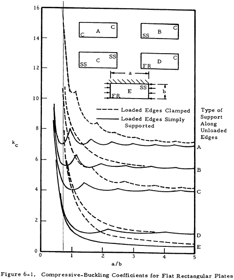
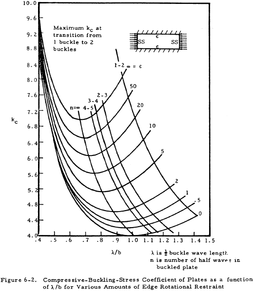
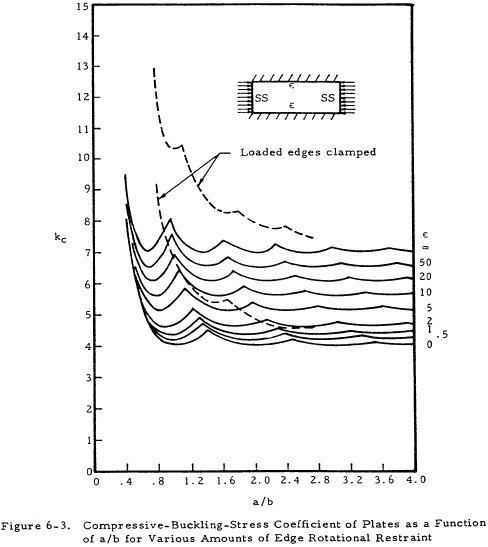
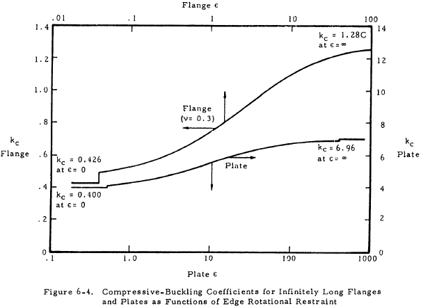
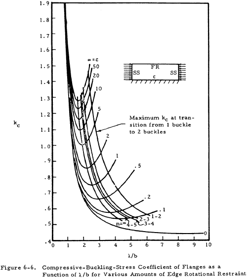
Figures 6-1, 6-2, and 6-3 show the buckling coefficient kc as a function of the ratio a/b and the type of edge restraint; and, in the case of Figure 6-2, the buckle wave length and number of half waves. Figure 6-4 shows kc for infinitely long flanges and plates as a function of the edge restraint only. The edge restraint ratio ϵ is the ratio of the rotational rigidity of plate edge support to the rotational rigidity of the plate.
The condition of unequal rotational support can be treated by Equation (6-2).
The coefficients kc1 and kc2 are obtained by using each value of ϵ independently.
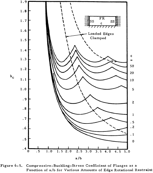
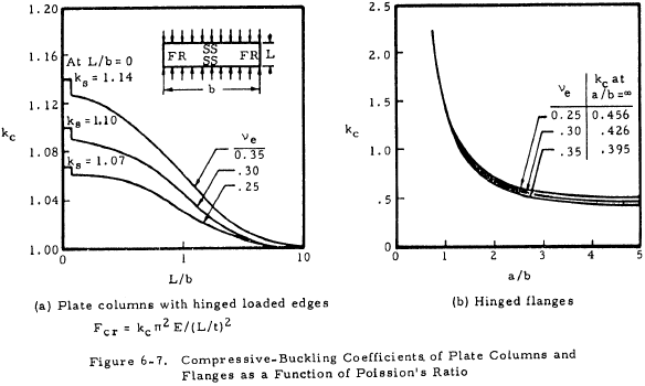
Figures 6-5, 6-6, and 6-7 present kc for flanges. A flange is considered to be a long rectangular plate with one edge free.
The plasticity reduction factor η for a long plate with simply supported edges is given by Equation (6-3).
For a long plate with clamped edges, the factor is given by Equation (6-4).
The value of the inelastic Poisson ratio ν is given by Equation (6-5).
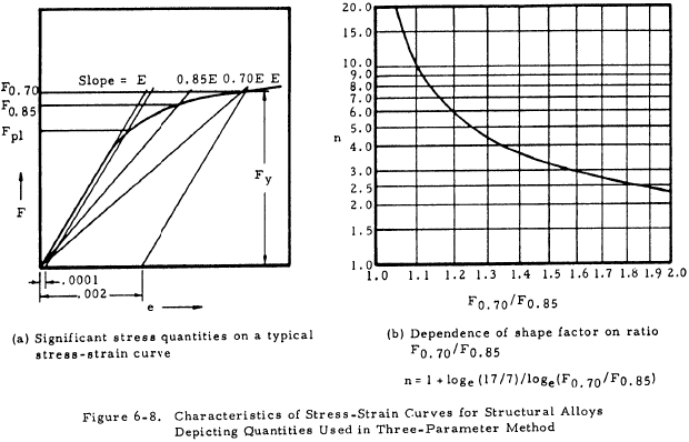
The tangent and secant moduli can be determined from the Ramberg-Osgood relation as shown in Equations (6-6) and (6-7).
Values of E, F0.7, and n must be known for the material under consideration. Figure 6-8 shows the characteristics of stress-strain curves used to determine the shape factor n.
The cladding reduction factor is given by Equation (6-8).
This relation is valid for the range Fcl < Fcr < Fpl. For the plastic range when Fcr > Fpl use Equation (6-9).
The potential energy factor W is given by Equation (6-10).
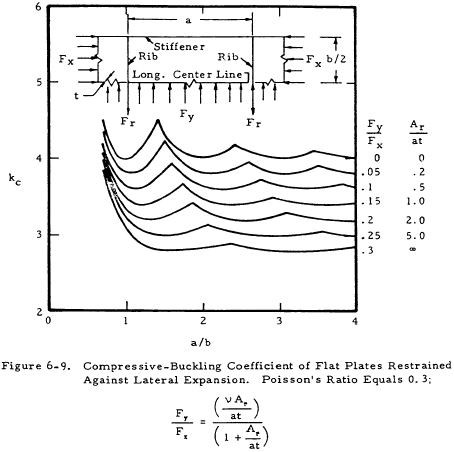
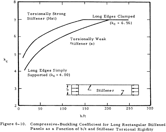
Figures 6-9 and 6-10 present values of kc for plates restrained by stiffeners. This data is included here instead of in the section on stiffened plates because the stiffeners are not a part of the plate. To be noted is the effect of torsional rigidity of the stiffener on the buckling coefficient of the plate.
We have a number of structural calculators to choose from. Here are just a few:
6.3.2 Buckling of Stiffened Flat Plates in Axial Compression
The treatment of stiffened flat plates is the same as that of unstiffened plates except that the buckling coefficient, k, is now also a function of the stiffener geometry. Equation (6-1) is the basic analysis tool for the critical buckling stress.
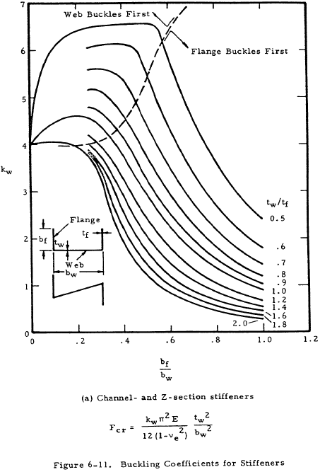
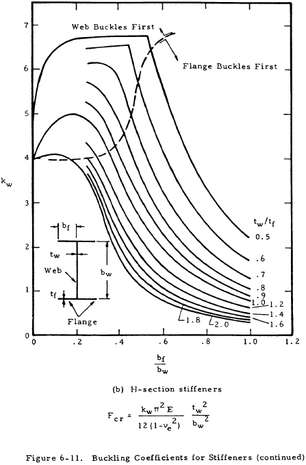
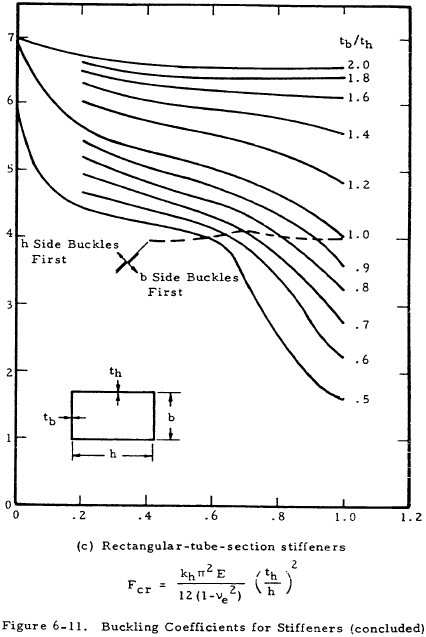
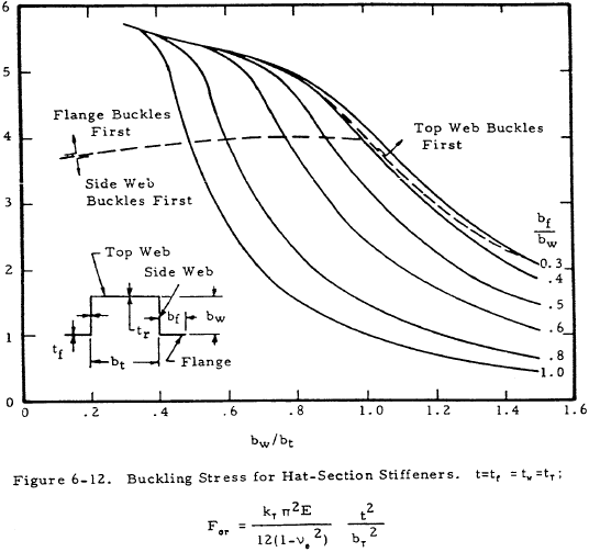
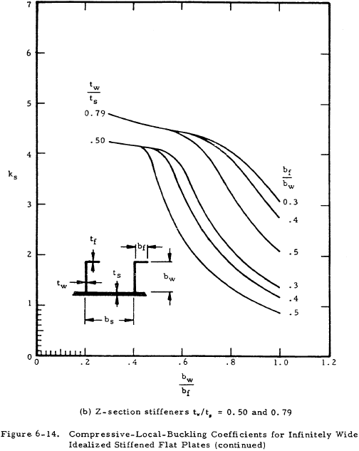
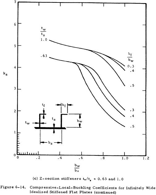
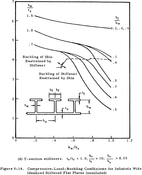
As the stiffener design is a part of the total design, Figures 6-11 and 6-12 present buckling coefficients for various types of stiffeners.
The applicable critical buckling equation is indicated on each figure.
A plasticity reduction factor η is applicable to channel and Z-section stiffeners as given by Equation (6-11).
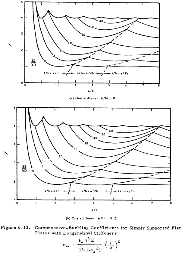
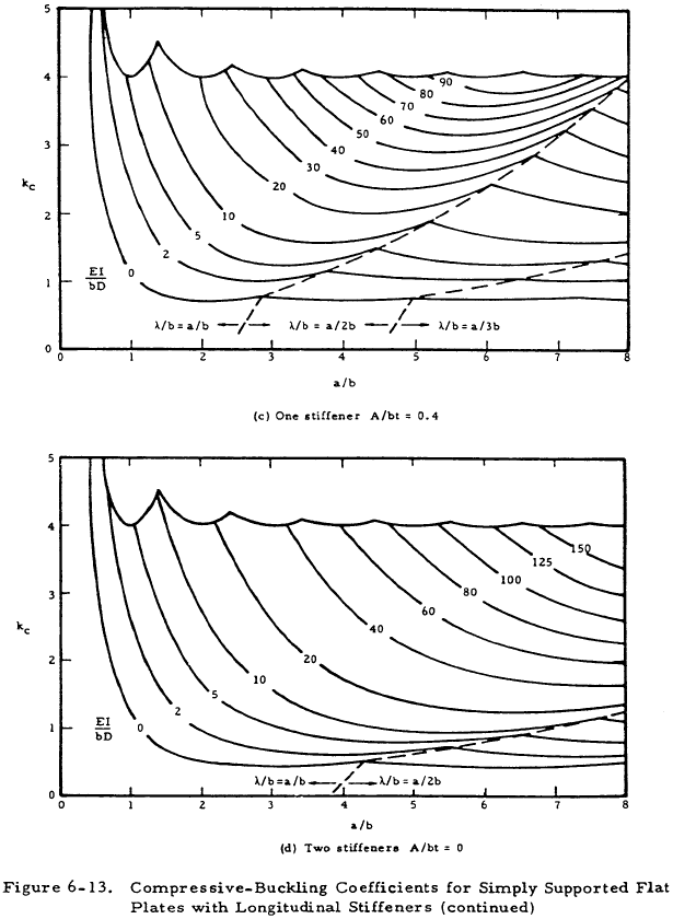
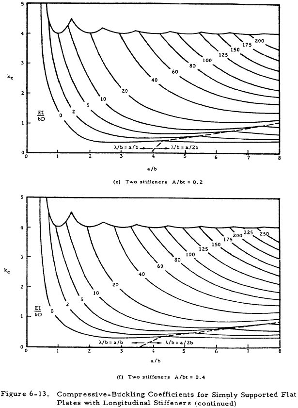
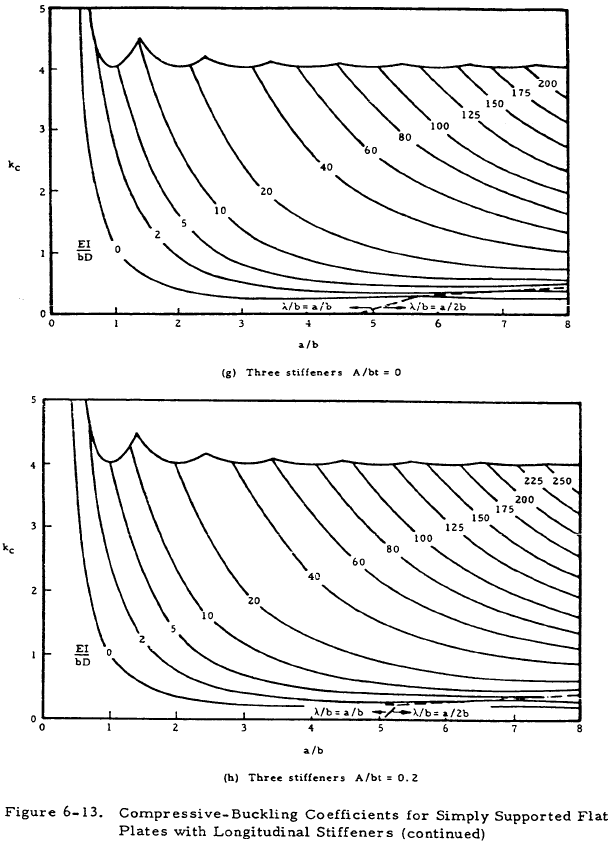
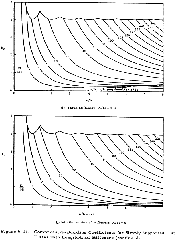
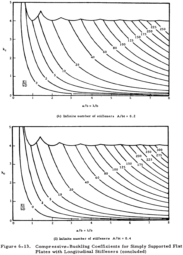
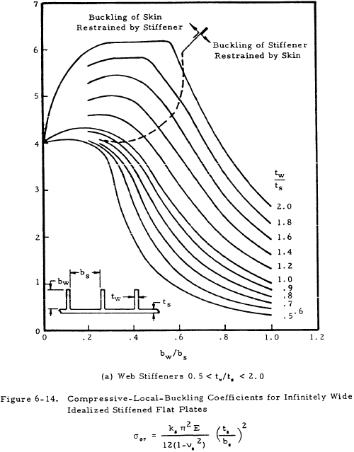
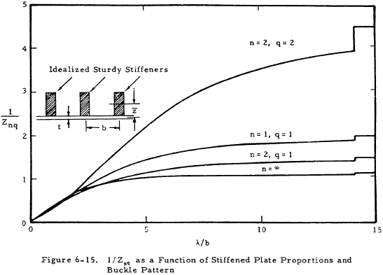
Figures 6-13 and 6-14 present values of the buckling coefficient for longitudinally stiffened plates. The curves of Figure 6-13 are in terms of the plate geometry and the parameter EI/bD for the plate. The curves of Figure 6-13 were based on the assumption that the stiffener section centroid was located at the midsurface of the plate. If the stiffener is located on one side of the plate, as is usually the case, an effective value of (EI/bD) must be determined. Figure 6-15 presents a plot of the function 1/Znq vs λ/b for one, two, or an infinite number of stiffeners to be used in Equation (6-12).
The value of (λ/b) used for Figure 6-15 must be the same as that used in Figure 6-13. This may require an iterative approach as (EI/bD)e may occur at a different value of g in Figure 6-13 than does (EI/bD) at the a/b of the n originally used to enter Figure 6-13.
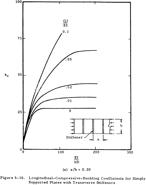
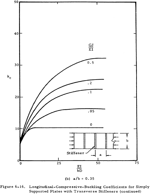
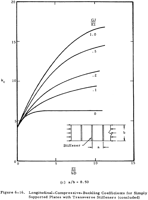
Figure 6-16 presents curves for finding a value for k for plates with transverse stiffeners. It is noted that the stiffeners are allowed to have torsional stiffness in these plots, whereas in Figure 6-13 for axial stiffeners, GJ = 0 for the stiffeners. See Figure 6-10 in Section 6.3.1 for an indication of the effect of stiffener rigidity on the plate buckling coefficient.
We have a number of structural calculators to choose from. Here are just a few:
6.3.3 Crippling Failure of Flat Stiffened Plates in Compression
For stiffened plates having slenderness ratios L'/ρ ≤ 20, considered to be short plates, the failure mode is crippling rather than buckling when loaded in compression. The crippling strength of individual stiffening elements is considered in Chapter 2, Column Analysis. The crippling strength of panels stiffened by angle-type elements is given by Equation (6-13).
For more complex stiffeners such as Y sections, the relation of Equation (6-14) is used to find a weighted value of tw.
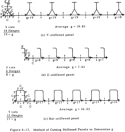
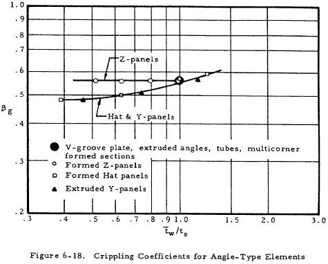
where a1 and t1 are the length and thickness of the cross-sectional elements of the stiffener. Figure 6-17 shows the method of determining the value of g used in Equation (6-13) based on the number of cuts and flanges of the stiffened panels. Figure 6-18 gives the coefficient βg for various stiffening elements.
If the skin material is different from the stiffener material, a weighted value of Fcy given by Equation (6-15) should be used.
Here, t is the effective thickness of the stiffened panel.
The above relations assume the stiffener-skin unit to be formed monolithically; that is, the stiffener is an integral part of the skin. For riveted construction, the failure between the rivets must be considered. The interrivet buckling stress is determined as to plate buckling stress, and is given by Equation (6-16).
Values of ϵ, the edge fixity, are given in Table 6-1.
| Fastener Type | (Fixity-Coefficient) ϵ |
|---|---|
| Flathead rivet | 4 |
| Spotwelds | 3.5 |
| Brazier-head rivet | 3 |
| Countersunk rivet | 1 |
After the interrivet buckling occurs, the resultant failure stress of the panel is given by Equation (6-17).
Here the value bef is the effective width of skin corresponding to the interrivet buckling stress F1. The failure stress of short riveted panels by wrinkling can be determined. The following quantities are used:
| F fst | crippling strength of stringer alone (see Chapter 2, Column Analysis) |
| F w | wrinkling strength of the skin |
| F f | crippling strength of a similar monolithic panel |
| F fr | strength of the riveted panel |
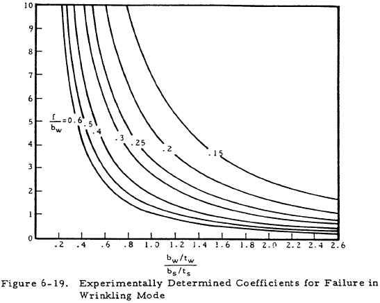
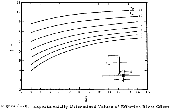
The wrinkling strength of the skin can be determined from Equation (6-18) and Figure 6-19. Here, f is the effective rivet offset distance given in Figure 6-20. This was obtained for aluminum rivets having a diameter greater than 90% of the skin thickness.
Now, based on the stringer stability, the strength of the panel can be calculated. Table 6-2 shows the various possibilities and solutions.
| Stringer Stability | Panel Strength |
|---|---|
| F fst ≥ F w -- stable | F fr = F w |
| F fst < F w -- unstable | $$ \overline{F}_{fr} = { \overline{F}_w b_s t_s + \overline{F}_{fst} A_{st} \over b_s t_s + A_{st} } $$ |
It is noted that in no case should F sr > F f . Thus, the lower of these two values should be used.
The use of the coefficient kw is based upon aluminum alloy data for other materials. The procedure is to use Equation (6-19) for the panel crippling strength.
