Analysis of Curved Plates
This page provides the chapters on the analysis of curved plates from the "Stress Analysis Manual," Air Force Flight Dynamics Laboratory, October 1986.
Other related chapters from the Air Force "Stress Analysis Manual" can be seen to the right.
Nomenclature
| a | = | plate length |
| b | = | plate width |
| C | = | compressive buckling coefficient for curved plates |
| E | = | modulus of elasticity |
| Es | = | secant modulus |
| Et | = | tangent modulus |
| F0.7, F0.85 | = | secant yield stress at 0.7E and 0.85E |
| Fcr | = | critical normal stress |
| Fcrs | = | critical shear stress |
| kc | = | compressive buckling coefficient |
| r | = | radius of curvature |
| t | = | thickness |
| Zb | = | length range parameter b2(1 - νe2)1/2/ rt |
| η | = | plasticity reduction factor |
| ν | = | inelastic Poisson's ratio |
| νe | = | elastic Poisson's ratio |
6.6 Axial Compression of Curved Plates
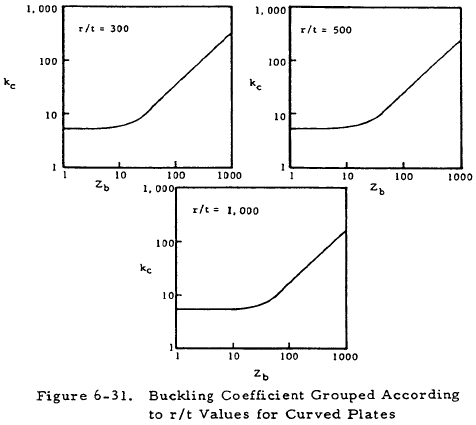
The radius of curvature of curved plates determines the method to be used to analyze their buckling stress. For large curvature (b2/ rt < 1), they may be analyzed as flat plates by using the relations in Section 6.3. For elastic stresses in the transition length and width ranges, Figure 6-31 may be used to find the buckling coefficient for use in Equation (6-31).
For sharply curved plates, (b2/ rt > 100), Equations (6-32) and (6-33) can be used.
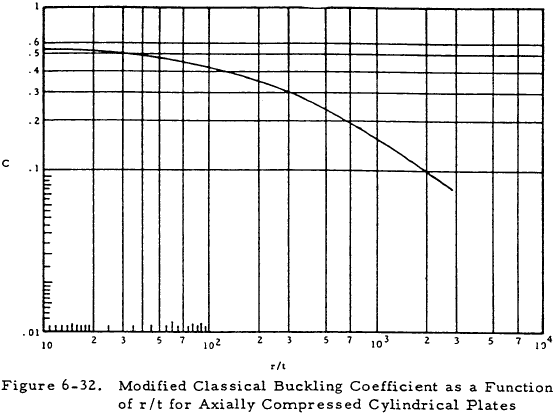
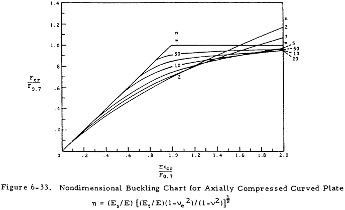
Figure 6-32 gives values of C in terms of r/t. Figure 6-33 gives η in a nondimensional form. Here the quantity ϵcr = Ct/r.
We have a number of structural calculators to choose from. Here are just a few:
6.7 Shear Loading of Curved Plates
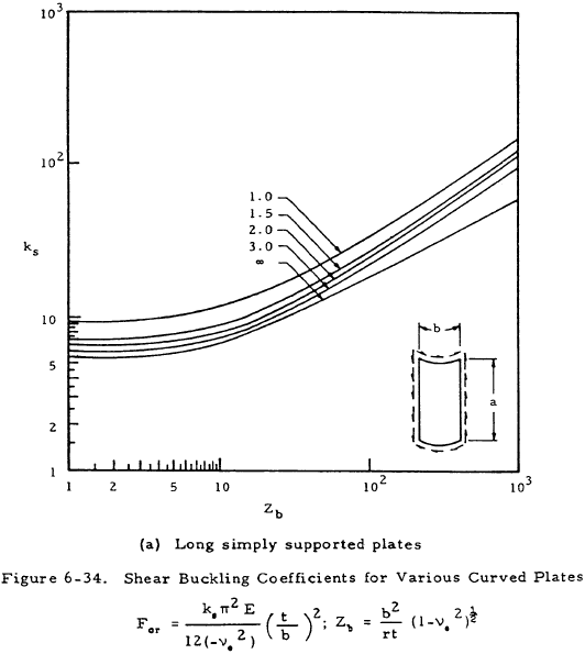
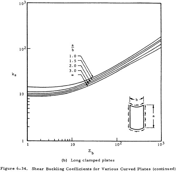
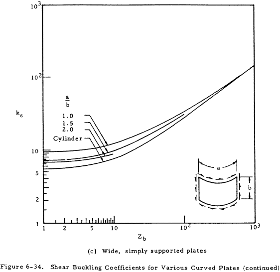
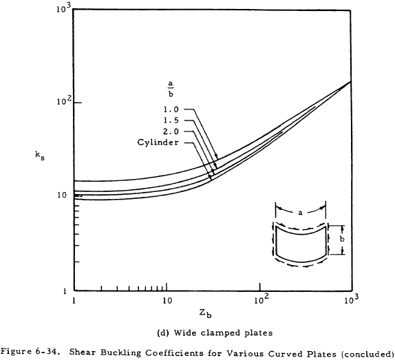
Large radius curved plates (b2/ rt < 1) loaded in shear may be analyzed as flat plates by the methods of Section 6.5. For transition length plates (1 < b2/ rt < 30), Figure 6-34 can be used to find ks for use in Equation (6-34).
For (b2/ rt > 30), Equation (6-35) may be used.
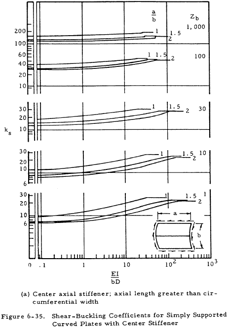
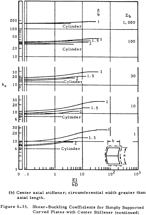
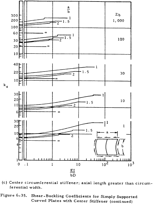
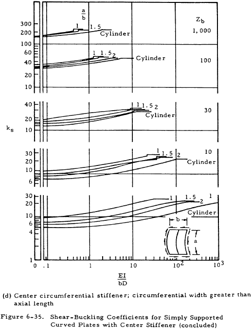
Curved plates under shear loading with stiffeners can be analyzed by using Figure 6-35 for the value of the buckling coefficient ks. Both axial stiffeners and circumferential stiffeners are treated.
