Membranes
This page provides the chapter on the analysis of membranes from the "Stress Analysis Manual," Air Force Flight Dynamics Laboratory, October 1986.
7.1 Introduction to Membranes
A membrane may be defined to be a plate that is so thin that it may be considered to have no bending rigidity. The only stresses present are in the plane of the surface and are uniform throughout the thickness of the membrane.
Section 7.3 of this chapter treats of circular membranes, and Section 7.5 deals with square and rectangular membranes.
7.2 Nomenclature for Membranes
| a | = | longitudinal dimension of membrane |
| D | = | diameter |
| E | = | modulus of elasticity |
| f | = | calculated stress |
| fmax | = | calculated maximum stress |
| n1-n7 | = | coefficients given in Figure 7-9 |
| p | = | pressure |
| R | = | outside radius of circular membrane |
| r | = | cylindrical coordinate |
| t | = | thickness of membrane |
| x, y | = | rectangular coordinates |
| δ | = | deflection |
| δc | = | center deflection of circular membrane |
| μ | = | Poisson's ratio |
7.3 Circular Membranes
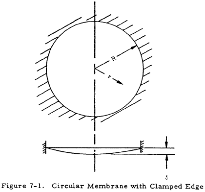
Figure 7-1 shows two views of a circular membrane with the clamped edge under a uniform pressure, p.
The maximum deflection of this membrane is at the center and is given by
The deflection of the membrane at a distance, r, from the center is
The stress at the center of this membrane is
while that at the edge is
7.4 Sample Problem - Circular Membranes
Given: The circular membrane shown in Figure 7-2
Find: The center deflection and the stresses at the center and at the edge of the membrane.
Solution:
$$ {p \over E} \left({ D \over t }\right)^4 = { 10 \over 10 \times 10^6 } \left({ 15 \over 0.1 }\right)^4 = 506 $$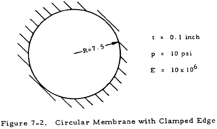
From Section 7.5.3.2, a square plate, for which p/E (b/t)4 is greater than 250, may be considered to be a membrane. Assuming this to be approximately true for a circular plate with D used in the relation instead of b, the given plate may be treated as a membrane.
From Equation (7-1), the center deflection of the given membrane is
From Equation (7-3), the stress at the center of the membrane is
From Equation (7-4), the stress at the edge of the membrane is
We have a number of structural calculators to choose from. Here are just a few:
7.5 Rectangular Membranes
For purposes of analysis, rectangular membranes may be divided into two classes: long rectangular membranes where the ratio of length to width (a/b) is greater than five, and short rectangular membranes where this ratio is less than five.
7.5.1 Long Rectangular Membranes
Figure 7-3 shows a long rectangular membrane (a/b > 5) clamped along all four sides.
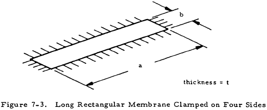
The deflection and stress at the center of such a plate are approximately the same as those in a long membrane clamped along the two long sides. Such a membrane is shown in its deflected position in Figure 7-4.
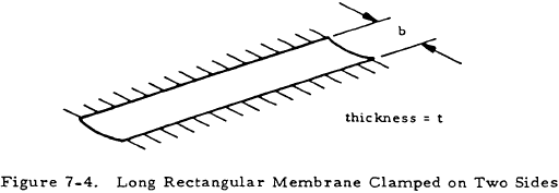
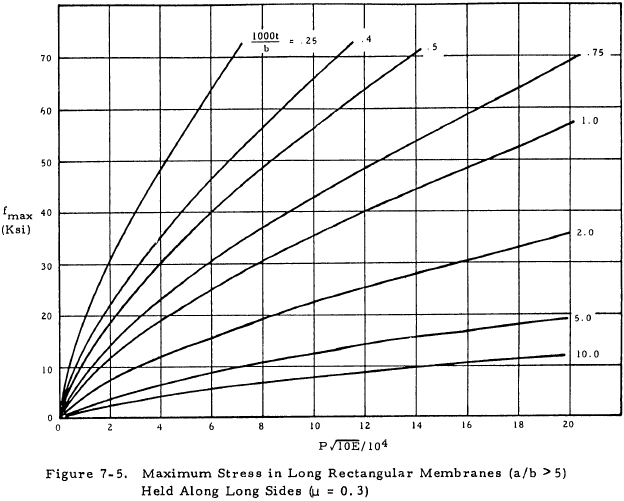
The maximum stress and center deflection of the membrane in Figure 7-4 under uniform pressure pare given by Equations (7-5) and (7-6).
These equations are presented graphically in Figures 7-5 and 7-6 for μ = 0.3.
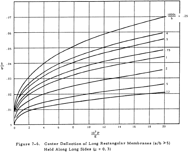
A long rectangular plate may be considered to be a membrane if p/E (b/t)4 is greater than 100.
7.5.2 Sample Problem - Long Rectangular Membrane
Given: The membrane shown in Figure 7-7.
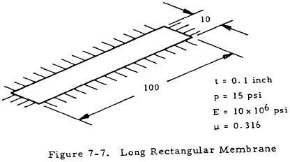
Find: The maximum stress and center deflection
Solution:
$$ {p \over E} \left({b \over t}\right)^4 = {15 \over 10 \times 10^6} \left({10 \over 0.1}\right)^4 = 150 $$Since this quantity is greater than 100, the given plate may indeed be considered to be a membrane.
From Equation (7-5),
From Equation (7-6),
Thus,
$$ \delta = 0.0185 ~b = 0.0185 (10) = 0.185 ~\text{in} $$For quick calculations, the graphs in Figures 7-5 and 7-6 could have been used. However, this procedure would give answers that are not theoretically exact since these graphs are based on a Poisson's ratio of 0.3 rather than 0.316.
We have a number of structural calculators to choose from. Here are just a few:
7.5.3 Short Rectangular Membranes
7.5.3.1 Theoretical Results for Short Rectangular Membranes
Figure 7-8 shows a short rectangular membrane (a/b < 5) clamped on four sides under a uniform pressure p.
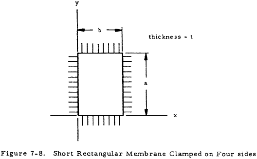
The deflection at the center of such a membrane is
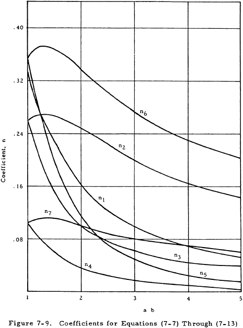
where n1 is given in Figure 7-9.
The stresses at various locations on short rectangular membranes are given by the following equations for which the values of the coefficients n2 through n7 are given in Figure 7-9.
Center of plate (x = b/2, y = a/2)
Center of short side (x = b/2, y = 0)
Center of long side (x = 0, y = a/2)
It should be noted that the maximum membranes stress occurs at the center of the long side of the plate.
7.5.3.2 Applicability of Theoretical Results for Short Rectangular Membranes
Figures 7-10 and 7-11 give the deflections of plates with various length-to-width ratios obtained from the equations in Section 7.5.3.1 and compare these deflections with experimental values for 10-inch-wide aluminum plates.
For square plates (a/b = 1.0), the thick plate theory should be used for values of (p/E) (b/t)4 from 0 to 100. If 100 < (p/E) (b/t)4 < 250, no theoretical method compares closely with test although the membrane theory should be used for conservative results. If (p/E) (b/t)4 is greater than 250, the membrane theory produces results that compare closely with experiments for square plates.
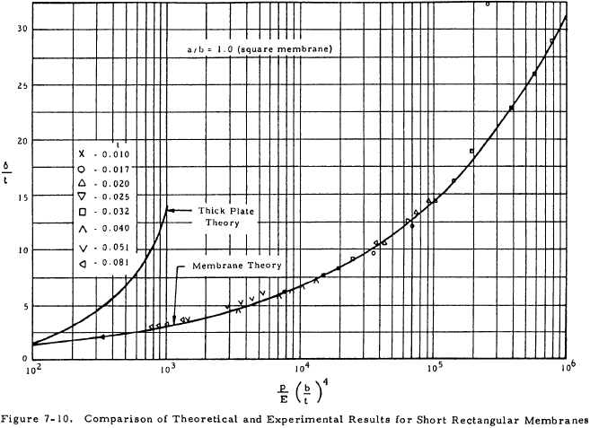
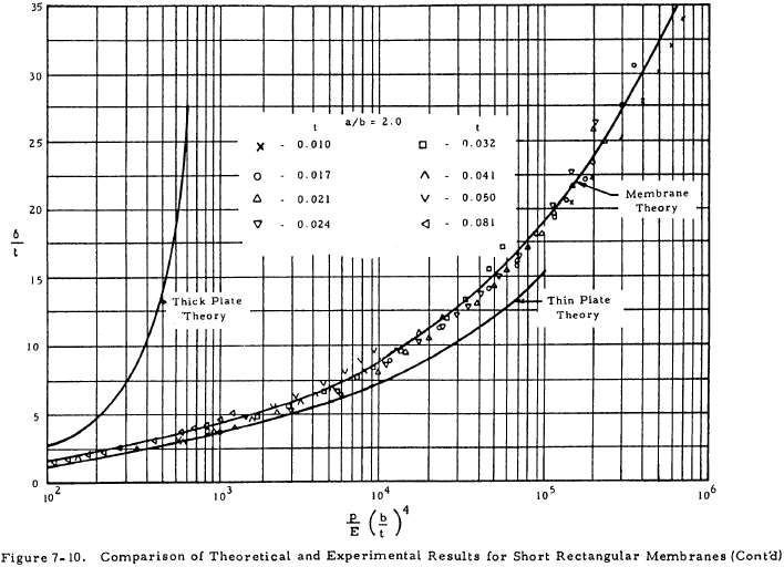
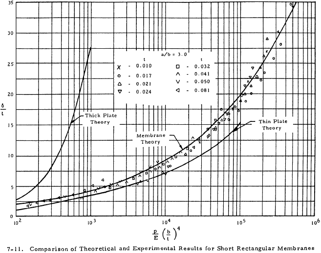
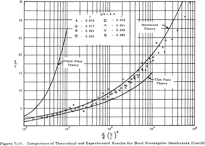
A rectangular plate (a/b > 1.0) may be considered as a membrane if (p/E) (b/t)4 > 100, with results becoming more conservative as a/b decreases.
7.5.3.3 Sample Problem - Short Rectangular Membranes
Given: The membrane shown in Figure 7-12
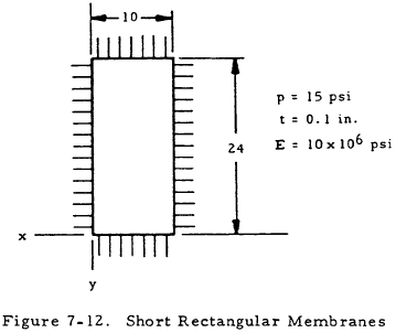
Find: The center deflection and stresses
Solution:
$$ \left({p \over E}\right) \left({b \over t}\right)^4 = {15 \over 10^7} \left({10 \over 0.1}\right)^4 = 150 $$Since this value is greater than 100, the given plate may be treated by membrane equations, according to Section 7.5.3.2.
$$ {a \over b} = {24 \over 10} = 2.4 $$From Figure 7-9:
| n1 = 0.130 | n5 = 0.077 |
| n2 = 0.230 | n6 = 0.311 |
| n3 = 0.080 | n7 = 0.090 |
| n4 = 0.026 |
From Equation (7-7), the deflection of the center of the membrane is
From Equation (7-8) through (7-13), the stresses in the membrane are as follows:
Center of plate (x = 5, y = 12)
Center of short side (x = 5, y = 0)
Center of long side (x = 0, y = 12)
The greatest stress is 15,750 psi at the center of the long side.
