Material Selection
This page provides the chapters on material selection considerations from the "DOE Fundamentals Handbook: Material Science," DOE-HDBK-1017/1-93, U.S. Department of Energy, Jan 1993.
Other related chapters from the "DOE Fundamentals Handbook: Material Science" can be seen to the right.
- Structure of Metals
- Properties of Metals
- Material Selection
- Thermal Stress
- Brittle Fracture
Properties Considered When Selecting Materials
There are many different kinds of materials used in the construction of a nuclear facility. Once constructed, these materials are subjected to environments and operating conditions that may lead to material problems. This chapter discusses considerations for selection and application of plant materials.
Overview
During the selection and application of materials used for construction of a nuclear facility, many different material properties and factors must be considered depending upon the requirements for each specific application. Generally, these consist of both non-fuel reactor materials, used for structural and component construction, and fuel materials. This chapter discusses some of the considerations used in the selection process for plant materials including material properties, fuel, fuel cladding, reflector material, control materials, and shielding materials.
Material Properties
The following properties are considered when selecting materials that are to be used in the construction of nuclear facilities.
Machinability
Components may be formed by removing metal "chips" by mechanical deformation. This process is referred to as machining. Machinability describes how a metal reacts to mechanical deformation by removing chips, with respect to the amount of metal effectively removed and the surface finish attainable. The mechanical properties of the metal will be the factors that influence the machinability of a metal. Many components used in nuclear reactor construction use machined parts that require very close tolerances and very smooth surfaces. Thus, machinability becomes an important consideration when choosing materials for manufacturing these parts.
Formability
Components may be formed by processes such as rolling or bending, which may cause some parts of the metal to expand more than others. Formability of a material is its ability to withstand peripheral expansion without failure or the capacity of the material to be to manufactured into the final required shape. This becomes important in selecting materials that have to be made into specific shapes by such means as rolling or bending and still retain their required strength.
Ductility
Ductility is the plastic response to tensile force. Plastic response, or plasticity, is particularly important when a material is to be formed by causing the material to flow during the manufacture of a component. It also becomes important in components that are subject to tension and compression, at every temperature between the lowest service temperature and the highest service temperature. Ductility is essential for steels used in construction of reactor pressure vessels. Ductility is required because the vessel is subjected to pressure and temperature stresses that must be carefully controlled to preclude brittle fracture. Brittle fracture is discussed in more detail in Module 4, Brittle Fracture.
Stability
Stability of a material refers to its mechanical and chemical inertness under the conditions to which it will be subjected. Nuclear plants have a variety of environments to which materials are subjected. Some of these environments, such as high temperatures, high acid, high radiation, and high pressure, can be considered extreme and harsh; therefore, the stability of the materials selected for service in these areas is a major consideration.
Corrosion mechanisms can become very damaging if not controlled. They are identified in Module 2, Properties of Metals. High corrosion resistance is desirable in reactor systems because low corrosion resistance leads to increased production of corrosion products that may be transported through the core. These products become irradiated and contaminate the entire system. This contamination contributes to high radiation levels after shutdown. For these reasons, corrosion resistant materials are specially chosen for use in the primary and secondary coolant systems.
Availability
The availability of a material used in the construction of nuclear plants refers to the ease with which a material can be obtained and its cost.
Fabricability
Fabricability is a measure of the ease with which a material can be worked and made into desirable shapes and forms. Many components of a nuclear reactor have very complicated shapes and forms and require very close tolerances. Therefore, fabricability is an important consideration in the manufacturing of these components.
Heat Transfer
Good heat transfer properties are desirable from the fuel boundary to the coolant in order that the heat produced will be efficiently transferred.
For a constant amount of heat transfer, a degraded heat transfer characteristic requires higher fuel temperature, which is not desirable. Therefore, desirable heat transfer properties in the selection of reactor materials, especially those used as core cladding and heat exchanger tubes, are a major consideration.
Cost
Capital costs for building a typical nuclear facility can be millions of dollars. A major portion of the cost is for plant material; therefore, cost is an important factor in the selection of plant materials.
Mechanical Strength
Preventing release of radioactive fission products is a major concern in the design, construction, and operation of a nuclear plant. Therefore, mechanical strength plays an important role in selecting reactor materials. High mechanical strength is desirable because of its possible degradation due to radiation damage and the need to contain the radioactive liquids and fuel.
We have a number of structural calculators to choose from. Here are just a few:
Plant Material Problems
Material problems in a nuclear reactor plant can be grouped into two categories, one concerning the nuclear reactor core and one that will apply to all plant materials. This chapter discusses specific material problems associated with fatigue failure, work hardening, mechanical forces applied to materials, stress, and strain.
Fatigue Failure
The majority of engineering failures are caused by fatigue. Fatigue failure is defined as the tendency of a material to fracture by means of progressive brittle cracking under repeated alternating or cyclic stresses of an intensity considerably below the normal strength. Although the fracture is of a brittle type, it may take some time to propagate, depending on both the intensity and frequency of the stress cycles. Nevertheless, there is very little, if any, warning before failure if the crack is not noticed. The number of cycles required to cause fatigue failure at a particular peak stress is generally quite large, but it decreases as the stress is increased. For some mild steels, cyclical stresses can be continued indefinitely provided the peak stress (sometimes called fatigue strength) is below the endurance limit value.
A good example of fatigue failure is breaking a thin steel rod or wire with your hands after bending it back and forth several times in the same place. Another example is an unbalanced pump impeller resulting in vibrations that can cause fatigue failure.
The type of fatigue of most concern in nuclear power plants is thermal fatigue. Thermal fatigue can arise from thermal stresses produced by cyclic changes in temperature. Large components like the pressurizer, reactor vessel, and reactor system piping are subject to cyclic stresses caused by temperature variations during reactor startup, change in power level, and shutdown.
Fundamental requirements during design and manufacturing for avoiding fatigue failure are different for different cases. For a pressurizer, the load variations are fairly low, but the cycle frequency is high; therefore, a steel of high fatigue strength and of high ultimate tensile strength is desirable. The reactor pressure vessel and piping, by contrast, are subjected to large load variations, but the cycle frequency is low; therefore, high ductility is the main requirement for the steel. Thermal sleeves are used in some cases, such as spray nozzles and surge lines, to minimize thermal stresses. Although the primary cause of the phenomenon of fatigue failure is not well known, it apparently arises from the initial formation of a small crack resulting from a defect or microscopic slip in the metal grains. The crack propagates slowly at first and then more rapidly when the local stress is increased due to a decrease in the load-bearing cross section. The metal then fractures. Fatigue failure can be initiated by microscopic cracks and notches, and even by grinding and machining marks on the surface; therefore, such defects must be avoided in materials subjected to cyclic stresses (or strains). These defects also favor brittle fracture, which is discussed in detail in Module 4, Brittle Fracture.
Plant operations are performed in a controlled manner to mitigate the effects of cyclic stress. Heatup and cooldown limitations, pressure limitations, and pump operating curves are all used to minimize cyclic stress. In some cases, cycle logs may be kept on various pieces of equipment. This allows that piece of equipment to be replaced before fatigue failure can take place.
Work (Strain) Hardening
Work hardening is when a metal is strained beyond the yield point. An increasing stress is required to produce additional plastic deformation and the metal apparently becomes stronger and more difficult to deform.
Stress-strain curves are discussed in Module 2, Properties of Metals. If true stress is plotted against true strain, the rate of strain hardening tends to become almost uniform, that is, the curve becomes almost a straight line, as shown in Figure 1. The gradient of the straight part of the line is known as the strain hardening coefficient or work hardening coefficient, and is closely related to the shear modulus (about proportional). Therefore, a metal with a high shear modulus will have a high strain or work hardening coefficient (for example, molybdenum). Grain size will also influence strain hardening. A material with small grain size will strain harden more rapidly than the same material with a larger grain size. However, the effect only applies in the early stages of plastic deformation, and the influence disappears as the structure deforms and grain structure breaks down.
Work hardening is closely related to fatigue. In the example on fatigue given above, bending the thin steel rod becomes more difficult the farther the rod is bent. This is the result of work or strain hardening. Work hardening reduces ductility, which increases the chances of brittle failure.
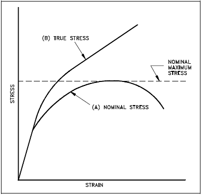
Work hardening can also be used to treat material. Prior work hardening (cold working) causes the treated material to have an apparently higher yield stress. Therefore, the metal is strengthened.
Creep
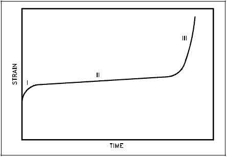
At room temperature, structural materials develop the full strain they will exhibit as soon as a load is applied. This is not necessarily the case at high temperatures (for example, stainless steel above 1000°F or zircaloy above 500°F). At elevated temperatures and constant stress or load, many materials continue to deform at a slow rate. This behavior is called creep. At a constant stress and temperature, the rate of creep is approximately constant for a long period of time. After this period of time and after a certain amount of deformation, the rate of creep increases, and fracture soon follows. This is illustrated in Figure 2.
Initially, primary or transient creep occurs in Stage I. The creep rate, (the slope of the curve) is high at first, but it soon decreases. This is followed by secondary (or steady-state) creep in Stage II, when the creep rate is small and the strain increases very slowly with time. Eventually, in Stage III (tertiary or accelerating creep), the creep rate increases more rapidly and the strain may become so large that it results in failure.
The rate of creep is highly dependent on both stress and temperature. With most of the engineering alloys used in construction at room temperature or lower, creep strain is so small at working loads that it can safely be ignored. It does not become significant until the stress intensity is approaching the fracture failure strength. However, as temperature rises creep becomes progressively more important and eventually supersedes fatigue as the likely criterion for failure. The temperature at which creep becomes important will vary with the material.
For safe operation, the total deformation due to creep must be well below the strain at which failure occurs. This can be done by staying well below the creep limit, which is defined as the stress to which a material can be subjected without the creep exceeding a specified amount after a given time at the operating temperature (for example, a creep rate of 0.01 in 100,000 hours at operating temperature). At the temperature at which high-pressure vessels and piping operate, the creep limit generally does not pose a limitation. On the other hand, it may be a drawback in connection with fuel element cladding. Zircaloy has a low creep limit, and zircaloy creep is a major consideration in fuel element design. For example, the zircaloy cladding of fuel elements in PWRs has suffered partial collapse caused by creep under the influence of high temperature and a high pressure load. Similarly, creep is a consideration at the temperatures that stainless-steel cladding encounters in gas-cooled reactors and fast reactors where the stainless-steel cladding temperature may exceed 540°C.
PDH Classroom offers a continuing education course based on this material selection reference page. This course can be used to fulfill PDH credit requirements for maintaining your PE license.
Now that you've read this reference page, earn credit for it!
