Helical Springs
This page provides the section on helical springs from the "Stress Analysis Manual," Air Force Flight Dynamics Laboratory, October 1986.
Nomenclature
| b | = | width of section |
| D | = | diameter |
| fs | = | calculated shear stress |
| G | = | modulus of elasticity in shear |
| n | = | number of active spring coils |
| P | = | axial load |
| r | = | radius |
| δ | = | spring deflection |
1.5.4 Helical Springs
The primary stresses in the wire of a helical spring are due to torsion. Section 1.5.4.1 treats helical springs composed of round wire, and those composed of square wire are treated in Section 1.5.4.2.
1.5.4.1 Helical Springs of Round Wire
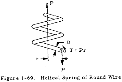
Figure 1-69 shows a helical spring made of round wire under an axial load, P. If the spring radius (r) is much greater than the wire diameter (D), the wire may be treated as a straight round beam under a torsional load, Pr, as indicated in Figure 1-69. Superposing the stress due to torsion of the wire on the uniform shear stress due to direct shear (4P/πD2), the following equation for the maximum shear stress in the spring may be obtained:
In the cases of heavy coil springs composed of wire with a relatively large diameter, D, in comparison to r, the initial curvature of the spring must be accounted for. This is done in the following equation:
where
This equation reduces to Equation (1-83) as r/D becomes large.
The total deflection (δ) of a round spring of n free coils is given by
This equation neglects the deflection due to direct shear which is given by
This portion of the deformation, however, is generally negligible compared to the value of δ given by Equation (1-86) and is thus generally ignored.
All of the equations in this section apply to both compression and tension springs, and in both cases the maximum shear stress occurs at the inside of the wire.
We have a number of structural calculators to choose from. Here are just a few:
1.5.4.2 Helical Springs of Square Wire
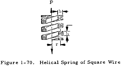
Figure 1-70 shows a helical spring made of square wire under an axial load, P. The maximum shear stress in the square wire is given by
where
The total deflection of such a spring is given by
where n is the number of active or free coils in the spring. This equation neglects the deflection due to direct shear as did Equation (1-86). However, the deflection due to direct shear is normally negligible compared to that given by Equation (1-90).
