Circular Rings and Arches
This page provides tables of formulas for circular rings and arches from the "Stress Analysis Manual," Air Force Flight Dynamics Laboratory, October 1986.
Other related chapters from the Air Force "Stress Analysis Manual" can be seen to the right.
- Frames and Rings
- Formulas for Simple Frames
- Circular Rings & Arches
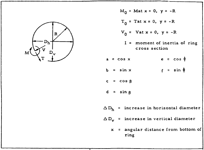
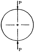
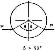
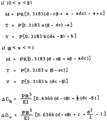
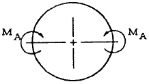
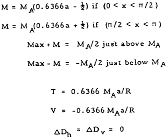
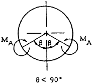
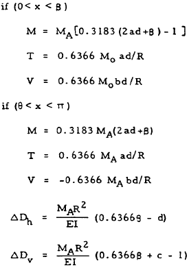
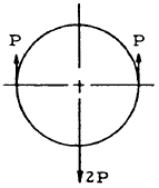
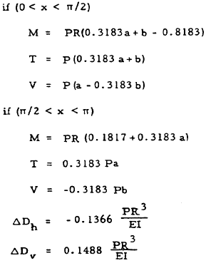
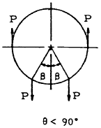
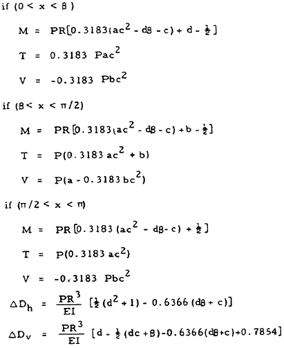
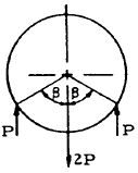
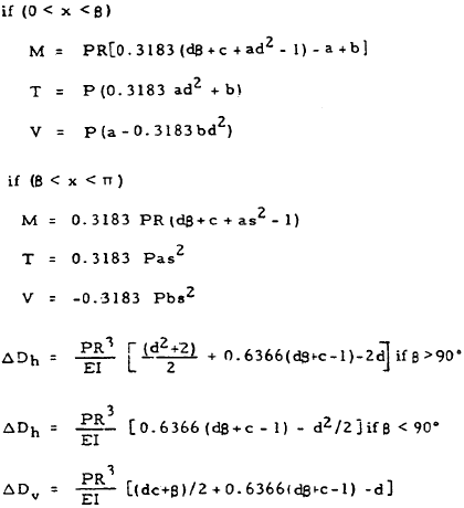
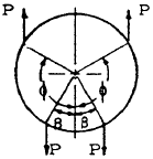
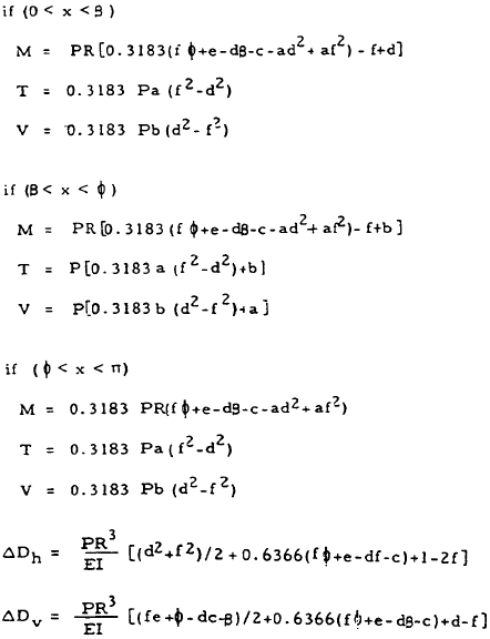
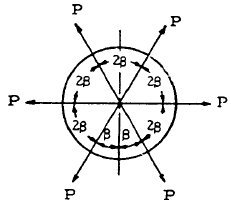
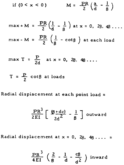
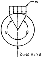
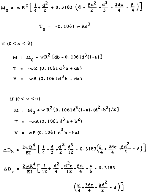
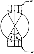
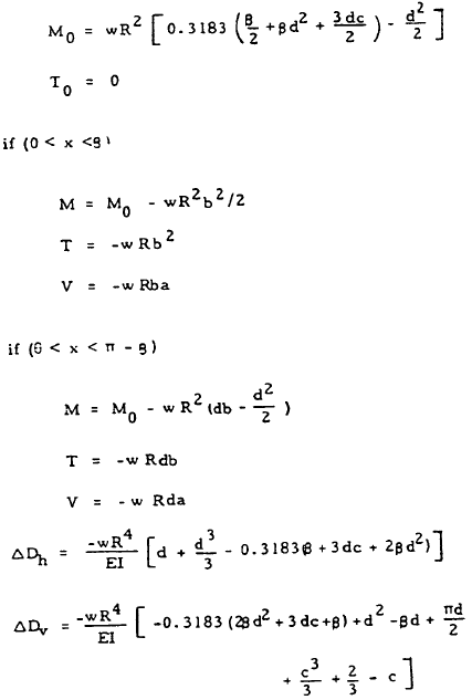
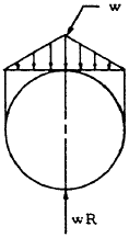
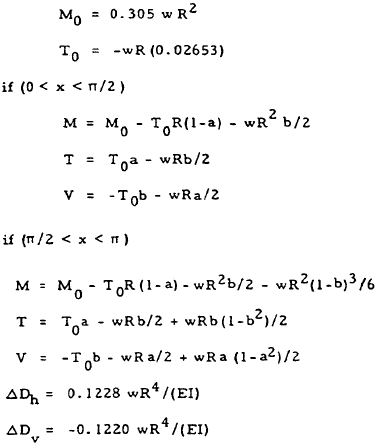
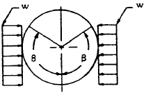
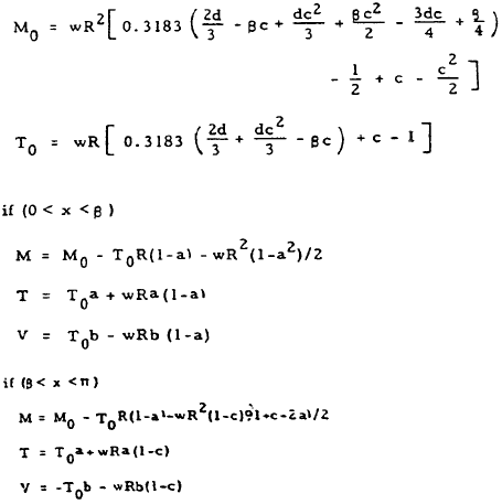
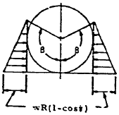
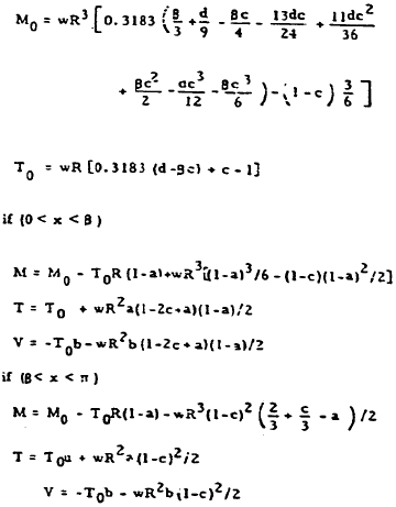
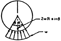
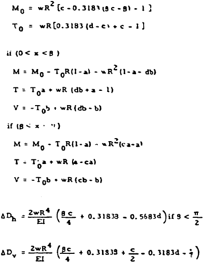
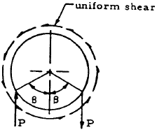
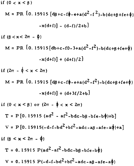
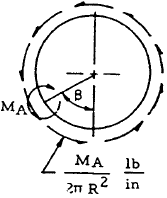
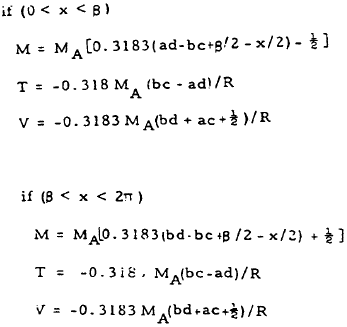
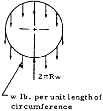
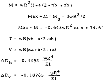
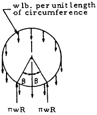
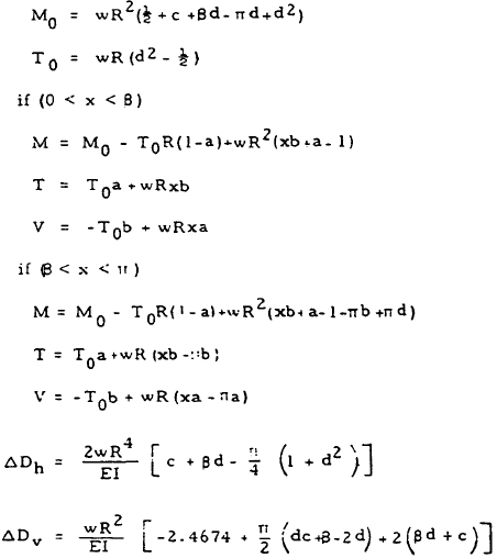
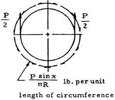
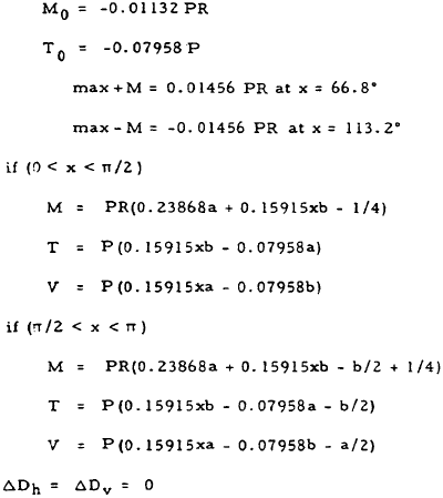
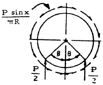
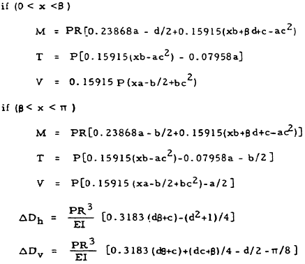
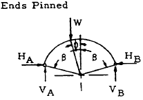
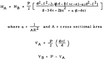
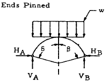
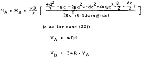
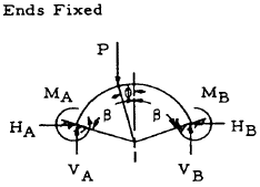
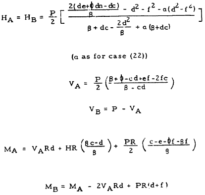
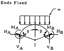
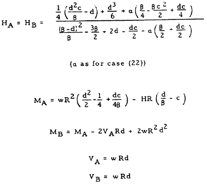
Table 5-6 gives formulas for the bending moments, tensions, shears, and deflections of closed circular rings and circular arches of uniform cross section loaded in various ways. Cases 1 through 21 treat closed rings, and cases 21 through 24 treat arches. By superposition, the formulas given by Table 5-6 can be combined to cover a wide variety of loading conditions.
These ring formulas are based on the following assumptions: (1) The ring is of such large radius in comparison with its radial thickness that the deflection theory for straight beams is applicable. (2) Its deflections are due solely to bending, the effect of direct axial tension or compression and that of shear being negligible. (3) It is nowhere stressed beyond the elastic limit. (4) It is not so severely deformed as to lose its essentially circular shape.
Since many of the formulas in Table 5-6 consist of a large number of terms, each of which may be large in comparison with the end result, calculations should be made with extreme care in order to ensure accurate results.
Table 5-6
Formulas for Closed Circular Rings of Uniform Cross Section
| Case | Illustration | Formulas |
|---|---|---|
| 1 |
|
|
| 2 |
|
|
| 3 |
|
|
| 4 |
|
|
| 5 |
|
|
| 6 |
|
|
| 7 |
|
|
| 8 |
|
|
| 9 |
|
|
| 10 |
|
|
| 11 |
|
|
| 12 |
|
|
| 13 |
|
|
| 14 |
|
|
| 15 |
|
|
| 16 |
|
|
| 17 |
|
|
| 18 |
|
|
| 19 |
|
|
| 20 |
|
|
| 21 |
|
|
| 22 |
|
|
| 23 |
|
|
| 24 |
|
|
| 25 |
|
|
We have a number of structural calculators to choose from. Here are just a few:
5.10 Sample Problem - Circular Rings and Arches
Given: The circular ring shown in Figure 5-18.
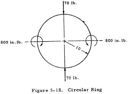
Find: The bending moments in the ring.
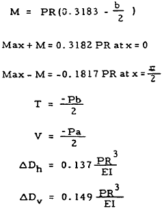
Solution: The bending moment in the ring may be obtained by superposing that due to the concentrated loads (Mp) and that due to the applied bending moments (Mm). From Table 5-6, case 1, the bending moment due to the concentrated loads is
From Table 5-6, case 3, the bending moment due to the applied moment is
or
The bending moment due to the combined loading is
$$ M = M_p + M_m $$Thus,
or
In the above expressions, x is the angular distance from the bottom of the ring.
