Bearing Stresses (Contact Stresses)
This page provides the chapter on bearing stress (also referred to as contact stress) from the "Stress Analysis Manual," Air Force Flight Dynamics Laboratory, October 1986.
11.1 Introduction to Bearing Stresses
The stresses developed when two elastic bodies are forced together are termed bearing stresses. They are localized on the surface of the material and may be very high due to the small areas in contact. The design information given in this section assumes either static loading or low velocity loading. The application to ball and roller antifriction bearings is not covered.
A brief discussion of bearing stresses in riveted joints is followed by a presentation of theoretically derived equations for the bearing stresses between various shapes in contact. An empirical treatment for the determination of allowable loads is also presented.
It is noted here that the design of ball and roller bearings is a very specialized area; however, their selections for various applications can be made based on data published by the various manufacturers.
11.2 Nomenclature for Bearing Stresses
| a | = | 1/2 the major diameter of an ellipse |
| c | = | 1/2 the minor diameter of an ellipse |
| D | = | diameter |
| E | = | modulus of elasticity |
| Fbr | = | allowable bearing load |
| Fcp | = | proportional limit in compression |
| Fcy | = | compressive yield stress |
| fbr | = | calculated bearing stress |
| fbrc | = | calculated compressive bearing stress |
| fbrs | = | calculated shear bearing stress |
| fbrt | = | calculated tensile bearing stress |
| K1, K2, K3 | = | coefficients in Table 11-1 |
| P | = | axial load |
| Pa | = | allowable axial load |
| R | = | minimum radius of curvature |
| R' | = | maximum radius of curvature |
| r | = | radius |
| r | = | cylindrical coordinate |
| t | = | thickness |
| t | = | width of rectangular area |
| w | = | load per length (lb/in) |
| wa | = | allowable load per length (lb/in) |
| x, y | = | rectangular coordinates |
| δ | = | deflection |
| θ | = | cylindrical coordinate |
| μ | = | Poisson's ratio |
| ϕ | = | angle shown in diagram for general case of two bodies in contact in Table 11-1 |
11.2 Bearing Stresses in Riveted Connections
Figure 11-1 shows a riveted connection between two plates.
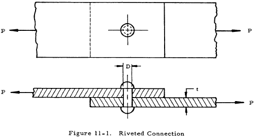
Excessive bearing stresses result in yielding of the plate, the rivet, or both.
The intensity of the bearing stress between the rivet and the hole is not constant but varies from zero at the edges to a maximum value directly in back of the rivet. The difficulty caused by considering a variable stress distribution may be avoided by the common practice of assuming the bearing stress to be uniformly distributed over the projected area of the rivet hole. The bearing stress is thus,
The allowable load is
where Fbr is the allowable bearing stress.
11.4 Sample Problem - Bearing Stresses in Riveted Connections
Given: The riveted plate in Figure 11-2
Find: The bearing stress between the rivets and the plate.
Solution: The load per rivet is 20,000/4 = 5,000 lb. From Equation (11-1),
$$ f_{br} = {P \over Dt} = {5,000 \over (0.5)(0.25)} = 40,000 ~\text{psi} $$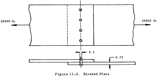
We have a number of structural calculators to choose from. Here are just a few:
11.5 Elastic Stresses and Deformation of Various Shapes in Contact
Table 11-1 treats the elastic stress and deformations produced by pressure between bodies of various forms. The first column of this table gives the form of the bodies and the dimensions that describe them. The second column indicates the shape and size of the surface of contact between the two bodies as well as the combined deformation of the bodies, δ. The maximum compressive, tensile, and shear bending stresses (fbrc, fbrt and fbrs) are given in the third column of Table 11-1. The maximum compressive and tensile bearing stresses occur at the center of the surface of contact and at the edge of the surface of contact, respectively, and the maximum shear bearing stress occurs in the interiors of the compressed parts. The equations in Table 11-1 are based on the assumption that the length of the cylinder and the dimensions of the plate are infinite. For a very short cylinder or for a plate having a width of less than five or six times that of the contact area or a thickness of less than five or six times the depth to the point of maximum shear stress, the actual stresses may vary considerably from those given by the equation in Table 11-1.
Because of the very small area involved in what initially approximates a point or line contact, the stresses obtained from the equations in Table 11-1 are high even for light loads. However, since the stress is highly localized and triaxial, the stress intensity may be very high (above the yield point) without producing apparent damage. Since this is the case and the formulas in Table 11-1 hold only in the elastic range, the empirical formulas for allowable loads given in Section 11.7 are most useful for practical design. However, the formulas in Table 11-1 are useful as a guide to design, especially when empirical formulas are not available for a given case.
| Form of Contacting Bodies | Shape of Contact Surface and Combined Deformation | Maximum Bearing Stress | |||||||||||||||||||||||||||||||||||||||||||||||||||||||||||||||||||
|---|---|---|---|---|---|---|---|---|---|---|---|---|---|---|---|---|---|---|---|---|---|---|---|---|---|---|---|---|---|---|---|---|---|---|---|---|---|---|---|---|---|---|---|---|---|---|---|---|---|---|---|---|---|---|---|---|---|---|---|---|---|---|---|---|---|---|---|---|---|
|
Sphere on Sphere 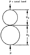
|

$$ r = 0.721 \sqrt[\uproot{1} \scriptstyle 3]{ P \left({D_1 D_2 \over D_1 + D_2}\right) \left[ {1 - \mu_1^2 \over E_1} + {1 - \mu_2^2 \over E_2} \right] } $$
$$ \delta = 1.04 \sqrt[\uproot{1} \scriptstyle 3]{ { P^2 (D_1 + D_2) \over D_1 D_2} \left( {1 - \mu_1^2 \over E_1} + {1 - \mu_2^2 \over E_2} \right)^2 } $$
|
$$ \text{Max}~ f_{brc} = 0.918 \sqrt[\uproot{1} \scriptstyle 3]{ P \left({ D_1 + D_2 \over D_1 D_2 }\right)^2 \over \left[ {1 - \mu_1^2 \over E_1} + {1 - \mu_2^2 \over E_2} \right]^2 } $$
If E1 = E2 = E and μ1 = μ2 = 0.3,
$$ \text{Max}~ f_{brt} = 0.0820 \sqrt[\uproot{1} \scriptstyle 3]{ P E^2 \left({ D_1 + D_2 \over D_1 D_2 }\right)^2 } $$
and
$$ \text{Max}~ f_{brs} = 0.205 \sqrt[\uproot{1} \scriptstyle 3]{ P E^2 \left({ D_1 + D_2 \over D_1 D_2 }\right)^2 } $$
|
|||||||||||||||||||||||||||||||||||||||||||||||||||||||||||||||||||
|
Sphere in Spherical Socket 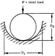
|

$$ r = 0.721 \sqrt[\uproot{1} \scriptstyle 3]{ P \left({D_1 D_2 \over D_1 - D_2}\right) \left[ {1 - \mu_1^2 \over E_1} + {1 - \mu_2^2 \over E_2} \right] } $$
$$ \delta = 1.04 \sqrt[\uproot{1} \scriptstyle 3]{ { P^2 (D_1 - D_2) \over D_1 D_2} \left( {1 - \mu_1^2 \over E_1} + {1 - \mu_2^2 \over E_2} \right)^2 } $$
|
$$ \text{Max}~ f_{brc} = 0.918 \sqrt[\uproot{1} \scriptstyle 3]{ P \left({ D_1 - D_2 \over D_1 D_2 }\right)^2 \over \left[ {1 - \mu_1^2 \over E_1} + {1 - \mu_2^2 \over E_2} \right]^2 } $$
If E1 = E2 = E and μ1 = μ2 = 0.3,
$$ \text{Max}~ f_{brt} = 0.0820 \sqrt[\uproot{1} \scriptstyle 3]{ P E^2 \left({ D_1 - D_2 \over D_1 D_2 }\right)^2 } $$
and
$$ \text{Max}~ f_{brs} = 0.205 \sqrt[\uproot{1} \scriptstyle 3]{ P E^2 \left({ D_1 - D_2 \over D_1 D_2 }\right)^2 } $$
|
|||||||||||||||||||||||||||||||||||||||||||||||||||||||||||||||||||
|
Sphere on Flat Plate 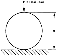
|

$$ r = 0.721 \sqrt[\uproot{1} \scriptstyle 3]{ P D \left[ {1 - \mu_1^2 \over E_1} + {1 - \mu_2^2 \over E_2} \right] } $$
|
$$ \text{Max}~ f_{brc} = 0.918 \sqrt[\uproot{1} \scriptstyle 3]{ P \over D^2 \left[ {1 - \mu_1^2 \over E_1} + {1 - \mu_2^2 \over E_2} \right]^2 } $$
If E1 = E2 = E and μ1 = μ2 = 0.3,
$$ \text{Max}~ f_{brt} = 0.0820 \sqrt[\uproot{1} \scriptstyle 3]{ P E^2 \over D^2 } $$
and
$$ \text{Max}~ f_{brs} = 0.205 \sqrt[\uproot{1} \scriptstyle 3]{ P E^2 \over D^2 } $$
at r/4 beneath the surface of the plate |
|||||||||||||||||||||||||||||||||||||||||||||||||||||||||||||||||||
|
Cylinder on Cylinder 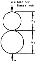
|

$$ b = 1.6 \sqrt{ {w D_1 D_2 \over D_1 + D_2} \left[ {1 - \mu_1^2 \over E_1} + {1 - \mu_2^2 \over E_2} \right] } $$
If E1 = E2 = E and μ1 = μ2 = 0.3,
$$ \delta = {2 (1 - \mu^2) w \over \pi E} \left( {2 \over 3} + \ln{2 D_1 \over b} + \ln{2 D_2 \over b} \right) $$
|
$$ \text{Max}~ f_{brc} = 0.798 \sqrt{ {w (D_1 + D_2) \over D_1 D_2} \over \left[ {1 - \mu_1^2 \over E_1} + {1 - \mu_2^2 \over E_2} \right] } $$
|
|||||||||||||||||||||||||||||||||||||||||||||||||||||||||||||||||||
|
Cylinder in Cylindrical Groove 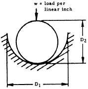
|

$$ b = 1.6 \sqrt{ {w D_1 D_2 \over D_1 - D_2} \left[ {1 - \mu_1^2 \over E_1} + {1 - \mu_2^2 \over E_2} \right] } $$
If E1 = E2 = E and μ1 = μ2 = 0.3,
$$ \delta = {2 (1 - \mu^2) w \over E} \left( 1 - 2 ~\ln{b \over 2} \right) $$
|
$$ \text{Max}~ f_{brc} = 0.798 \sqrt{ {w (D_1 - D_2) \over D_1 D_2} \over \left[ {1 - \mu_1^2 \over E_1} + {1 - \mu_2^2 \over E_2} \right] } $$
|
|||||||||||||||||||||||||||||||||||||||||||||||||||||||||||||||||||
|
Cylinder on Flat Plate 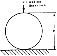
|

$$ b = 1.6 \sqrt{ w D \left[ {1 - \mu_1^2 \over E_1} + {1 - \mu_2^2 \over E_2} \right] } $$
If E1 = E2 = E and μ1 = μ2 = 0.3, the total compression of the cylinder between two plates is
$$ \Delta D = 4w \left({1 - \mu^2 \over \pi E}\right) \left( {1 \over 3} + \ln{2 D \over b} \right) $$
|
$$ \text{Max}~ f_{brc} = 0.798 \sqrt{ w \over D \left[ {1 - \mu_1^2 \over E_1} + {1 - \mu_2^2 \over E_2} \right] } $$
If E1 = E2 = 30×106 and μ1 = μ2 = 0.25,
$$ f_{brs} = 0.958 \sqrt{ w \over D } $$
at a depth of 0.393b below the surface of the plate. |
|||||||||||||||||||||||||||||||||||||||||||||||||||||||||||||||||||
|
Cylinder on Cylinder 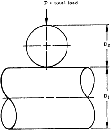
|

$$ a = K_1 \sqrt[\uproot{1} \scriptstyle 3]{ P \left({D_1 D_2 \over D_1 + D_2}\right) \left[ {1 - \mu_1^2 \over E_1} + {1 - \mu_2^2 \over E_2} \right] } $$
$$ b = K_2 c $$
$$ \delta = K_3 ~\sqrt[\uproot{1} \scriptstyle 3]{ { P^2 \over \left( {E_1 \over 1 - \mu_1^2} + {E_2 \over 1 - \mu_2^2} \right)^2 } { (D_1 + D_2) \over D_1 D_2 } } $$
where K1, K2 and K3 have values as follows:
|
$$ \text{Max}~ f_{brc} = {1.5 P \over \pi a b} $$
If E1 = E2 = 30×106, μ1 = μ2 = 0.25, and 1 < D1/D2 < 8,
$$ \text{Max}~ f_{brs} = {1175 ~O \over \left({D_1 \over D_2}\right)^{0.271} } ~\sqrt[\uproot{1} \scriptstyle 3]{ 4 P \over D_2^2 } $$
|
|||||||||||||||||||||||||||||||||||||||||||||||||||||||||||||||||||
|
General Case of Two Bodies in Contact 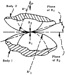
At point of contact, minimum and maximum radii of curvature are R1 and R'1 for Body 1 and R2 and R'2 for Body 2.
$$ \gamma = { 4 \over {1 \over R_1} + {1 \over R_2} + {1 \over R'_1} + {1 \over R'_2} } $$
$$ K = {8 \over 3} { E_1 E_2 \over E_2 (1 - \mu_1^2) + E_1 (1 - \mu_2^2) } $$
|
$$ \delta = K_3 ~\sqrt[\uproot{1} \scriptstyle 3]{ P^2 \over K^2 \gamma } $$ |
$$ \text{Max}~ f_{brc} = {1.5 P \over \pi a b} $$
where
$$ a = K_1 ~\sqrt[\uproot{1} \scriptstyle 3]{ P \gamma \over K } $$
and
$$ b = K_2 ~\sqrt[\uproot{1} \scriptstyle 3]{ P \gamma \over K } $$
|
|||||||||||||||||||||||||||||||||||||||||||||||||||||||||||||||||||
|
K1, K2 and K3 are given in the following table, where:
$$ \theta = \arccos{1 \over 4} ~\gamma ~\left[ \left({1 \over R_1} - {1 \over R'_1}\right)^2 + \left({1 \over R_2} - {1 \over R'_2}\right)^2 + 2 \left({1 \over R_1} - {1 \over R'_1}\right) \left({1 \over R_2} - {1 \over R'_2}\right) \cos{2 \phi} \right]^{1/2} $$
|
|||||||||||||||||||||||||||||||||||||||||||||||||||||||||||||||||||||
|
Knife Edge on Plate 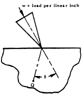
|
At any point Q,
$$ f_{brc} = { 2 w \cos{\theta} \over \pi r } $$
|
||||||||||||||||||||||||||||||||||||||||||||||||||||||||||||||||||||
|
Rigid Block on Plate 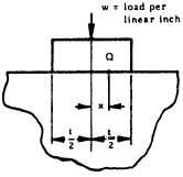
|
At any point Q on surface of contact,
$$ f_{brc} = { w \over \pi \sqrt{ {t^2 \over 4} - x^2 } } $$
|
||||||||||||||||||||||||||||||||||||||||||||||||||||||||||||||||||||
|
Rigid Cylindrical Die on Plate 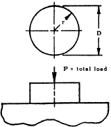
|
$$ \delta = { P (1 - \mu^2) \over D E } $$ |
At any point on surface of contact,
$$ f_{brc} = { P \over \pi D \sqrt{ {D^2 \over 4} - r^2 } } $$
\( \text{Max}~ f_{brc} = \infty \) at edge
|
|||||||||||||||||||||||||||||||||||||||||||||||||||||||||||||||||||
11.6 Sample Problem - Elastic Stress and Deformation of Cylinder on a Cylinder
Given: The cylinders shown in Figure 11-3.
Find: The contact surface, total deflection, and maximum compressive stress.
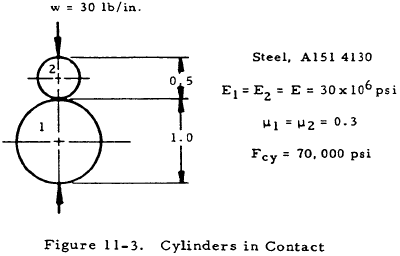
Solution: From Table 11-1, the surface of contact between two cylinders with their axes parallel is a rectangular strip of width, b, given by
$$ b = 1.6 \sqrt{ {w D_1 D_2 \over D_1 + D_2} \left[ {1 - \mu_1^2 \over E_1} + {1 - \mu_2^2 \over E_2} \right] } $$In this case,
The combined deflection of the cylinders is given by
$$ \delta = {2 (1 - \mu^2) w \over \pi E} \left( {2 \over 3} + \ln{2 D_1 \over b} + \ln{2 D_2 \over b} \right) $$if E1 = E2 = E and μ1 = μ2 = 0.3, which is true for the given cylinders. Thus, in this case,
From the third column of Table 11-1, the maximum compressive bearing stress between two parallel cylinders is
$$ \text{Max}~ f_{brc} = 0.798 \sqrt{ {w (D_1 + D_2) \over D_1 D_2} \over \left[ {1 - \mu_1^2 \over E_1} + {1 - \mu_2^2 \over E_2} \right] } $$In this case,
Thus, the cylinders will not yield and since Max fbrc < Fcy, the equations in Table 11-1 are valid.
We have a number of structural calculators to choose from. Here are just a few:
11.7 Empirical Treatment of Allowable Bearing Loads
Many tests have been made to determine the bearing strength of spheres and cylinders. However, it is difficult to interpret the results due to the lack of any satisfactory criterion for failure. Some permanent deformation is shown to be produced even for very small loads. This deformation increases progressively with increasing load, but there is no sharp break in the load-set curve. Thus, it is necessary to select some arbitrary criterion for the amount of plastic yielding that may be considered to represent failure. The circumstances of use determine the degree of permanent deflection necessary to make a part unfit for service.
The following sections present empirical formulas for the maximum allowable bearing loads for various shapes in contact.
11.7.1 Empirical Formulas for Allowable Bearing Loads of a Cylinder on a Flat Plate
Figure 11-4 shows a cylinder on a flat plate under a loading of w lb. per linear inch.
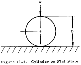
Table 11-2 gives empirical formulas for the allowable load (wa) for various diameters of steel cylinders on flat steel plates. It should be noted that there is little difference between failure under static conditions and that under slow rolling conditions if slipping does not occur. If slipping occurs, tests are necessary to obtain reliable information.
Although the allowable load (wa) is dependent upon length for short cylinders, it is independent of length if the cylinders are longer than 6 inches. The last equation in Table 11-2 is based upon an elongation of 0.001 in./in. in the bearing plate.
| Diameter | Loading Condition | Allowable Load (lb/in) |
|---|---|---|
| D < 25 in. | static |
$$ w_a = \left({ F_{cy} - 13000 \over 20000 }\right) 600 D $$
|
| 25 < D < 125 in. | static |
$$ w_a = \left({ F_{cy} - 13000 \over 20000 }\right) 3000 \sqrt{D} $$
|
| 116 < D < 476 in. | slow rolling |
$$ w_a = (18000 + 120 D) \left({ F_{cy} - 13000 \over 23000 }\right) $$
|
11.7.2 Empirical Formula for Allowable Bearing Load of Steel Spheres in Contact
Figure 11-5 shows two similar spheres in contact.
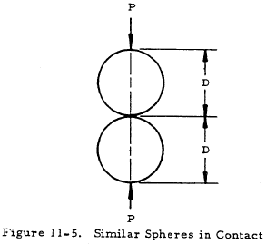
The crushing load P is given by
$$ P = 1960 (8D)^{1.75} $$The test sphere used to derive this formula was steel of hardness 64 to 66 Rockwell C.
