Cyclic Tensile Loading of Bars
This page provides the sections on bar analysis from the "Stress Analysis Manual," Air Force Flight Dynamics Laboratory, October 1986.
Other related chapters from the Air Force "Stress Analysis Manual" can be seen to the right.
- Bar Analysis
- Cyclic Tensile Loading of Bars
Introduction
Bars are thin structural members. This chapter gives procedures for determining the resistance to fatigue failure of bars under varying loads.
Nomenclature for Bar Fatigue Analysis
| A | = | cross-sectional area, in2 |
| ft | = | tensile stress, psi |
| fta | = | alternating stress, psi |
| ftm | = | mean stress, psi |
| Fty | = | yield stress in tension, psi |
| fse | = | endurance limit in torsion |
| K | = | stress concentration factor |
| Ke | = | effective stress concentration factor |
| Kt | = | theoretical stress concentration factor |
| n | = | factor of safety |
| P | = | load, lbs |
| Pa | = | alternating load, lbs |
| Pm | = | mean load, lbs |
| q | = | notch sensitivity factor |
3.5 Cyclic Tensile Loading of Bars
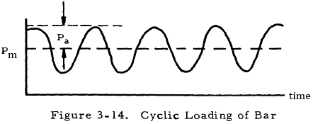
The case to be considered now is that for which an alternating axial load is applied to the bar. A diagram of this loading is shown in Figure 3-14. The mean load is designated as Pm, and the alternating component is designated as Pa.
For a brittle homogeneous material, a stress concentration factor must be applied to both the alternating and the mean stress in equations for failure under alternating loads since a static load is affected by stress concentration. Thus, the Soderberg relation becomes
where Sm and Sa are equal to Pm/A and Pa/A, respectively, and n is the factor of safety. In this case, Ke may be taken to be equal to Kt, so that the basic design equation becomes
where the A is either the reduced area at the discontinuity or the full area of the bar as given in Figures 3-1 through 3-12.
For a ductile material, a stress concentration factor need only be applied to the alternating stress in equations for failure since ductile materials under static loading have an effective stress concentration factor of one. In view of this, the Soderberg relation becomes
where ftm and fta are equal to Pm/A and Pa/A, respectively, and n is the factor of safety. Here, Am is the reduced area of the bar, and Aa may be either the reduced or the full area of the bar as given in Figures 3-1 through 3-12. Thus, the basic design equation for ductile rods under alternating tensile loads is
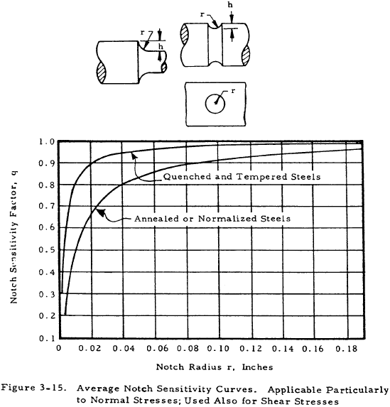
where Ke is equal to q (Kt − 1) + 1. Here, Kt is the theoretical stress concentration factor as obtained from Figures 3-1 through 3-12, and q may be obtained from Figure 3-15 for steel. For aluminum, magnesium and titanium alloys, fatigue data is scattered to the extent that a value of one is suggested for q.
Since cast iron is insensitive to stress raisers, stress concentration factors need not be applied in any formula governing alternatlng stresses. Thus, the Soderberg equation may be used in its basic form
where ftm and fta are equal to Pm/A and Pa/A, respectively, and A is the reduced area of the rod. Thus, the design equation for cast iron bars under an alternating tensile load becomes
The previous discussion of bars under alternating tensile loads is summarized in Table 3-2.
| Material Type | Design Equation | Explanation of Terms |
|---|---|---|
| ductile | $$ { 1 \over n } = { P_m \over A_m ~F_{ty} } + { K_e ~P_a \over A_a ~f_{se} } $$ | Am = reduced area of section. Ke = q (Kt − 1) + 1 where q is obtained from Figure 3-15 for steel or set equal to 1 for aluminum, magnesium, and titanium alloys, and where Kt is obtained from Figures 3-1 through 3-12. Aa = reduced or full area of section as given in Figures 3-1 through 3-12. |
| homogeneous brittle | $$ { 1 \over n } = { K_t ~P_m \over A ~F_{ty} } + { K_t ~P_a \over A ~f_{se} } $$ | Kt = theoretical stress concentration factor as obtained from Figures 3-1 through 3-12. A = reduced or full area of section as given by Figures 3-1 through 3-12. |
| cast iron | $$ { 1 \over n } = { P_m \over A ~F_{ty} } + { P_a \over A ~f_{se} } $$ | A = reduced area of section. |
We have a number of structural calculators to choose from. Here are just a few:
3.6 Sample Problem- Bar Under Cyclic Tensile Load
Given: A stepped circular bar with a fillet of 0.02 in. radius is to support a cyclic tensile load that is given as P = 20,000 lbs + 10,000 sinωt lbs. This bar, as shown in Figure 3-16, is made of an annealed steel for which Fty = 45,000 psi and fse = 35,000 psi. Use a factor of safety of 1.5.
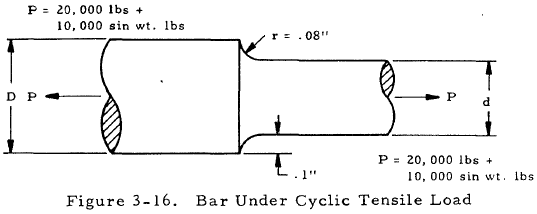
Find: The diameter d.
Solution: From Section 3.5, the basic design equation for a ductile material is
$$ { 1 \over n } = { P_m \over A_m ~F_{ty} } + { K_e ~P_a \over A_a ~f_{se} } $$Pm, Pa, and n are equal to 20,000 lbs, 10,000 lbs. and 1.5, respectively. By checking the explanation of terms in Section 3.5 and checking the figure referred to there, we find that both Aa and Am are the reduced area π d2/4. This explanation of terms also tells us that Ke = q (Kt − 1) + 1, where q is given by Figure 3-15. Consulting this figure, q = 0.89 and thus Ke = 0.89 (Kt − 1) + 1.
The above values may now be substituted into the basic equation to obtain
$$ { 1 \over 1.5 } = { 20000 \over {\pi d^2 \over 4} (45000) } + { [0.89 (K_t - 1) + 1] ~10000 \over {\pi d^2 \over 4} (35000) } $$Simplifying this equation gives
$$ 0.66 = { 0.605 + 0.323 K_t \over d^2 } $$Try d = 1.33. Since d/D and r/d are equal to 0.870 and 0.0601, respectively, Kt = 1.75 according to Figure 3-1. Substituting this in the above equation gives 0.6 = 0.6. Thus the guess for diameter is correct. If it were not, other diameters would have to be chosen to see if one satisfies the equation.
