MIL-HDBK-60: Threaded Fasteners - Tightening to Proper Tension
This page provides details on tightening threaded fasteners to the proper tension. This source of this page is MIL-HDBK-60, "Threaded Fasteners - Tightening to Proper Tension," 1990.
1. Scope
1.1 Scope. This document provides guidelines for the specification of proper bolt preloads and the selection of preload application methods. These guidelines may be used where no rules have been mandated either contractually or otherwise.
2. Applicable Documents
2.1 Government documents. Unless otherwise specified, the following specifications, standards and handbooks of the issue listed in the latest issue of the Department of Defense Index of Specifications and Standards (DoDISS) are applicable to this document to the extent noted herein.
| MILITARY SPECIFICATION | |
| MIL-S-8879 | Screw Threads, Controlled Radius Rmt with Increased Minor Diamter; General Specification for |
| FEDERAL STANDARD | |
| FED-STD-H28/1 | Screw-Thread Standards for Federal Services Section 1, Nomenclature, Definitions and Letter Symbols for Screw Threads |
| MILITARY HANDBOOK | |
| MIL-HDBK-5 | Metallic Materials and Elements for Aerospace Vehicle Structures |
(Unless otherwise indicated, copies of federal and military specifications, standards, and handbooks are available from the Naval Publications and Forms Center, ATTN: NPODS, 5801 Tabor Avenue, Philadelphia, PA 19120-5099.)
2.2 Other publications. None.
3. Definitions
3.1 Screw thread definitions and symbols follow FED-STD-H28/1. Definitions and symbols for metallic material physical properties follow MIL-HDBK-5. Specific symbols used are defined in the applicable sections of this document.
3.2 Metric measurement units are shown in parenthesis after their respective inch-pound measurement units.
3.3 The term "bolt" is used for bolts, screws and studs in this document.
4. General Information on Preloads
4.1 Preload for bolts in axial loaded joints. As a general rule, applied bolt preload should be sufficient to maintain joint members in contact and in compression. Loss of joint compression results in:
- Leakage of pressurized fluids past compression gaskets.
- Fastener loosening. Joint load cycles which open the joint, cause a loss in bolt tension. Thus, only a minimal preload may remain after a relatively small number of load applications.
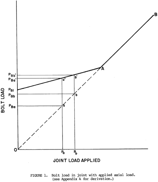
- Reduced fastener fatigue life. This may be understood by reference to figure 1. For a joint with no bolt preload, an axial load on the joint members is transmitted directly to the bolt so that the bolt load is equal to the joint load, or, in the case of multiple bolts, to a proportionate part of the joint load. This is shown in figure 1 as a straight line OAB. But when the bolt has a preload PB1 applied, axial joint load is partially absorbed by reduction of the compression in the joint members so bolt load increase is lower than in the non-preloaded joint. This is shown as line PB1A. Point A represents the separation of joint members with consequent loss of compression so further loading beyond point A is direct along line AB.
When an axial joint load varying between Pa and Pb is applied to a joint with no preload, bolt load varies between PBa and PBb. When preload PB1 has been applied, bolt load varies between PBa' an PBb'. As shown in figure 1, the latter condition results in a considerable reduction in cyclic load, hence, increased fatigue life. In some cases, preloading the joint bolts results in an increase in life from only a few hundred cycles before failure to an essentially unlimited fatigue life.
4.2 Preload for bolts in shear loaded joints. There are two basic types of shear joints. These are:
- Joint members slide. In this configuration, joint members transmit shear loads to the fasteners in the joint. Preload must be sufficient to hold the joint members in contact.
- Joint members do not slide. There is no relative motion between joint members. Shear loads are transmitted within the joint by frictional force. Preload must be sufficient to provide a normal force capable of providing a frictional force greater than the applied shear force.
NOTE: For high applied shear loads, shear stresses induced by preloading must be considered in the bolt design.
4.3 Preload for bolts in combined shear and axial loaded joints. Preload must be sufficient to perform functions noted in 4.1 and 4.2 above. Bolt loads must be analyzed to assure that bolts will not fail in either tension or shear using standard calculation procedures.
Need a Bolted Joint Calculator?
Try this bolted joint calculator.
- stress analysis of a bolted joint
- accounts for preload, applied axial load, and applied shear load
5. Preload Application
5.1 Preload application - general. In general, fasteners are designed for maximum utilization of material. Therefore, a maximum safe preload is normally applied. But, if, for standardization or logistic reasons, a lower strength bolt or nut is replaced by one of higher strength, preload values should not be increased. Preload should be based upon calculated joint requirements.
5.2 Preload below yield point. For joints subjected to cyclic loading and for joints using bolts of high strength materials, where yield strain is close to the strain at fracture, bolt loads are maintained below the yield point. Maximum bolt preloads specified are generally within the following ranges:
- 50 - 80% Minimum tensile ultimate strength
- 75 - 90% Minimum tensile yield strength or proof load
- 100% Observed proportional limit or onset of yield
5.3 Preload above yield point. For joints with primarily static loading using bolts of ductile material, where yield strain is relatively far from the strain at fracture, bolt preloads above yield are often used.
5.4 Preload limitation. Bolt head, driving recess (where used), and juncture of head and shank must be sufficiently strong to withstand the application of the selected preload. There must also be sufficient thread engagement to prevent stripping. Materials susceptable to stress corrosion cracking may require further preload limitation.
5.5 Preload adjustments.
5.5.1 Torsion load component. When preloads are applied directly (see 6.3) bolts are loaded axially. However, when preloads are applied by turning of nuts or bolts, a torsion load component is added to the desired axial bolt load. The combined loading increases the tensile stress on the bolt. This additional stress is often ignored by designers on the assumption that most of the torsional load quickly disipates soon after removing the driving force. While this may be true in joints tensioned near or beyond bolt yield, for critical joints where bolt tension must be maintained below yield it is important to adjust the axial tension load requirements to include the effects of preload torsion. For this adjustment, the combined tensile stress (also called "von Mises stress") may be calculated from the formula:
| where | ft = | Axial tensile stress applied in psi (MPa) |
| fs = | Shear stress caused by torsional load application in psi (MPa) |
The following formula has been derived from the above for single start Unified inch screw threads
$$ f_{tc} = f_t \sqrt{ 1 + 3 \left[ { 1.96 + 2.31 \mu \over 1 - {0.325P \over d_2} } - 1.96 \right]^2 } $$| where | μ = | Coefficient of friction in threads |
| n = | Number of threads per inch | |
| d2 = | Bolt thread pitch diameter in inches | |
| P = | Thread pitch in inches which equals 1/n |
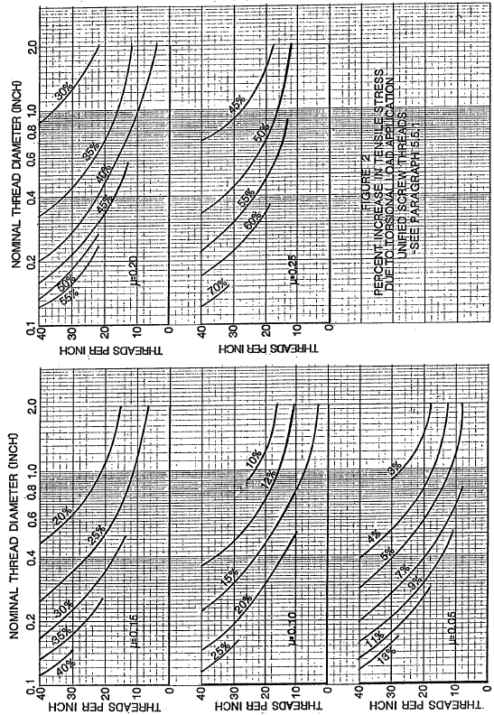
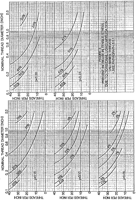
For Unified inch screw threads, the percent increase in tensile stress caused by preload torsion is plotted in figure 2 for a range of diameter-pitch combinations and friction coefficients. It is evident that tensile stress increase due to preload torsion becomes more significant when friction coefficient is higher and could result in bolt yield under preload stress unless allowance is made. For single start UNS screw threads in accordance with MIL-S-8879, with a thread stress diameter equal to bolt pitch diameter, the following formula applies
$$ f_{tc} = f_t \sqrt{ 1 + 3 \left[ {0.637P \over d_2} + 2.31 \mu \right]^2 } $$The percent increase in tensile stress caused by preload torsion is plotted in figure 3 for UNJ threads.
5.5.2 Preload relaxation. When preloads are first applied to bolts in a joint, local yielding takes place due to excess bearing stress under nut and bolt heads, local high spots, rough surface finish, and lack of perfect squareness of bolt and nut bearing surfaces. Also, loads are not distributed evenly on each thread in a joint. Thread deformation may, therefore, take place to redistribute load more evenly on the threaded parts. All this results in a loss of preload within a period of minutes to hours. As a general practice, an allowance for 10% loss of preload may be made when designing a joint. An alternative is to require retightening several minutes to several days after initial bolt load is applied. For critical joints, simulations may be used to determine the extent of preload loss and remedial actions required.
Increasing the resilience of a joint will make the joint more resistant to local yielding, i.e., there will be less loss of preload due to yielding. If practicable, a ratio of joint length to bolt diameter of 4 or greater is recommended. Use of through bolts, farside tapped holes, spacers and washers are design methods which can be used to increase this ratio.
Over a longer period of time, preload may be reduced or completely lost due to vibration, temperature cycling (including ambient temperature changes), creep, joint load, etc. An increase in joint bolt preload or, for transverse vibrations, use of a thread locking method which prevents relative motion within the joint, may solve preload relaxation problems caused by vibration and temperature cycling. Creep is generally a high temperature problem although some loss in bolt tension can be expected even at normal temperature. Harder materials and materials resistant to creep at the temperatures developed within the joint must be considered if creep is a problem. In any case, good joint design will minimize preload relaxation.
5.5.3 Preload uncertainty. Preload may be set with an inaccuracy of from a few percent to 25% or more. Care must be taken to maintain the calibration of torque and load indicators. Allowance should be made for uncertainties in bolt load to prevent overstressing of the bolts or insufficient preload. Select method for tensioning based upon required accuracy and relative costs (see section 6).
5.5.4 Temperature effects. For ambient temperatures outside the range of 30% to 200°F (-1°C to 93°C) allowance must be made for mechanical property differences from tabulated room temperature values. These properties include tensile strength, yield strength, modulus of elasticity, etc. Where bolts and flange materials are generically dissimilar, such as carbon steel and corrosion resistant steel or steel and brass, differences in thermal expansion may cause preload increase or decrease with temperature. Allowance must be made for these changes.
5.6 Back-turning following preload application.
5.6.1 By tightening bolts in a joint slightly beyond yield, the bolt and, in some cases, the joint materials, will be work hardened. Back-turning bolts or nuts to the desired bolt tension will reduce embedment and metal flow, to improve resistance to preload loss. Use would be mostly for soft, work-hardenable metals.
5.6.2 It was noted in 5.5.1 that preloads applied by turning a nut or bolt, add a torsional load component to the desired axial load. Some of this torsional load may be released immediately when the wrenching torque is released due to springback; the amount depends upon friction under the bolt head or nut. With controlled back-turning, the torsional load may be reduced or eliminated without loss of axial load. This reduces bolt stress which reduces creep and fatigue. Calculation and control of the back-turn angle are difficult so this method has limited use. Because of the small angles involved, it cannot be used for bolts which are relatively short.
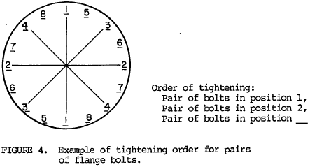
5.7 Flange joint bolt tensioning. It is important to apply approximately equal tension to each of the bolts in a flange joint, particularly if the joint includes a gasket. Unequal tension will result in leakage past the gasket. The recommended procedure is to tighten in stages, following a pattern of tightening a pair of opposite bolts, then a pair of opposite bolts 90° away, followed by pairs of opposite bolts in between. An example of the order of tightening pairs of bolts is shown in figure 4. After tightening fully, a retightening several hours later will help to assure preload relaxation will not cause the joint to leak. Following the above procedure is good practice even if a compressed gasket is not used for sealing.
Need a Bolted Joint Calculator?
Try this bolted joint calculator.
- stress analysis of a bolted joint
- accounts for preload, applied axial load, and applied shear load
6. Methods for Controlling Bolt Tension
6.1 Controlling bolt tension - general. The following are methods used for controlling initial bolt tension. There are other methods used which are not included however. Approximate preload accuracies and relative cost for some methods, which use manual load application, are listed in table I. Under the ideal conditions, bolt elongation control using an ultrasonic method can produce an accuracy as good as the strain gage method and at comparable cost. Tightening methods using power drive are similar in accuracy to equivalent manual methods, but equipment costs are higher.
NOTE: Regardless of tensioning method, tension may decrease with time if bolt/nut/washer seating surfaces deform under compressive load, if bolt stretches or creeps under tensile load, or if cyclic loading causes relative motion between the joint members.
| Preload Method | Load Accuracy | Relative Cost |
|---|---|---|
| Feel | ±35% | 1 |
| Torque wrench | ±25% | 1.5 |
| Turn of nut | ±15% | 3 |
| Preload indicating washer | ±10% | 7 |
Sensor wrench (computer controlled)
|
±15% ±8% |
8 8 |
| Bolt elongation | ±3-5% | 15 |
| Strain gages | ±1% | 20 |
6.2 Elongation measurement - stress below proportional limit.
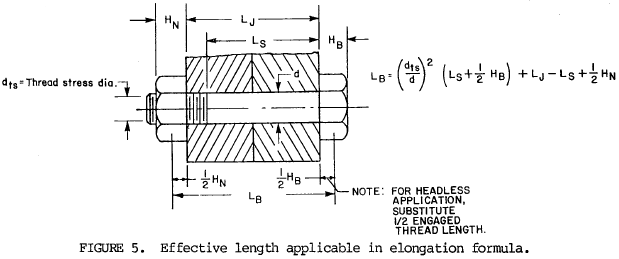
6.2.1 Micrometer method. Below the proportional limit, bolt elongation is directly proportional to axial stress, i.e., elongation increases in the same proportion as stress increases. If both ends of the bolt are accessible, a micrometer measurement may be made before and after tension is applied in order to insure proper axial stress. The following formula applies
| where | δB = | Bolt elongation in inches (mm) |
| ft = | Axial stress in psi (MPa) based upon thread stress area | |
| E = | Modulus of Elasticity in psi (GPa÷1000) | |
| LB = | Effective bolt length, see figure 5, in inches (mm) |
NOTE: For more complex bolt geometry, elongation is equal to the sum of the elongations of each section, with allowances made for transitional stresses in bolt head height and nut engagement length.
The micrometer method is most easily applied to a bolt that is threaded its entire length or has very few threads in the bolt grip area so that elongation will be practically uniform throughout the length. Ends must be parallel. It is not practical for general use but may be used on a limited basis.
6.2.2 Modified micrometer method. When both ends of a fastener are not accessible for measurement, if the diameter of the bolt or stud is sufficiently large, an axial hole may be drilled in it as shown in figure 6. By applying a micrometer depth gage to determine the change in depth of the hole during tightening of the fastener, the tension can be controlled as in 6.2.1.

6.2.3 Indicating bolt. This system consists of a bolt with a blind axial hole in which a pin is fixed at the bottom. The pin is usually made flush with the bolt head surface before loading. As the bolt is loaded, the elongation produced in the bolt causes the pin to move below the reference surface. This change in distance is converted directly into unit stress by measuring with a calibrated dial gage. In some cases, the pin is set a distance above the bolt head surface so that it is flush when the desired load is attained or a projection on the pin bears against the bolt head so that it cannot be turned by hand when the desired preload is reached. Another variation uses a dark colored fluid in the pin chamber. At tension zero, the bright colored end of the pin presses against the chamber window. As tension increases, the pin mves away from the window allowing an increasing amount of fluid to change the apparent color of the pin. A color sensor indicates load.
6.2.4 Turn-of-nut method. In principle, the turn-of-nut method is similar to that of the micrometer method described in 6.2.1 above, except that the lead of the thread is related to elongation. Thus
| where | θ = | Turn of nut in degrees |
| L = | Lead of the thread helix in inches (mm) |
so
$$ \theta = { 360 ~f_t ~L_b \over E ~L } $$Accuracy is affected by elastic deformation of the threads, by roughness of the bearing surfaces and by difficulty in determining the starting point for measuring the angle. Generally, the nut is tightened to seat the contacting surfaces firmly. The nut is then loosened to just release bolt tension and twisting; this is the starting point. Nut turn angle will be different for each bolt size, length, material and thread lead and will vary with the properties of the clamped materials. Unless the deformation of the nut and joint materials under load is negligible compared to that of the bolt, a significant portion of the nut rotation will be absorbed other than in elongation of the bolt. In such a case, the above formulas will not apply so nut turn angle would have to be determined empirically using a simulated joint and a tension measuring device as a standard.
6.2.5 Ultrasonic method. Sound pulse generated from one end of a bolt will travel at the speed of sound for the bolt material, to the other end of the bolt, bounce off that end and return to the generator in a certain period of time. This time is dependent upon the bolt length and the speed of sound; the speed of sound varies with material, temperature and stress level. An ultrasonic control system generates a pulse and measures the time for the pulse to travel the length of the bolt and return. Utilizing various inputs the system computes the stress, load or elongation of the bolt at any time by comparing pulse travel time in the loaded and unstressed conditions. To obtain consistent results, both ends of the bolt must be finished square to the bolt axis.
6.2.6 Strain gage method. When a thin wire is bonded to a bolt, it stretches as the bolt elongates under load. This stretch causes a change in electrical resistance of the wire which can be measured and correlated with bolt load. Strain gage wires or groups of wires may be bonded on the outside of the bolt or on the inside surface of a small axial hole where there is greater protection. Another method uses mounting in recesses on the outside of a plastic tube which is then bonded to the inside of a small axial hole in the bolt.
6.3 Direct loading.
6.3.1 Jacking methods. Application of axial load to a bolt may be made using mechanical jacking or jacking powered by air, hydraulic or explosive gas pressure. Often, loads are applied to bolt threads extending beyond the nut or to specially designed nuts which incorporate jacking screws or pistons. The elongation of the bolt creates a gap which is filled by turning the nut down snugly or by a shim, spacer or other mechanical device. Load is maintained after this jacking force has been removed.
6.3.2 Heating-temperature control. When a hot bolt and nut in a joint are cooled, the bolt shrinks and tension is developed. The following formula is used to calculate the temperature necessary to develop the required axial tensile stress in the bolt when the stress is below the elastic limit.
| Temperature, | $$ t = {f_t \over E e} + t_o $$ |
| where | ft = | Axial tensile stress, psi |
| E = | Modulus of elasticity, psi | |
| e = | Coefficient of linear thermal expansion /°F | |
| to = | Operating temperature, °F |
Example: A steel bolt operating at 70°F with an initial axial tensile stress of 40,000 psi. E = 30x106 psi and e = 6.2x10⁻⁶/°F.
$$ t = { 40,000 \over (30 \times 10^6) \times (6.2 \times 10^{-6}) } + 70 = 285 ^{\circ}\text{F} $$To provide bolt tension, the bolt and nut would be heated to a temperature slightly higher than the calculated temperature to allow for cooling prior to nut tightening. The nut would be tightened snugly and the assembly allowed to cool. Tension would develop during cooling. This method can only be used where the bolt is accessible for heating and where the heating will not degrade joint material. Accuracy is limited by the ability to control bolt temperature and by any significant deformation of the joint materials.
6.3.3 Heating - elongation control. Instead of using temperature controls to set bolt tension as described in 6.3.2, accuracy can be improved by using controlled expansion of the heated bolt. The joint would be seated snugly as in 6.2.4 and heat applied to the bolt. When the bolt expansion, as indicated by a thickness gage inserted under the nut, is equal to the elongation calculated as in 6.2.1 for the required axial stress, the nut would again be tightened snugly. Upon cooling, the axial expansion in the bolt should be approximately equal to the desired stress level. There will be some loss in preload if there is an appreciable increase in temperature of the joint materials during bolt heating.
6.4 Mechanical effect of load.
6.4.1 Washer or washer-face deformation.
- One device consists of two concentric steel rings sandwiched between two close-tolerance, hardened steel washers. The inner ring is smaller in diameter and higher than the outer ring by a predetermined amount. A known preload in the bolt is indicated when the inner ring is compressed and yielded, to the point indicated when the outer ring can no longer be moved freely by means of a pin inserted into one of the peripheral holes. Rotation of the fastener beyond the first indication of correct tension will result in a significant increase in resistance. Additional rotation could result in overtightening. Due to yielding of the inner ring, the washer assembly is not reusable.
- Other systems use calibrated deflection of a spring washer or deflection of projections on a washer or the bearing face of the fastener which flatten under axial load. The correct preload is indicated by checking the gap under the bolt head or nut using a feeler gage or spacer which may be an integral part of the joint.
- Still another type of system consists of a washer with either an integral tab or a separate member inserted into a radial groove on the fastener side of the washer. Under bolt preload, the tab or insert will deflect away from the joint to give an indication of the load.
6.4.2 Washer or hex fastener tab fracture.
- A variation of the washer tab or insert system described in 6.4.1c uses fracture of the exposed tab or insert when a predetermined fastener load is achieved.
- Another device consists of a tab adhesively bonded to the outer edge of a washer or to one of the vertical faces of a hex nut or bolt head. The bottom surface of the tab is flush with the bearing surface and transmits a shear load to the adhesive as the fastener is tensioned. It is designed to fracture at a predetermined fastener load.
6.4.3 Conical spring nut. Internally threaded conical springs retained in a drivable nut housing or cage will develop a predictable load when tightened. This is functionally similar to the use of spring washers described in 6.4.1b above.
6.4.4 Change in sonic velocity under stress. Using measured round trip transit times for longitudinal and shear wave sonic pulses, tensile stress in a bolt may be calculated without consideration of bolt length. This method permits checking bolt tension at any time without maintenance of records for each individual bolt in a joint at zero load. Accuracy is limited by sonic velocity variations between bolts of the same material and by corrections which must be made for the unstressed portions of the bolt head and threads. Both ends of the bolt must be finished square to the bolt axis.
6.5 Yield point tensioning. In order to utilize the maximum amount of bolt strength, bolts are sometimes tightened to or beyond the yield point of the material. Generally, this practice is limited to ductile materials where there is a considerable difference between the yield strength and the ultimate (breaking) strength. Materials of low ductility are more likely to fail, when preloaded to yield, due to unexpected overloads. Methods for tightening to yield range from the poorly controlled feel of the mechanic to the latest electronic equipment which compares torque applied to angle rotation to detect the change in the elastic properties of the material at yield. When tightening with automatic equipment, torque rate monitoring may also be used to detect yield point.
6.6 Torque control. The most common methods of bolt tension control are indirect since it is not usually practicable to measure tension produced in each fastener during assembly. Fortunately, for many applications the tension may be controlled within satisfactory limits by applying known torques in tightening the nuts on the bolts or studs, or tightening joint screws. Tests in numerous laboratories have shown that satisfactory torque-tension relationships may be established for a given set of conditions but that the change of any one variable may alter the relationship markedly. Because of the fact that most of the applied torque is absorbed in intermediate friction, a change in the surface roughness of the bearing surfaces or of the threads, or a change in lubrication will drastically affect the friction and thus the torque-tension relationship. Thus, it must be recognized that a given torque will not always produce the predicted stress in the bolt but will probably induce a stress that lies in a stress range that is satisfactory.
Note: Appendix B includes guidelines for the establishment of torque-tension relationships.
6.6.1 Torque wrench. A variety of torque wrenches are available. They are either manual or power driven using pneumatic, hydraulic or electric drive. Bolt tightening may be stopped when the desired torque is read on a dial or digital indicator, or when a buzzer sounds at a preset value. Some tools automatically disconnect the driving element at the desired torque setting or the driving element may break at a preselected torque.
6.6.2 Torque limiting fasteners. Some nuts, bolts and screws are available with special driving elements included. These driving elements are connected to the fasteners by controlled size sections designed to shear at specified torques. Thus, to apply the desired torque to a fastener, no special driving tool is required and problems of maintaining torque wrench accuracy are elminated.
6.7 Torque-tension comparison. Tension control based upon a calculated torque-tension relationship is subject to many variables. The less the number of variables, the greater will be the reliability of the joint. Therefore, the use of an actual or simulated joint with tension controlled by one of the methods in 6.2 and torque measured by a calibrated torque wrench, may be used to determine the torque to be applied in order to produce the required bolt tension. Another popular method utilizes a torque tension tester into which is placed the lubricated nut-bolt-washer unit to be used in a joint. As the nut is tightened, a piston applies pressure to hydraulic fluid in a chamber. The fluid pressure measurement is converted to show bolt tension. This system may be used to determine necessary torque to be applied or to set the shut-off of a power driven wrench. The first method better controls all the joint characteristics, but the tester method is satisfactory for most joint designs. Neither method eliminates the variations between joints, so bolt tension control is not as close as with methods which control tension directly. Friction force is the most significant variable.
Need a Bolted Joint Calculator?
Try this bolted joint calculator.
- stress analysis of a bolted joint
- accounts for preload, applied axial load, and applied shear load
Appendix A: Bolted Joint Behavior Under Applied Load
10. SCOPE
10.1 Scope. This appendix shows the derivation of a general formula describing behavior of a bolted joint subjected to an applied axial load. It is provided for information only.
10.2 Limitations. The following analysis covers only the condition where the axial load, P, applied to the joint, is applied over the same effective joint thickness, tj, which is subjected to the joint compression load, Pj. In many cases, the actual loading planes are within the joint, which leads to a complex loading situation. The condition covered below predicts somewhat higher bolt tensions prior to joint separation than exists when loading planes are within the joint material and joint separation occurring at a higher applied joint load. Eccentric loading on a joint causes joint separation at a lower load than axial loading and is not covered in the analysis.
20. APPLICABLE DOCUMENTS. This section is not applicable to this appendix.
30. DEFINITIONS
30.1 Definitions applicable to this appendix are in accordance with section 3.
30.2 The following symbols are used in this appendix
| AB | = | Effective bolt cross sectional area, in2 (mm2) |
| AG | = | Gasket area, in2 (mm2) |
| AJ | = | Effective compressed area in joint, in2 (mm2) |
| EB | = | Bolt modulus of elasticity, psi (MPa) |
| EG | = | Gasket modulus of elasticity, psi (MPa) |
| EJ | = | Joint material modulus of elasticity, psi (MPa) |
| LB | = | Effective bolt length, see figure 5, in. (mm) |
| tG | = | Gasket thickness, in. (mm) |
| tJ | = | Effective joint thickness, in. (mm) |
| P | = | Axial load applied to joint, pounds (Newtons) |
| PB | = | Axial bolt load, pounds (Newtons) |
| PG | = | Gasket compression load, pounds (Newtons) |
| PJ | = | Joint compression load, pounds (Newtons) |
| δB | = | Bolt elongation, in. (mm) |
| δG | = | Gasket compression, in. (mm) |
| δJ | = | Joint material compression, in. (mm) |
| Δ | = | Change caused by application of load P |
| T | = | Subscript indicating applicability to total joint including gasket |
| 1 | = | Subscript indicating condition with applied joint bolt preload only |
40. GENERAL STATEMENTS. This section is not applicable to this appendix.
50. THEORY
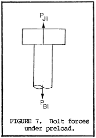
50.1 Preload application. When the bolts in a joint are tightened, the joint materials are compressed while the bolts are put in tension. The preload on a bolt, PB1, is equal to the compressive load on the joint material, PJ1 (see figure 7).
Stretch of a bolt under preload is
$$ \delta_{B1} = { P_{B1} L_{B} \over A_B E_B } $$Compression of the joint material under preload is
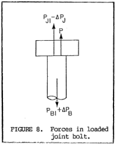
$$ \delta_{J1} = { P_{J1} t_{J} \over A_J E_J } $$50.2 Axial load applied - joint materials in compression. When an axial load, P, is applied to the joint, bolt stretch increases by ΔδB and bolt load increases by ΔPB. The increased bolt length reduces the compression in the joint materials by ΔδJ and the compressive loading by ΔPJ.
| $$ \Delta \delta_B = { \Delta P_B L_B \over A_B E_B } $$ | and | $$ \Delta P_B = { \Delta \delta_B A_B E_B \over L_B } $$ |
| $$ \Delta \delta_J = { \Delta P_J t_J \over A_J E_J } $$ | and | $$ \Delta P_J = { \Delta \delta_J A_J E_J \over t_J } $$ |
From figure 8, it is seen that
$$ P + P_{J1} - \Delta P_J = P_{B1} + \Delta P_B $$PB1 = PJ1 (See 50.1) and amount of additional bolt stretch equals the reduction in joint material compression, i.e., ΔδB = ΔδJ = Δδ. Using these relationships and substituting values for ΔPB and ΔPJ the following formula is derived.
| $$ \Delta P_B = { {A_B E_B \over L_B} \over {A_B E_B \over L_B} + {A_J E_J \over t_J} } P $$ | or | $$ { P \over 1 + { L_B A_J E_J \over t_J A_B E_B } } $$ |
and
$$ P_B = P_{B1} + \Delta P_B = P_{B1} + { P \over 1 + { L_B A_J E_J \over t_J A_B E_B } } $$50.3 Axial load applied - joint separated. When the applied axial load is sufficiently large to open the joint, there is no longer any load applied to the bolt by the joint materials. Therefore, as shown in figure 9, the applied load P is equal to the bolt load PB.
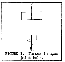
50.4 Joint separation. Referring to figure 1, line PB1A is the condition described in 50.2 and line AB is the condition described in 50.3. The point of joint separation, A, occurs when applied load is described by both conditions.
$$ P = { P_{B1} \over 1 - { 1 \over 1 + { L_B A_J E_J \over t_J A_B E_B } } } = P_{B1} \left( 1 + { t_J A_B E_B \over L_B A_J E_J } \right) $$50.5 Joints with gasket. When preload is applied, compression load on the gasket is the same as on the rest of the joint. Gasket compression is
$$ \delta_{G1} = { P_{G1} t_G \over A_G E_G } $$Total joint compression is
| $$ \begin{eqnarray} \delta_{JT1} &=& \delta_{J1} + \delta_{G1} \nonumber \\ &=& {P_{J1} t_J \over A_J E_J} + {P_{G1} t_G \over A_G E_G} \nonumber \\ &=& P_{B1} \left( {t_J \over A_J E_J} + {t_G \over A_G E_G} \right) \end{eqnarray} $$ | since PJ1 = PG1 = PB1 |
With axial load applied to the joint as in 50.2, compression in the total joint is reduced by ΔδJT and compression load is reduced by ΔPJT. Bolt loading is the same as in 50.2.
| $$ \Delta \delta_{JT} = \Delta P_{JT} \left( {t_J \over A_J E_J} + {t_G \over A_G E_G} \right) $$ | and |
| $$ \Delta P_{JT} = { \Delta \delta_{JT} \over {t_J \over A_J E_J} + {t_G \over A_G E_G} } $$ |
Applying the reasoning of 50.2
| $$ \Delta P_B = {P \over 1 + K} $$ | where | $$ K = { {L_B \over A_B E_B} \over {t_J \over A_J E_J} + {t_G \over A_G E_G} } $$ |
| and | $$ P_B = P_{B1} + \Delta P_B = P_{B1} + {P \over 1 + K} $$ |
Need a Bolted Joint Calculator?
Try this bolted joint calculator.
- stress analysis of a bolted joint
- accounts for preload, applied axial load, and applied shear load
Appendix B: Bolt Torque-Tension Relation
60. SCOPE
60.1 Scope. This appendix shows the derivations of a general formula and simplified formulas which relate bolt torque and axial tension developed. Examples are included.
60.2 Application. Information presented in this appendix is only one approach which may be used to determine bolt torque requirements. It is not mandatory and does not replace any existing design procedures.
70. APPLICABLE DOCUMENTS. This section is not applicable to this appendix.
80. DEFINITIONS
80.1 Definitions applicable to this appendix are in accordance with section 3.
80.2 The following symbols are used in this appendix:
| b | = | Washer face diameter, inch (mm) |
| d | = | Nominal diameter of bolt or nut, inch (mm) |
| d2 | = | Pitch diameter of bolt thread, inch (mm) |
| L | = | Lead of the thread helix, inch (mm) |
| PB | = | Axial bolt load, pounds (Newtons). This is equal to the stress area of the bolt threads multiplied by the stress level, in appropriate units. |
| PN | = | Normal load component of PB, pounds (Newtons) |
| T | = | Torque, pound-inch (Newton-mm) |
| α | = | Thread half angle, degrees |
| λ | = | Thread lead angle, degrees |
| μ | = | Coefficient of friction |
| π | = | 3.14159... |
90. GENERAL STATEMENTS. This section is not applicable to this appendix.
100. THEORY
100.1 Torque application. The purpose of torque application is to develop an axial load in the bolt. Torque required must also overcome friction in the threads and friction under the nut or bolt head.
100.2 Axial load torque. (Refer to figure 10). Axial load, PB, is a component of the normal force developed between threads. The normal force component perpendicular to the thread helix is PN λ. The other component of this force is the torque load, PB tanλ, which must be applied. Assuming the force is applied at the pitch diameter of the thread, torque to develop axial load is T1 = PB tanλ d2/2.
Since tanλ = L/πd2
$$ T_1 = { P_B L \over 2 \pi } $$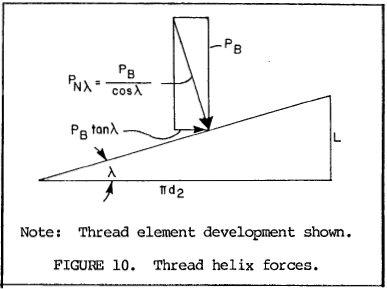
100.3 Thread friction torque. (Refer to figure 11). The normal force component perpendicular to the thread flanks is PN α. With a coefficient of friction, μ1, between the threads, the friction load is equal to μ1PNα, or μ1PB / cosα. Assuming the force is applied at the pitch diameter of the thread, torque to overcome thread friction is
$$ T_2 = { d_2 \mu_1 P_B \over 2 \cos{\alpha} } $$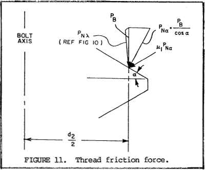
100.4 Nut or bolt underhead friction torque. (Refer to figure 12). With a coefficient of friction), μ2, between the nut or bolt head washer face and the joint, the friction load is equal to μ2PB. Assuming the force is applied midway between the nominal diameter, d, and the washer face diameter, b, torque to overcome nut or bolt underhead friction is
$$ T_3 = { (d + b) \over 4 } \mu_2 P_B $$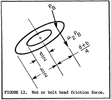
100.5 Torque-tension relation. Total torque, T, required to develop axial bolt load, PB, is equal to the sum of T1, T2 and T3 from 100.2, 100.3 and 100.4 above.
$$ T = P_B \left( {L \over 2 \pi} + {d_2 \mu_1 \over 2 \cos{\alpha}} + { (d + b) \mu_2 \over 4 } \right) $$100.5.1 For a fastener system with 60° threads, α = 30° and d2 is approximately 0.92d. If there is no loose washer used under the rotated nut or bolt head, b is approximately 1.5d.
$$ T = P_B \left[ 0.159 L + d \left( 0.531 \mu_1 + 0.625 \mu_2 \right) \right] $$100.5.2 If, in addition to conditions in 100.5.1, μ1 is approximately equal to μ2, then μ1 = μ2 = μ.
$$ T = P_B = \left( 0.159 L + 1.156 \mu d \right) $$Note: μ1 is not necessarily equal to μ2.
110. EXAMPLES
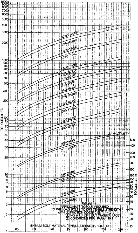
110.1 Values of torque, converted to pound-feet, were calculated for bolts preloaded to 55% of minimum tensile strength with coefficients of friction μ = 0.12 using conditions and formula from 100.5.2. These values are shown graphically in figure 13 for some common Unified coarse and fine threaded bolts at various strength levels. The difference in torques for coarse and fine threads is seen to be relatively small. Many references, therefore, use a simplified relation between torque and preload which excludes the thread lead effects.
NOTE: For UNJ threads in accordance with MIL-S-8879, tensile stress area is usually considered to be at the basic pitch diameter. Thus, the required tightening torque for a UNJ threaded bolt is larger than for an equally stressed Unified threaded bolt in an equivalent joint. To convert from the Unified to the UNJ, multiply the Unified threaded fastener torque by \( \left( {d_n - 0.6495 \over d_n - 0.9743} \right)^2 \) where d is basic major diameter and n is number of threads per inch.
110.2 Table II shows examples of coefficients of friction which are often used in determining torque requirements. So-called "dry" threads refer to threads where no lubricant is applied. Some residual machine oil is assumed. If all lubricant is removed by solvent, coefficient of friction is inconsistent and often very high unless plating or other film is acting as a lubricant. Severe galling may also result from lubricant-free surface conditions.
| Bolt/Nut Material (See Note) |
Lubricant | Coefficient of Friction, μ, ±20% |
|---|---|---|
| Steel | Graphite in Petrolatum or Oil | 0.07 |
| Steel | Molybdenum disulphide grease | 0.11 |
| Steel, Cadmium plated | None added | 0.12 |
| Steel, Zinc plated | None added | 0.17 |
| Steel | Machine oil | 0.15 |
| Steel/Bronze | None added | 0.15 |
| Corrosion resistant steel or nickel base alloys/silver plated materials | None added | 0.14 |
| Titanium/Steel | Graphite in petrolatum | 0.08 |
| Titanium | Molybdenum disulphide grease | 0.10 |
NOTE: "Steel" includes carbon and low alloy steels but not corrosion resistant steels.
110.3 For self-locking nuts, coefficient of friction for the mating materials and lubricants may be used in determining required torque. Prevailing torque, preferably measured, should be added to the torque calculated in this manner.
110.4 Figure 13 is an example only. A proper torque value should be determined for each joint individually.
