Fatigue Resistant Bolts
This page provides the sections on fatigue loading of bolted joints from Barrett, "Fastener Design Manual," NASA Reference Publication 1228, 1990.
Other related chapters from the NASA "Fastener Design Manual" can be seen to the right.
- Fastener Design Criteria
- Fastener Torque
- Loads on Fastener Groups
- Fatigue Resistant Bolts
- Rivets and Lockbolts
Fatigue-Resistant Bolts
If a bolt is cycled in tension, it will normally break near the end of the threaded portion because this is the area of maximum stress concentration. In order to lessen the stress concentration factor, the bolt shank can be machined down to the root diameter of the threads. Then it will survive tensile cyclic loading much longer than a standard bolt with the shank diameter equal to the thread outside diameter.
Fatigue (Cyclic) Loading of Bolts
The bolted joint in figure 26 (from ref. 1) is preloaded with an initial load Fi, which equals the clamping load Fc, before the external load Fe is applied. The equation (from ref. 3) for this assembly is
$$ F_b = F_i + \left({ K_b \over K_b + K_c }\right) F_e $$where Fb is the total bolt load. In this equation Kb is the spring constant of the bolt and Kc is the spring constant of the clamped faces. To see the effects of the relative spring constants, let R = Kc / Kb. Then (from ref. 2)
$$ F_b = F_i + \left({ 1 \over 1 + R }\right) F_e $$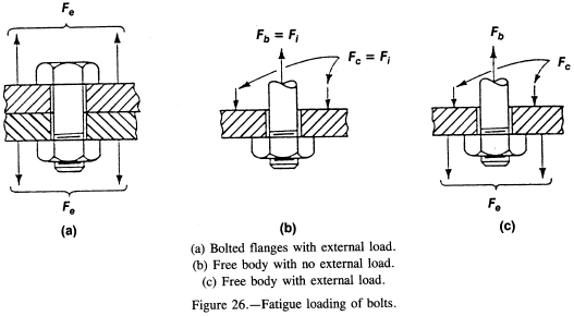
In a normal clamped joint Kc is much larger than Kb (R ≈ 5.0 for steel bolt and flanges), so that the bolt load does not increase much as the initial external load Fe is applied. (Note that the bolt load does not increase significantly until Fe exceeds Fi.)
In order to further clarify the effect of externally applied loads, a series of triangular diagrams (fig. 27, from ref. 11) can be used to illustrate loading conditions.
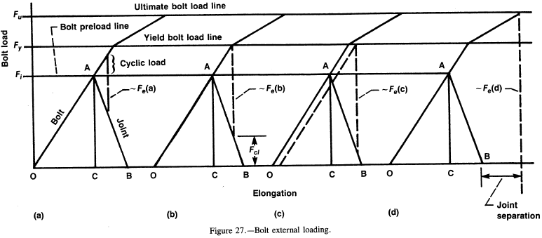
Triangle OAB is identical in all four diagrams. The slope of OA represents the bolt stiffness; the slope of AB represents the joint stiffness (joint is stiffer than bolt by ratio OC/CB.) In figure 27(a) the externally applied load Fe (a) does not load the bolt to its yield point. In figure 27 (b) the bolt is loaded by Fe (b) to its yield point, with the corresponding decrease in clamping load to FCL. In figure 27(c) external load Fe (c) has caused the bolt to take a permanent elongation such that the clamping force will be less than Fi when Fe (c) is removed. In figure 27(d) the joint has completely separated on its way to bolt failure.
Note that the flatter the slope of OA (or the larger the ratio OC/OB becomes), the smaller the effect Fe has on bolt load. Therefore, using more smaller-diameter fasteners rather than a few large-diameter fasteners will give a more fatigue-resistant joint.
Referring to figure 27(a), note that the cyclic (alternating) load is that portion above Fi. This is the alternating load (stress) to be used on a stress-versus-load-cycles diagram of the bolt material to predict the fatigue life of the bolts. Note that an initial preload Fi near the bolt yields minimizes cyclic loading.
Need a Bolted Joint Calculator?
Try this bolted joint calculator.
- stress analysis of a bolted joint
- accounts for preload, applied axial load, and applied shear load
Thermal Cyclic Loading of Bolts
If the bolt and joint are of different materials, an operating temperature higher or lower than the installation temperature can cause problems. Differential contraction can cause the joint to unload (or separate); differential expansion can cause overloading of the fasteners. In these cases it is common practice to use conical washers (see washer section of this manual) to give additional adjustments in fastener and joint loading.
References
- Bickford, J.H.: An Introduction to the Design and Behavior of Bolted Joints. Dekker, 1981.
- Juvinall, R.: Engineering Considerations of Stress, Strain, and Strength. McGraw-Hill, 1967.
- Donald, E.P.: A Practical Guide to Bolt Analysis. Mach. Des., vol. 53, Apr. 9, 1981, pp. 225-231.
