Plastic Yielding at Crack Tip
This page provides the chapter on plastic yielding at the tip of a crack from Wang, C. H. "Introduction to Fracture Mechanics," DSTO Aeronautical and Maritime Research Laboratory, DSTO-GD-0103, 1996.
Other related chapters from "Introduction to Fracture Mechanics" can be seen to the right.
3. Plastic Yielding at Crack Tip
In real materials, the theoretically very high elastic stresses in the vicinity of a crack tip exceed the yield strength of the materials. Consequently local plastic yielding will occur. Plastic yielding and the subsequent local elastic-plastic deformation at the tip of a crack plays an extremely important role in the fracture process of materials.
3.1 Irwin's Model
To determine the plastic zone at the crack tip, Irwin presented a simple model assuming the material is elastic-perfectly plastic. Consider the distribution of tensile stress σyy, acting across a line extending ahead of and in the same direction as the crack. The local y-stress near the crack tip is,
where r is the distance from the crack tip. As a first approximation, we can assume that the boundary between elastic and plastic behaviour occurs when the stress given by the above equation satisfies a yield criterion. For plane stress conditions, yielding occurs when σyy = σys, the uniaxial yield strength of the material. Then the distance ahead of the crack tip over which this happens is
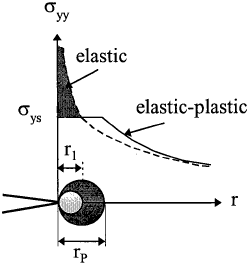
However, when yielding occurs, stresses must redistribute in order to satisfy equilibrium. Since when the elastic stress distribution within the plastic zone is replaced by a constant yield stress, the equilibrium condition along the y direction is violated. The cross-hatched region in Fig. 3.1 represents force that would be present in an elastic material but cannot be carried in the elastic-plastic material because the stress cannot exceed yield. The plastic zone must increase in size in order to accommodate these forces. A simple force balance leads to a second order estimation, assuming the force carried by the elastic stress distribution is the same before and after plastic yielding,
hence
Alternatively, the above result can also be obtained by considering a fictitious crack extending to the centre of the plastic zone, its tip centring at a + ½ rp, where rp is the size of the plastic zone yet to be determined. Stress distribution directly ahead of the crack is thus
Now we assume that the boundary between elastic and plastic regions is given by σyy = σys at x = rp/2, hence,
which is the same as equation (3.4). These results need to be modified for plane strain condition; see below.
Example 3.9 Determine the value of KI where the plane strain plastic zone engulfs the singularity dominated zone.
From Example 2.4 the size of the singularity zone is estimated to be equal to a/50. According to equation (3.4) we have
$$ {1 \over \pi} \left({K \over \sigma_{ys}}\right)^2 \le {a \over 50} $$or
$$ K \le 0.141 ~\sigma_{ys} \sqrt{\pi a} $$Therefore for a centre cracked plate, the applied stress has to be less than approximately 14.1% of the yield stress of the material; otherwise the stress intensity factor K would no longer provide a unique characterising parameter. Under plane strain condition, however, the applied stress can be higher, up to 35%. This will be discussed later.
Looking for Fracture Calculators?
Here are a few to choose from:
3.2 The Strip Yield Model
A different approach to finding the extent of the plastic zone was proposed by Dugdale and Barenblatt, who considered a long, slender plastic zone at the crack tip in a non-hardening material in plane stress. The strip yield plastic zone is modelled by assuming a crack of length 2a + 2ρ where ρ is the length of the plastic zone, with a closure stress equal to σys applied at each crack tip, see Fig.3.2. The size of ρ is chosen such that the stress singularity vanishes at the end of the effective crack:
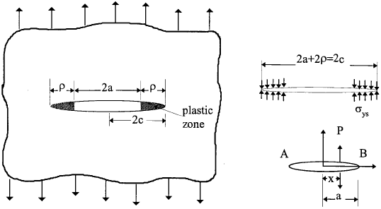
The stress intensity due to the closure stress can be estimated by considering a normal force P applied to the crack at a distance x from the centre line of the crack; the resultant stress intensity factors at the two crack tips are,
Here the closure force at a point within the strip yield zone is
thus the total stress intensity at each crack tip resulting from the closure stresses is obtained by replacing a with a + ρ = c and so
The stress intensity from the remote tensile stress, \( K_{\sigma} = \sigma \sqrt{\pi c} \), thereafter, equation (3.7) leads to
i.e.
Neglecting the higher order terms in the series development of the cosine, ρ is found
| $$ \rho = {\pi K^2 \over 8 \sigma_{ys}^2} $$ | $$ \left( {\sigma \over \sigma_{ys}} \ll 1.0 \right) $$ |
which is of the same order as equation (3.4) (the difference is about 23% ).
Looking for Fracture Calculators?
Here are a few to choose from:
3.3 Plane Stress versus Plane Strain
From Chapter 2, the triaxial stress state directly ahead of a crack tip is, σ1 = σ2 = σyy, σ3 = 0 for plane stress and σ3 = 2νσyy for plane strain. According to the Von Mises yield criterion, in terms of principal stresses,
where σys is the uniaxial yield stress. It can be easily shown that
For ν = 1/3 we have effective yield stress σy = 3σys. for plane strain. This means the plastic zone size under plane strain condition is approximately one ninth that under plane stress condition. In general, the effective yield stress can be expressed as,
where α is termed the plasticity constraint factor. From previous analysis, α = 1 for plane stress and α = 3 for plane strain. For a finite thickness plate, an empirical value often used is a = √3, that is,
Therefore the size of the plastic zone under plane strain condition is smaller than under plane stress condition by a factor of 1.732. In this case, the maximum applied stress level above which LEFM would become invalid is approximately three times higher, up to 35%.
Example 3.10 Determine the plastic zone length at fracture for a mild steel with KIC = 70 MPa√m and σys = 450 MPa for (a) plane stress and (b) finite thickness condition.
Solution Under plane stress condition,
$$ r_p = {1 \over \pi} \left({K_{1C} \over \sigma_{ys}}\right)^2 = {1 \over 3.14} \left({70 \over 450}\right)^2 = 7.7 \times 10^{-3} ~\text{m} $$and for finite thickness condition (taking a = √3),
3.4 Shapes of Plastic Zone
As the stress state ahead of a crack tip is three-dimensional, the shape of the plastic zone is not necessarily a circle, but needs to be determined using an appropriate yield criterion. Either the Tresca criterion or the Von Mises criterion is usually applied. Adopt the von Mises criterion given by equation (3.12), noting the crack tip stress distributions given by equations (2.29) and (2.30), the boundary of the plastic zone as a function of θ can be derived for plane stress condition and plane strain condition [σ3 = ν(σ1 + σ2)], respectively,
These two equations are plotted in Fig.3.3. Note that these are the first order estimates. Nevertheless, it indicates significant differences in the sizes and shapes of the mode I plastic zones for plane stress and plane strain conditions. The latter condition suppresses yielding, resulting in a smaller plastic zone for a given stress intensity factor. Similar equations can also be obtained for Mode II and Mode III.
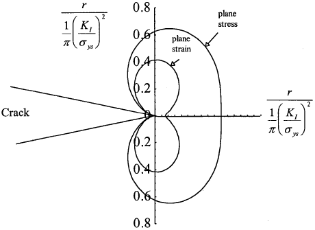
A modification similar to that outlined in section 3.1 can also be carried out to improve the above estimate; the second order estimate is just twice that given in equations (3.18) and (3.19), i.e.
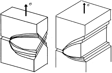
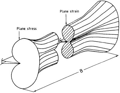
The three dimensional slip planes of a mode I crack are shown in Fig.3.4 for plane stress and plane strain. For a finite plate, due the free surface effect, the plastic zone looks like a "dog-bone", as depicted in Fig.3.4. Due to this thickness effect, the plastic constraint factor normally lies between 1 and 3, for example α = 1.7. It is important to point out that although the plastic zone at the middle of the plate is smaller than that near the surface, the high triaxial stress that exists at the middle of the plate (this is sometimes called plastic constraint) causes crack growth to occur there first, under both static and fatigue conditions.
Looking for Fracture Calculators?
Here are a few to choose from:
3.5 Crack Tip Opening Displacement
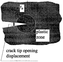
Due to plastic deformation at crack tip, the originally point sharp crack tip would become blunt (otherwise stress singularity will exist), resulting in a finite radius at the tip of the initial crack. This phenomenon is normally called crack tip opening, as if the tip of the crack opens up. One simple way of estimating this radius is through the fictitious crack method discussed in section 3.1. Since the fictitious crack tip is at a distance rp/2 ahead of the initial crack tip, a finite gap now exists between the faces of the fictitious crack at the tip of the initial crack, as depicted in Fig.3.6, which is equal to
where E' and σy are the effective Young's modulus and yield stress, respectively, which are defined by equations (1.8) and (3.16) for plane stress and plane strain. This is shown in Fig.3.7.
A similar estimate can be obtained from the strip yield model, although the calculations are slightly more involved. Here only the final result is given,
which is about 27 per cent lower than the Irwin model prediction Again E' and σy for plane strain condition are as defined previously. The fact that the crack tip would attain a finite radius due to plastic deformation makes the distinction between notch and crack even more blurry. But it is important to note that the crack tip opening displacement is stress dependent, unlike notch root radius.
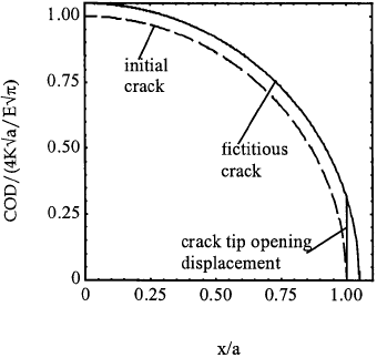
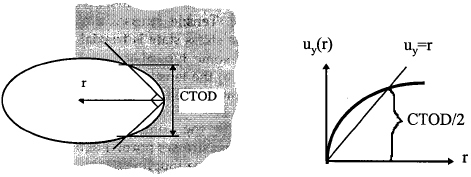
However, the definition of crack tip opening displacement in general is not so straightforward, as the relative displacement between the upper and lower crack faces at the very tip of the crack is mathematically zero. A more general, alternative definition is given by Rice (1968): crack tip opening displacement is defined as the opening where 45° lines emanating back from the crack tip intercept the crack faces, as depicted in Fig.3.8. Often the crack opening profile behind the crack tip is plotted versus the distance from the crack tip, and then the height at the intersection between the crack opening curve and line uy = r is defined as the crack tip opening displacement.
