Fracture Mechanics Fundamentals
This page provides the chapter on fracture mechanics fundamentals from Wang, C. H. "Introduction to Fracture Mechanics," DSTO Aeronautical and Maritime Research Laboratory, DSTO-GD-0103, 1996.
Other related chapters from "Introduction to Fracture Mechanics" can be seen to the right.
1. Fundamentals
1.1 Historical Overview
All engineering components and structures contain geometrical discontinuities - threaded connections, windows in aircraft fuselages, keyways in shafts, teeth of gear wheels, etc. The size and shape of these features are important since they determine the strength of the artefact. Conventionally, the strength of components or structures containing defects is assessed by evaluating the stress concentration caused by the discontinuity features. However, such a conventional approach would give erroneous answers if the geometrical discontinuity features have very sharp radii. To illustrate this point, consider the following four cases:
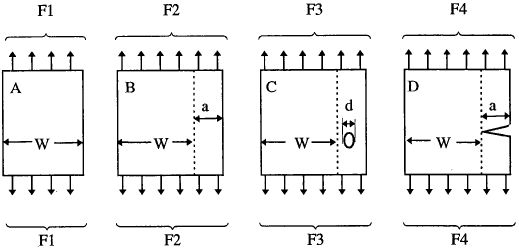
The thickness of each plate is the same. The forces required to break the four samples can be arranged in the following order:
Clearly the sizes of the defects at F3 and F4 are crucial to the strength of the structure.
Fracture mechanics is a set of theories describing the behaviour of solids or structures with geometrical discontinuity at the scale of the structure. The discontinuity features may be in the form of line discontinuities in two-dimensional media (such as plates, and shells) and surface discontinuities in three-dimensional media. Fracture mechanics has now evolved into a mature discipline of science and engineering and has dramatically changed our understanding of the behaviour of engineering materials. One of the important impacts of fracture mechanics is the establishment of a new design philosophy: damage tolerance design methodology, which has now become the industry standard in aircraft design.
"Fracture mechanics" is the name coined for the study which combines the mechanics of cracked bodies and mechanical properties. As indicated by its name, fracture mechanics deals with fracture phenomena and events. The establishment of fracture mechanics is closely related to some well known diasters in recent history. Several hundred liberty ships fractured extensively during World War II. The failures occurred primarily because of the change from riveted to welded construction and the major factor was the combination of poor weld properties with stress concentrations, and poor choice of brittle materials in the construction. Of the roughly 2700 liberty ships built during World War II, approximately 400 sustained serious fracture, and some broke completely in two. The Comet accidents in 1954 sparked an extensive investigation of the causes, leading to significant progress in the understanding of fracture and fatigue. In July 1962 the Kings Bridge, Melbourne failed as a loaded vehicle of 45 tonnes crossing one of the spans caused it to collapse suddenly. Four girders collapsed and the fracture extended completely through the lower flange of the girder, up the web and in some cases through the upper flange. Remarkably no one was hurt in the accident.
Fracture mechanics can be divided into linear elastic fracture mechanics (LEFM) and elasto-plastic fracture mechanics (EPFM). LEFM gives excellent results for brittle-elastic materials like high-strength steel, glass, ice, concrete, and so on. However, for ductile materials like low-carbon steel, stainless steel, certain aluminium alloys and polymers, plasticity will always precede fracture. Nonetheless, when the load is low enough, linear fracture mechanics continues to provide a good approximation to the physical reality. The purpose of this lecture is to provide a broad picture of the theoretical background to fracture mechanics via a stress analysis view point.
Looking for Fracture Calculators?
Here are a few to choose from:
1.2 Notches and Stress Concentration
There seems to be confusion among many engineers between notches and cracks. This is not surprising as the boundary between notch and crack is sometimes blurred, especially under fatigue conditions.
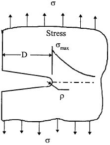
A notch is defined as geometric discontinuity which has a definite depth and root radius. Examples are bolt holes, screw threads or oil holes. The effect of a notch on a tensile stress field is easily visualised by the familiar "stress flow" analogy which illustrates the high "density" of stress around the root of a notch, Fig.2. This analogy is very useful in deciding upon an apparently contradictory course of action: removing or adding material to smooth out the flow of stress, hence making component stronger. For instance, if we remove the material (width = a) in Fig.1, we can recover the loss of strength in cases C and D to the same level as in case A.
The stress concentration factor, KT, which reflects the severity of a notch, is defined as the dimensionless ratio of the maximum (elastic) stress at the root of a notch, to the nominal applied stress. The suffix T derives historically from theoretical elasticity theory. The stress concentration factor can be evaluated using analytical, numerical and experimental techniques; for common notch shapes the KT values can also be obtained from a wealth of tables and charts. One practical approximation for many notch shapes is the formula for elliptical notch shapes:
where D and ρ are the notch depth (or half notch diameter) and the notch root radius, respectively. The KT value for a circular hole is equal to 3, hence relatively shallow notches can cause local notch root stress to rise above the material's strength even for modest values of nominal applied stress. Therefore the presence of a notch can be crucial to the safety of components made of brittle materials. It should be noted that the local maximum stress at failure for a notched component is not strictly constant but may vary with the notch depth. For ductile materials, notches are less dangerous, since the stress gradient ahead of a concentrating feature is steep thus limiting the spread of plasticity to a small region and avoiding plastic collapse. However, this saving grace for static loading can become, and probably is, the greatest single cause of failures in operating plant subjected to repeated loading. This is because fatigue cracks can be initiated in the plastic zone of a notch and become very sharp stress concentrating features (better known as cracks) in their own right, able to propagate under the lower stress level existing within the bulk of the material.
1.3 Cracks and Stress Intensity Factor
From equation (1.1) we can see if we reduce the notch root radius, ρ, to a very small value, even approaching a mathematical zero (in engineering terms, to the order of the dimensions of an atom, 10-9m), the stress concentration factor KT tends to approach infinity; the geometry is reduced to a crack. As a result, the crack tip stress approaches a theoretical value of infinity, irrespective of notch depth,
Clearly the idea of stress concentration factor breaks down for a crack, since it cannot distinguish between various crack lengths and applied stress levels.
It is interesting, however, to examine a product,
which remains finite and contains the information of remote applied load and the size of the crack. All we will see later, this new parameter is the so called "stress intensity factor".
Looking for Fracture Calculators?
Here are a few to choose from:
1.4 Plane Stress and Plane Strain
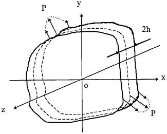
Plane stress: a thin plate loaded with forces parallel to its plane and distributed symmetrically over the whole thickness. Stress components σz, τzx, τzy are zero and there are only three nonzero stress components: σx, σy, τxy. The stress and strain tensors can be written as,
| Stress tensor: | $$ \left| \begin{array}{ccc} \sigma_x & \tau_{xy} & 0 \\ \tau_{xy} & \sigma_y & 0 \\ 0 & 0 & 0 \\ \end{array} \right| $$ |
| Strain tensor: | $$ \left| \begin{array}{ccc} \varepsilon_x & \gamma_{xy} & 0 \\ \gamma_{xy} & \varepsilon_y & 0 \\ 0 & 0 & \varepsilon_z \\ \end{array} \right| $$ |
where \( \varepsilon_z = - {\nu \over E} (\sigma_x + \sigma_y) \)
and Hooke's law is
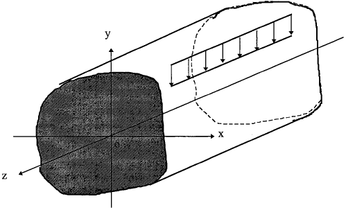
Plane strain: A long cylindrical or prismatical body subjected to forces that are normal to its axis and do not vary along the length. There are three non-zero strain components (εx, εy, γxy), as εz = γxz = γyz = 0. The stress and strain tensors are,
| Stress tensor: | $$ \left| \begin{array}{ccc} \sigma_x & \tau_{xy} & 0 \\ \tau_{xy} & \sigma_y & 0 \\ 0 & 0 & \sigma_z \\ \end{array} \right| $$ |
where σz = ν (σx + σy )
| Strain tensor: | $$ \left| \begin{array}{ccc} \varepsilon_x & \gamma_{xy} & 0 \\ \gamma_{xy} & \varepsilon_y & 0 \\ 0 & 0 & 0 \\ \end{array} \right| $$ |
The above Hooke's law for plane stress condition are also applicable if we make the following formal changes to it: substitute constants
| ν by | $$ \nu' = {\nu \over 1 - \nu} $$ |
| E by | $$ E' = {E \over 1 - \nu^2} $$ |
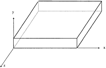
There seems to be quite a lot of confusion about plane strain or plane stress. Consider a plate as shown in Fig.1.5: it is a plane stress problem if the plate is subjected to in-plane loading and the interest is about the stresses and deformation in the xz plane, otherwise it should be treated as plane strain for both the xy and zy planes. A rule of thumb is that if the dimension normal to the plane of interest is much greater than the in-plane dimensions, then it is plane strain, otherwise plane stress. Furthermore, the concept of plane stress or plane strain is mainly for the convenience of 2D representation of actual 3D structure, hence it is relative. In many cases the determining factor is whether there exists a high stress/strain gradient near the point of interest. For example, if the plate shown in Fig.1.5 is subjected to bending in the xy or zy plane, it should be considered as plane strain state and the effective Young's modulus should be E / (1 - ν 2). This is because the high strain gradient through the plate thickness induced due to Poisson's ratio effect cannot be fully developed.
Looking for Fracture Calculators?
Here are a few to choose from:
1.5 Stress Function
From the theory of elasticity it is easy to show that a true solution to a two dimensional problem must satisfy (i) equilibrium, (ii) compatibility, (iii) boundary conditions. The equations of elasticity reduce to two-dimensional forms in three special cases, as discussed previously:
- Plane Strain: In this case the displacement component uz, is identically equal to zero, and none of the physical quantities depends on z.
- Plane Stress: In a state of plane stress parallel to the xy-plane, the stress components σxz, σyz and σzz all vanish but the components of the displacement vector are not independent of z.
- Generalised Plane Stress: This is a state of stress in a thin plate −h ≤ z ≤ h when σzz = 0 throughout the plate but σxz = σyz = 0 only on the surfaces z = ±h of the plate.
For 2D problems, the first two requirements can be automatically satisfied by choosing an Airy stress function, Φ (see Timoshenko, 1970) such that,
| $$ \sigma_x = {\partial^2 \Phi \over \partial y^2} $$ | $$ \sigma_y = {\partial^2 \Phi \over \partial x^2} $$ | $$ \tau_{xy} = {\partial^2 \Phi \over \partial x \partial y} $$ |
where the stress function is bi-harmonic,
Thus the solution of a two-dimensional problem, when the weight of the body is only body force, reduces to finding a solution of equation (1.10) that satisfies the boundary conditions of the problem.
A major development in the field of two-dimensional elasticity has been Muskhelishvili's (1953) work on the complex form of the two-dimensional equations. Before we proceed, however, it is necessary to review some fundamental concepts in complex analytic functions. For an analytic function f(z), where z = x + iy, we have
| $$ {\partial \over \partial x} f(z) = f'(z) $$ | and | $$ {\partial \over \partial y} = i f'(z) $$ |
from which it is easy to show the Cauchy-Riemann conditions (Note 1). Now let us define
where K = 3 − 4ν for plane strain and K = (3 − ν)/(1 + ν) for plane stress. Here the complex variable is z = x + iy, referring to a generic point in the xy plane. Note z = x − iy. Functions ϕ and χ are arbitrary complex potentials. The transformation of the Muskhelishvili formulas using a conformal mapping method from the z-plane to a ζ-plane (where z = x + iy and ζ = ξ + iγ) is of great use in discussing boundary value problems. For further details please see Ref (Muskhelishvili, 1953).
Two special cases of the formulas (1.11) are associated with the name of Westergaard (1939). If we make the substitutions,
| $$ \phi'(z) = {1 \over 2} Z(z) $$ | $$ \chi'(z) = -{1 \over 2} z Z'(z) $$ |
where function Z is an analytic function of the complex variable z. It is easy to show that the following function satisfies equation (1.10), noting the Cauchy-Riemann conditions for the differentiation of an analytic complex variable,
where Z = ∫Zdz and Z = ∫ Z dz. Now equations (1.11) reduce to
It should be observed that this solution has the property that, on the line y = 0, σxy = 0 and σxx = σyy. When a conformal mapping is performed, this boundary condition represents a plate with a hole subjected to a hydrostatic pressure, for which the stress solution is known.
Similarly, if we make the substitutions
| $$ \phi'(z) = {1 \over 2} i Z_2(z) $$ | $$ \chi'(z) = -{1 \over 2} i z Z_2'(z) + i Z_2(z) $$ |
we find the corresponding stress field is given by
This solution has the property that, on the line y = 0, σyy = 0.
For illustration purposes, let us consider a case of an unstressed elliptic hole in an infinite plate that is subjected to "all-round" tension. The problem can be solved by using the following simple conformal mapping of the exterior of an ellipse into the interior of a unit circle, for which the stresses are known,
where z = x + iy and ζ = ξ + iγ. That is x = c coshξ cosγ and y = c sinhξ sinγ, representing a curvilinear coordinate system in which the elliptic boundary is defined by ξ = α. Detailed solutions for this problem can be found in Ref.(Timoshenko,1970).
Footnotes
Note 1: Cauchy-Riemann conditions:
| so | $$ \nabla^2 \text{Re} Z = \nabla^2 \text{Im} Z = 0 $$ |
