Stress Intensity Factor
This page provides the sections on the stress intensity factor from Wang, C. H. "Introduction to Fracture Mechanics," DSTO Aeronautical and Maritime Research Laboratory, DSTO-GD-0103, 1996.
Other related chapters from "Introduction to Fracture Mechanics" can be seen to the right.
2.4 Stress Intensity Factor K
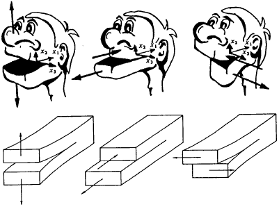
Before proceeding to consider the stress analysis of cracked bodies, it is important to distinguish basic "modes" of stressing. As shown in Fig.2.9, the three basic modes are: opening (mode I), in-plane shear (mode II) and out-of-plane tearing (mode III). Mode I corresponds to normal separation of the crack faces under the action of tensile stresses, which is by far the most widely encountered in practice. The difference between Mode II and Mode III is that the shearing action in the former case is normal to the crack front in the plane of the crack whereas the shearing action in Mode III is parallel to the crack front. A cracked body in reality can be loaded in any one of these three, or a combination of these three modes.
By means of various techniques, the stress, strain, and displacement fields associated with a crack embedded in an elastic solid can be solved analytically. One of such method is due to Westergaard, who introduced the following stress function,
where Z = Z(z) is an analytical function of the complex variable z = x + iy. Here Z = ∫Z(z)dz and Z = ∫∫Z(z)dzdz. The semi-inverse solution (mainly by trial-and-error) for a crack in an infinite plate subjected to a remote stress σ is
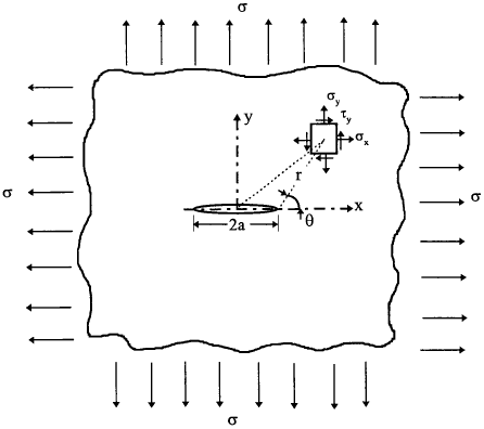
Note the origin of the coordinate is at the center of the crack. By transforming the origin to the right-hand crack tip, i.e., z = a + re−iθ, all the stress components can be derived. In the limit of small enough values of r/a, equation (2.24) can be expressed as
From differentiation of equation (2.24),
hence
For the configuration shown in Fig.2.10, the stresses can be expressed in a simple form, noting equation (1.14),
and displacement
where the K terms are the stress-intensity factors which embody the loading and geometry conditions. A complete list of the stress and displacement fields for three fracture modes is given in Table 2.1. The corresponding formulae for polar coordinates are given in Table 2.2.
The relative displacement between crack faces at position x is given by
for plane stress condition. Clearly the maximum crack opening occurs at the centre of the crack, equal to \( {2K \over E} \sqrt{a \over \pi} \). The stress distribution ahead of the crack tip, not necessarily near crack tip, is
Example 2.4 Estimate the relative size of the singularity dominated zone ahead of a through crack in an infinite plate subjected to remote uniaxial tension.
Solution Equations (2.27) and (2.28) can be rewritten as
$$ \sigma_{yy} = {K \over \sqrt{2 \pi r}} {(1 + r/a) \sqrt{2r / a} \over \sqrt{2r / a + (r/a)^2}} $$and
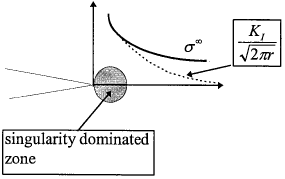
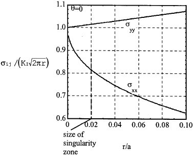
$$ \sigma_{xx} = {K \over \sqrt{2 \pi r}} \left( {(1 + r/a) \sqrt{2r / a} \over \sqrt{2r / a + (r/a)^2}} - \sqrt{2r / a} \right) $$Clearly the actual stress normal to the crack plane a σyy is higher than that given by equation (2.25a). Hence the singular solution is valid only near the crack tip; we define this as the singularity dominated zone, as shown in Fig.2.11. The size of this zone can be estimated by considering the ratio of the actual stress on the crack plane to the singularity limit. This is depicted in Fig.2.12. Note that the stress in the y direction is close to the singularity limit for relatively large distances from the crack tip, but the x stress diverges considerably from the near-tip limit. Let us arbitrarily define the singularity zone as the region within which the deviation is less than 20% for the x stress; this represents a value of r/a = 0.02. In other words, the term "singularity zone" is approximately one-fiftieth of the half crack size.
| Mode I | Mode II | Mode III | |
|---|---|---|---|
| σxx |
$$ {K_I \over \sqrt{2 \pi r}} \cos{\theta \over 2} \left[ 1 - \sin{\theta \over 2} \sin{3 \theta \over 2} \right] $$
|
$$ -{K_{II} \over \sqrt{2 \pi r}} \sin{\theta \over 2} \left[ 2 - \cos{\theta \over 2} \cos{3 \theta \over 2} \right] $$
|
0 |
| σyy |
$$ {K_I \over \sqrt{2 \pi r}} \cos{\theta \over 2} \left[ 1 + \sin{\theta \over 2} \sin{3 \theta \over 2} \right] $$
|
$$ {K_{II} \over \sqrt{2 \pi r}} \sin{\theta \over 2} \cos{\theta \over 2} \cos{3 \theta \over 2} $$
|
0 |
| τxy |
$$ {K_I \over \sqrt{2 \pi r}} \cos{\theta \over 2} \sin{\theta \over 2} \cos{3 \theta \over 2} $$
|
$$ {K_{II} \over \sqrt{2 \pi r}} \cos{\theta \over 2} \left[ 1 - \sin{\theta \over 2} \sin{3 \theta \over 2} \right] $$
|
0 |
| σzz |
$$
\left\{ \begin{array}{ll}
0 & \text{plane stress} \\
\nu (\sigma_{xx} + \sigma_{yy}) & \text{plane strain}
\end{array} \right.
$$
|
$$
\left\{ \begin{array}{ll}
0 & \text{plane stress} \\
\nu (\sigma_{xx} + \sigma_{yy}) & \text{plane strain}
\end{array} \right.
$$
|
0 |
| τxz | 0 | 0 |
$$ -{K_{III} \over \sqrt{2 \pi r}} \sin{\theta \over 2} $$
|
| τyz | 0 | 0 |
$$ {K_{III} \over \sqrt{2 \pi r}} \cos{\theta \over 2} $$
|
| ux |
$$ {K_I \over 2 \mu} \sqrt{r \over 2 \pi} \cos{\theta \over 2} \left[ \kappa - 1 + 2 \sin^2{\theta \over 2} \right] $$
|
$$ {K_{II} \over 2 \mu} \sqrt{r \over 2 \pi} \sin{\theta \over 2} \left[ \kappa + 1 + 2 \cos^2{\theta \over 2} \right] $$
|
0 |
| uy |
$$ {K_I \over 2 \mu} \sqrt{r \over 2 \pi} \sin{\theta \over 2} \left[ \kappa + 1 - 2 \cos^2{\theta \over 2} \right] $$
|
$$ {K_{II} \over 2 \mu} \sqrt{r \over 2 \pi} \cos{\theta \over 2} \left[ \kappa - 1 - 2 \sin^2{\theta \over 2} \right] $$
|
0 |
| uz |
$$
\left\{ \begin{array}{ll}
-{\nu z \over E} (\sigma_{xx} + \sigma_{yy}) & \text{plane stress} \\
0 & \text{plane strain}
\end{array} \right.
$$
|
$$
\left\{ \begin{array}{ll}
-{\nu z \over E} (\sigma_{xx} + \sigma_{yy}) & \text{plane stress} \\
0 & \text{plane strain}
\end{array} \right.
$$
|
$$ {K_{III} \over \mu} \sqrt{r \over 2 \pi} \sin{\theta \over 2} $$
|
| μ is the shear modulus, κ = 3 − 4ν for plane strain and κ = (3 − ν)/(1 + ν) for plane stress | |||
It is easy to show that the principal stresses for mode I are
| Mode I | Mode II | Mode III | |
|---|---|---|---|
| σrr |
$$ {K_I \over \sqrt{2 \pi r}} \cos{\theta \over 2} \left[ 1 + \sin^2{\theta \over 2} \right] $$
|
$$ {K_{II} \over \sqrt{2 \pi r}} \sin{\theta \over 2} \left[ 1 - 3 \sin^2{\theta \over 2} \right] $$
|
0 |
| σθθ |
$$ {K_I \over \sqrt{2 \pi r}} \cos^3{\theta \over 2} $$
|
$$ -{3 K_{II} \over \sqrt{2 \pi r}} \sin{\theta \over 2} \cos^2{\theta \over 2} $$
|
0 |
| τrθ |
$$ {K_I \over \sqrt{2 \pi r}} \sin{\theta \over 2} \cos^2{\theta \over 2} $$
|
$$ {K_{II} \over \sqrt{2 \pi r}} \cos{\theta \over 2} \left[ 1 - 3 \sin^2{\theta \over 2} \right] $$
|
0 |
| τxz | 0 | 0 |
$$ {K_{III} \over \sqrt{2 \pi r}} \sin{\theta \over 2} $$
|
| τyz | 0 | 0 |
$$ {K_{III} \over \sqrt{2 \pi r}} \cos{\theta \over 2} $$
|
In general the stress intensity factor depends on the applied stress, crack size, and the geometry,
where Y is called the geometry factor, signifying the geometry of a crack system in relation to the applied load. Normally this geometry factor can be looked up in technical reference books. For a centre crack in an infinite plate, Y = 1.0. The geometry of the cracked body imposes an effect on the new crack tip stress field, thus modifying the value of the stress intensity factor. In general, if the edge crack is situated in a strip of finite width, w, then the correction factor becomes a function of (a/w)
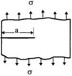
The simplest geometry factor is that for an edge crack of length, a, at the edge of a semi-infinite half space: the increased ability of the crack to open causes the stress intensity factor to increase by some 12%,
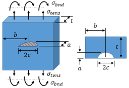
The determination of this geometry term is a problem of stress analysis. Any realistic geometry requires recourse to numerical methods, as very few closed form solutions exist. The most popular and efficient method is finite element analysis. Other techniques include experimental and semi-theoretical; more will be said about this later. Table 2.3 lists stress intensity factors and the geometry factors for a number of practical configurations. A more comprehensive list could be found in a two-volume handbook (Murakami, 1987).
| Geometry | Stress Intensity Factor | ||||||||||||||||||||||||
|---|---|---|---|---|---|---|---|---|---|---|---|---|---|---|---|---|---|---|---|---|---|---|---|---|---|
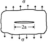
1. Crack in an infinite body
|
$$ K_I = \sigma \sqrt{\pi a} $$ | ||||||||||||||||||||||||
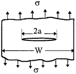
2. Centre crack in a strip of finite width
|
$$ K_I = \sqrt{ \sec{\pi a \over W} } ~\sigma \sqrt{\pi a} $$ | ||||||||||||||||||||||||
3. Edge crack in a semi-infinite body
|
$$ K_I = 1.12 ~\sigma \sqrt{\pi a} $$ | ||||||||||||||||||||||||
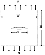
4. Centre crack in a finite width strip
|
$$ K_I = f\left({a \over W}\right) \sigma \sqrt{\pi a} $$
|
||||||||||||||||||||||||
5. Edge crack in a beam of width B subjected to bending

|
$$ K_I = f\left({a \over W}\right) \sigma \sqrt{\pi a} ~~~\text{where}~~~ \sigma = {6 M \over B W^2} $$
|
||||||||||||||||||||||||
6. Thin-section (plane stress) double split beam

|
$$ K_I = 2 \sqrt{3} ~{P a \over c^{~3/2}} $$ | ||||||||||||||||||||||||
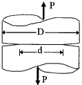
7. Circumferentially notched rod
|
$$ K_I = {0.932 P \sqrt{D} \over \sqrt{\pi d^2}} ~~~\text{for}~~~ 1.2 \le {D \over d} \lt 2.1 $$
|
||||||||||||||||||||||||
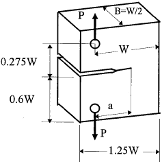
8. Compact tension specimen (CST)
|
$$ K_I = Y {P \sqrt{\pi} \over B \sqrt{W}} $$
$$
\begin{eqnarray}
Y &=& 16.7 \left({a \over W}\right)^{1/2} - 104.7 \left({a \over W}\right)^{3/2} \nonumber \\
&+& 369.9 \left({a \over W}\right)^{5/2} - 573.8 \left({a \over W}\right)^{7/2} \nonumber \\
&+& 360.5 \left({a \over W}\right)^{9/2}
\end{eqnarray}
$$
|
||||||||||||||||||||||||
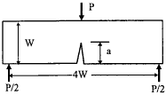
9. Single-edge notch bend (SENB), thickness B
|
$$ B = W / 2 $$
$$ K_I = Y {4 P \sqrt{\pi} \over B \sqrt{W}} $$
$$
\begin{eqnarray}
Y &=& 1.63 \left({a \over W}\right)^{1/2} - 2.6 \left({a \over W}\right)^{3/2} + 12.3 \left({a \over W}\right)^{5/2} \nonumber \\
&-& 21.3 \left({a \over W}\right)^{7/2} + 21.9 \left({a \over W}\right)^{9/2}
\end{eqnarray}
$$
|
||||||||||||||||||||||||
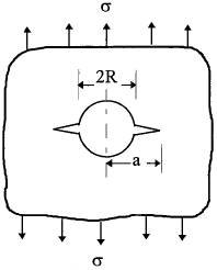
10. Crack emanating from a hole in an infinite body
|
$$ K_I = f\left({a \over R}\right) \sigma \sqrt{\pi a} $$
|
||||||||||||||||||||||||
A few points of interest arise from these solutions. Firstly, the stress intensity factor defines the amplitude of the crack tip singularity, and consequently the intensity of the local stress field. Local stresses near the crack tip are proportional to K, which uniquely defines the crack tip conditions. This single-parameter description of crack tip conditions is probably the most important concept of fracture mechanics. Secondly, it should be pointed that these solutions are valid only in the vicinity of the crack tip; higher order terms need to be taken into account when far field information is required.
Looking for Fracture Calculators?
Here are a few to choose from:
2.5 Superposition Method
Since the stresses and displacements are linearly proportional to the stress intensity factor, it follows that the superposition principle also applies to crack problems. This provides a very important tool for applying fracture mechanics to practical problems with the aid of handbooks. The underlying principle is that stresses induced by various loads can be added together. It should be pointed that the superposition method applies only to cases where a structure is subjected to various loads but of the same mode. For example, the crack tip stresses for a cracked component under combined tension and bending are,
Because the angular function fij(θ) is the same for the same fracture mode, the above equation can be rewritten as
where
In general, the stress intensity factor for a combination of load systems A, B, C can be obtained simply by superposition
and similarly for modes II and III.
Example 2.5 Determine the stress intensity factor for a edge cracked plate subjected to a combined tension and bending.

Solution
From Table 2.3, the stress intensity factor caused by the bending (case 5) is
$$ K^{(M)} = f_M \left({a \over W}\right) {6 M \over B W^2} \sqrt{\pi a} $$The stress intensity factor for the tension load (case 4) is
$$ K^{(P)} = f_P \left({a \over W}\right) {P \over B W} \sqrt{\pi a} $$Thus the total stress intensity factor is
$$ K = \sqrt{\pi a} \left[ {P \over B W} f_P \left({a \over W}\right) + {6 M \over B W^2} f_M \left({a \over W}\right) \right] $$For a ratio a/W = 0.2, we have
$$ K = \sqrt{\pi a} \left( 1.21 {P \over B W} + 1.055 {6 M \over B W^2} \right) $$Example 2.6 Consider a symmetric case of two very small cracks at a circular hole (See Fig.2.14(a)) along the x-axis in a wide plate subjected to uniaxial tension σ along the y-axis. Determine the stress intensity factor.
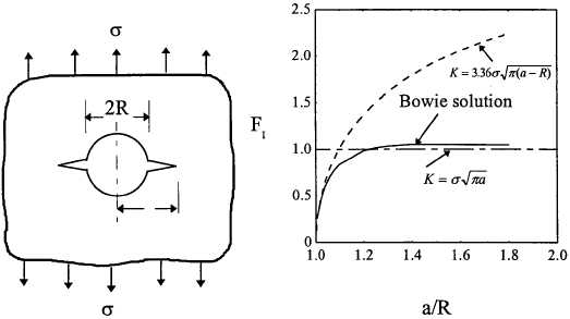
(a) Two symmetrical cracks emanating from a circular hole and (b) the stress intensity factor.
Solution Due to the stress concentration near the circular hole (Kt = 3) an element at the rim of the hole is subjected to a tensile stress 3σ along the y-axis. By the principal of superposition and for a small crack length, we have
which is shown in Fig.2.14 together with the numerical solution obtained by Bowie (1956).
Clearly for very short cracks the above approximation is very close to the numerical solution. For long cracks (crack length a ≫ R), we may assume as an engineering approach that the combination behaves as if the hole were part of the crack, hence \( K = \sigma \sqrt{\pi a} \). As shown in Fig.2.14, these two asymptotic solutions provide two bounds to the actual solution.
Looking for Fracture Calculators?
Here are a few to choose from:
2.6 Relationship Between G and K
We can now return to the Griffith's energy concept, with special reference to its relation to the stress intensity factor. Proceeding as before, we may identify the mechanical energy release during the crack extension with the work done by hypothetically imposed surface tractions. As illustrated in Fig. 2.15, forces are applied to the crack edge, sufficient to close the crack over an infinitesimal distance. The work done by this force is obviously equal to the amount of energy that needs to be consumed in order to make the crack grow by this distance.

Thus the strain-energy release for a crack growth of δ may be expressed as
where the factor 2 arises because the crack has two opposing crack surfaces, and the factor ½ is because of the assumed proportionality between tractions and the corresponding displacement. The thickness of the plate is denoted as B. After substituting the expressions for σy and uy (see Table 3.1), the integration of equation (2.34) leads to
for plane stress. Similarly, for plane strain condition (see Chapter 1)
It can also be shown for mode II and mode III,
| $$ G_{II} = (1 - \nu^2) {K_{II}^2 \over E} $$ | and | $$ G_{III} = (1 + \nu) {K_{III}^2 \over E} $$ |
for plane strain condition.
The total energy release rate in combined mode cracking can be obtained by summing up the energies for different modes:
However, it is important to note that the derivation of both the stress intensity factor and the strain energy release rate is independent of the actual fracture process hence critical condition of materials. In other words, these only represent the "driving" force for crack growth and bear no relations to the materials' "resistance". This will be discussed in the next chapter.
Example 2.7 For double cantilever beam (DCB) shown in Example 2.2 determine the stress intensity factor KI using elementary beam theory for applied load P or applied displacement u.
Solution
From the previous analysis, the energy release rate for the cracked system is
$$ G = {12 P^2 a^2 \over E B^2 h^3} $$the stress intensity factor is, according to equation (2.40)
$$ K = \sqrt{EG \over (1 - \nu^2)} = {2 \sqrt{3} \over \sqrt{1 - \nu^2}} {Pa \over B h^{3/2}} $$for plane strain condition. Obviously the "driving" force increases linearly with crack length for a constant applied load. The stress intensity factor can also be expressed in terms of the displacement, u,
$$ K = {\sqrt{3} h^{3/2} Eu \over 4 \sqrt{1 - \nu^2} a^2} $$It should be observed that, under displacement control, the stress intensity factor decreases as the crack extends. Therefore the system is a stable one, in the sense that the crack would stop growing after a certain crack advance unless the displacement is further increased.
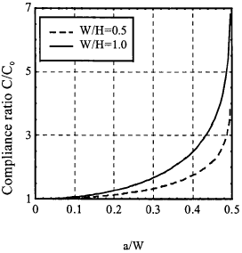
Example 2.8 Determine compliance of a centre cracked specimen of width W and crack length 2a. The thickness and height of the specimen are B and H, respectively. The stress intensity factor is given in Table 2.3.
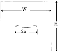
Solution From Table 2.3 the stress intensity factor is
$$ K = \sqrt{\sec{\pi a \over W}} ~\sigma \sqrt{\pi a} $$Since
$$ G = {P^2 \over 2} {\partial C \over \partial A} = {P^2 \over 4B} {dC \over da} $$for centre cracked plate and
$$ G = {K^2 \over E} $$we have
$$ \left({dC \over da}\right)_P = {4B \over EP^2} \sigma^2 \pi a \sec{\pi a \over W} = {4 \over EBW^2} \pi a ~\sec \left({\pi a \over W}\right) $$hence the compliance is
$$ C = \int_0^a {4 \over EBW} {\pi a \over W} \sec \left({\pi a \over W}\right) da + C_0 $$where constant C0 represents the compliance of the specimen without crack, that is
$$ C_0 = {\Delta \over P} = {\varepsilon H \over \sigma B W} = {H \over EBW} $$To facilitate the integration, we adopt the following approximation
$$ {\pi a \over W} \sec \left({\pi a \over W}\right) = \tan \left({\pi a \over W}\right) { {\pi \over W} a \over \sin \left({\pi a \over W}\right) } \approx \tan \left({\pi a \over W}\right) $$For comparison, two ratio between the two functions are shown in Fig.2.17. It is seen that the error is less than 10 percent up to a ratio 2a/W = 0.5.
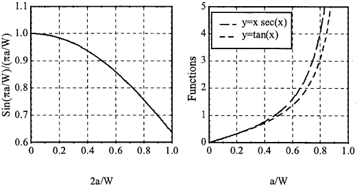
Now the compliance can be expressed as
This is graphically shown below. Clearly the compliance of the specimen increases rapidly as the crack length increases.
These two examples demonstrate that the relationship between the energy release rate and stress intensity factor is not only useful in determining the stress intensity factor for a cracked component from compliance measurement or calculation, but also useful in assessing the compliance of a cracked component.
