Energy Concepts for Crack Growth
This page provides the sections on energy balance and energy release rate during crack growth from Wang, C. H. "Introduction to Fracture Mechanics," DSTO Aeronautical and Maritime Research Laboratory, DSTO-GD-0103, 1996.
Other related chapters from "Introduction to Fracture Mechanics" can be seen to the right.
2.1 Energy Balance During Crack Growth
The obvious difference between a cracked body and an uncracked body is the additional surface associated with a crack. It is a well known fact that creating new (crack) surfaces consumes energies, because surfaces carry higher energy than the body. It then follows that whether or not a stressed cracked body remains stable or becomes unstable is dependent on whether the cracked body contains sufficient energy to afford to creating additional surface while still maintains equilibrium. This is the basic concept that Griffith proposed in the 1920's to formulate a linear elastic theory of crack propagation. To illustrate this point, let us consider an elastic body Γ containing an internal crack of length 2a, which is subjected to loads applied at the outer boundary S; see Fig.2.1.
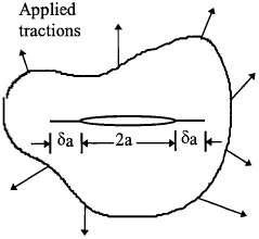
According to the law of conservation of energy the work performed per unit time by the applied loads (\( \dot{W} \)) must be equal to the rates of change of the internal elastic energy (\( \dot{U}_E \)), plastic energy (\( \dot{U}_P \)), kinetic energy (\( \dot{K} \)) of the body, and the energy per unit time (\( \dot{\Gamma} \)) spent in increasing the crack area. In other words,
where a dot over the letter refers to differentiation with respect to time.
If the crack grows slowly the kinematic energy K (or \(\dot{K}\) = 0) is negligible and can be omitted from the energy balance equation. Since all changes with respect to time are caused by changes in crack size, we have
where A represents the crack area, and is equal to 2aB for the system shown in Fig.2.1. Here B is the thickness of the plate containing the crack and \( \dot{A} \) denotes the crack surface area growth rate per unit time. Note that the total crack surface area is twice the area of one crack surface. Therefore equation (2.1) can be rewritten as
where
is the potential energy of the system. Equation (2.3) indicates that the reduction of potential energy is equal to the energy dissipated in plastic work and surface creation.
Looking for Fracture Calculators?
Here are a few to choose from:
2.2 Griffith Theory
For an ideally brittle material, the energy dissipated in plastic deformation is negligible and can be ignored, i.e. UP = 0. Since the energy spent in increasing the crack area is independent of the crack size, equation (2.3) can be rewritten as
where γ represents the energy required to form unit new material surface area. The factor 2 in the above equation refers to the two new material surfaces formed during crack growth. Simply, the above equilibrium equation means that sufficient potential energy must be available in the system to overcome the surface energy of the material. In general, for an elastic body containing a crack, we can define a crack-extension force, G,
per unit width of crack front. Note that A = a · B when there is only one crack tip (e.g. edge cracked component) and A = 2a · B for centre cracked system. It is important to note the distinction between crack area and surface area. Since a crack includes two matching surfaces, the crack surface area is twice that of the projected crack area, and is equal to 2aB in the present case.
We can also define the total energy of the system, which contains three parts: (1) the amount of work done by the applied loads, (2) the elastic energy, and (3) the energy required to form the crack surface. The total energy is
According to linear elasticity theory, a body under constant applied loads obeys
which is sometimes called Clapeyron's theorem of linear elastostatics; a simple proof of which will be shown later. In this case equation (2.6) can be expressed as
The total energy of the system is
Griffith used the stress solutions by Inglis (1939) to show that the increase in strain energy due to the elliptic cavity (zero radius) in an infinite plane is given by
where B is the plate thickness, and
where γ is the free surface energy per unit area, which is clearly a material constant. Thus, the total system energy becomes, for the case of a thin plate,
A schematic drawing of the above equation is shown in Fig 2.2, which exhibits a maximum at the following crack length,
Clearly the critical crack length below which the crack would remain stable decreases quickly with stress level. Alternatively, the critical stress level that a cracked body can sustain is
for constant load under plane stress condition.
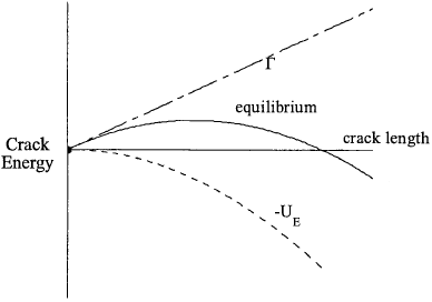
There are two important implications of equation (2.15). Firstly, the critical stress level for a given crack length varies with materials, viz some materials (with high surface energy) are tougher than others. Secondly, the critical stress level decreases with crack length, i.e. the larger the crack, the easier it may become unstable.
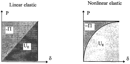
The physical meaning of the energy release rate G is that it characterises the amount of energy that would be released if the crack advances a unit length. When this value is greater than the surface energy of the material, then crack growth would occur, otherwise, no crack propagation would be possible. It should be pointed out that equation (2.9) is correct only when the cracked body behaves linearly; if the object is nonlinear elastic or considerable plasticity occurs, equation (2.8) is no longer valid and hence the original equation (2.6) should be used instead. A graphical illustration is shown in Fig. 2.3. For linear elastic problem, the potential energy Π = UE - W is equal to the area of the triangle (but opposite in sign), incidentally it is also equal to the strain energy in this instance. If the elastic body is nonlinear, like rubber, Π is equal to the upper hatched area, while UE is actually equal to the area below the load-deflection curve.
Looking for Fracture Calculators?
Here are a few to choose from:
2.3 Energy Release Rate G and Compliance
The energy release rate G defined in equation (2.9) provides a powerful tool for studying fracture problems of cracked bodies from a global view. The energy release rate is sometimes referred to as the rate of strain energy flux flowing toward a crack tip as the crack extends.
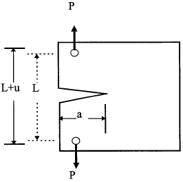
Let us consider the load displacement curve for a cracked specimen made of linear elastic media as shown in Fig.2.4. When the crack has length a, the specimen is less compliant than when the crack has length a + δa. The compliance C of the specimen is the displacement per unit load, i.e the reciprocal of stiffness. In general we may write
which is a geometry constant, dependent on crack length and dimensions of the body. Here the displacement u refers to the relative displacement measured between the loading points; see Fig.2.4. A cracked body may be subjected to loads or displacement, or a combination of both. In the following we will consider two extreme cases: constant load (Fig.2.5a) and constant displacement or "fixed grip" condition (Fig.2.5b), separately.

2.3.1 Constant Load Conditions
As discussed previously, the potential energy in the specimen is the area above the load-displacement curve (the area below the load versus displacement curve is the strain energy stored in the specimen while the area of the rectangle is the work done by external force). The potential energy change δΠ is the difference between the external work done and the stored but recoverable elastic strain energy. The energy stored in the specimen for a crack of length a + δa is greater than in the situation when the crack was length a, the increase being
However, to attain this stored energy the load has moved a distance u2 − u1 and so the work done by the external applied load is
Clearly the elastic energy stored in the system which could be released back to the environment after crack extension is less than the work done by the applied loads. The amount of the energy that appears to have "vanished" is equal to
which is the hatched area in Fig.2.5(a), equal to the energy spent in increasing crack surfaces. In this case, the energy required for crack extension is not supplied by the existing strain energy stored in the system, but the work performed by the external loads; the elastic energy of the solid is actually increased. Thus the term "strain energy release rate" in this case is physically inappropriate. A better name should be "potential energy release rate".
2.3.2 Constant Displacement Condition
Similarly, under fixed grip condition, an increase in crack length causes a decrease in stored elastic strain energy given by
which is the hatched area in Fig.2.5(b). Since no external work is done, the above energy is that spent in increasing crack surfaces.
2.3.3 Determination Of Energy Release Rate From Compliance
To summarise the above results for constant load and constant displacement,
- the constant load condition requires a potential energy release rate of ½Pδu.
- the fixed-grip condition requires a potential energy release of ½uδP.
In mathematical terms as δA tends to zero we can say that the compliance of C is the same for both cases, which is the same as stating that the difference between the two shaded areas of Fig.2.5 tends to zero. In other words, δu = CδP, and the release of energy for crack extension in both cases is given by
Therefore the strain (or potential) energy release rate (with respect to crack length) for small crack extension δA can, therefore, be found experimentally in a plate of uniform thickness B as
Thus by taking measurements of the compliance of a specimen with different crack lengths, it is possible to determine δC/δa for a given crack length and so determine G. Note A = a · B when there is only one crack tip (e.g. edge cracked component) and A = 2a · B for centre cracked system. However, it is important to note that the strain energy release rate is identical for constant load and constant displacement conditions. As indicated by equation (2.22), the strain energy release for a given applied load is proportional to the differentiative of the compliance with respect to crack length, independent of loading condition.
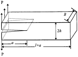
Example 2.1 For a double cantilever beam (DCB) with a ≫ 2h and l ≫ 2h, as shown in Fig.2.6, determine the strain energy release rate G.
Solution
The two arms of the DCB may be considered to a first approximation as cantilevers.
Method 1: The displacement at the loading point is
| $$ u = {P a^3 \over 3 EI} $$ | where | $$ I = {B h^3 \over 12} $$ |
hence the relative displacement of the two points of load application is
$$ v = 2u = {8 P a^3 \over E B h^3} $$thus the compliance of the specimen is
$$ C = {v \over P} = {8 a^3 \over E B h^3} $$It follows that the energy release rate G is
$$ G = {P^2 \over 2B} {\partial C \over \partial a} = {12 P^2 a^2 \over E B^2 h^3} $$Method 2: The strain energy stored in the cantilever beam specimen can be easily obtained by integration,
$$ U_E = 2 \int_0^a {M^2(x) \over 2EI} dx $$according to equation (2.9) the energy release rate is
Example 2.2 Determine the energy release rate for a end notched flexure (ENF) component, shown in Fig.2.7, which is adhesively bonded.
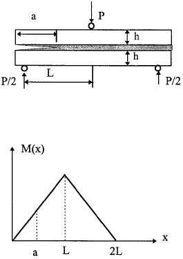
Solution Similar to the previous example, the strain energy stored in the component is
where E is the Young's modulus of the plate and
| $$ M_1 (x) = {Px \over 2} $$ | $$ I_1 = {B h^3 \over 12} $$ |
| $$ M_2 (x) = PL - {P x \over 2} $$ | $$ I_2 = {B (2h)^3 \over 12} = {8 B h^3 \over 12} $$ |
so
hence the energy release rate is
Example 2.3 Determine the energy release rate for a cracked lap shear (CLS) specimen (see Fig.2.8).
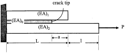
Solution Assuming the bending deflection of the overhang region does not contribute to the strain energy, the strain energy stored in the system is
$$ U_E = \int_0^{L-a} {P^2 \over 2 (EA)_0} dx + \int_{L-a}^{L+l} {P^2 \over 2 (EA)_2} dx $$thus the energy release rate is
It is interesting to note that, unlike the previous example, the energy release rate for a cracked lap shear specimen is independent of crack length. This feature offers a convenient method in determining the critical energy release rate, as the precise location of the crack tip is not important.
It should be pointed that the above method applies only when the entire system, including adhesive, is elastic. When the adhesive yields, a rather more complicated analysis using elasto-plastic fracture mechanics is required. Furthermore, the local bending effect due to load eccentricity is ignored in the present analysis. In reality, when the overhang length, l, is sufficiently long, geometrically nonlinear deformation would occur, which will induce a local peel stress at the crack tip, hence a mode I fracture component.
